2020 Hyundai Santa Fe auto seat
[x] Cancel search: auto seatPage 296 of 557

5-22
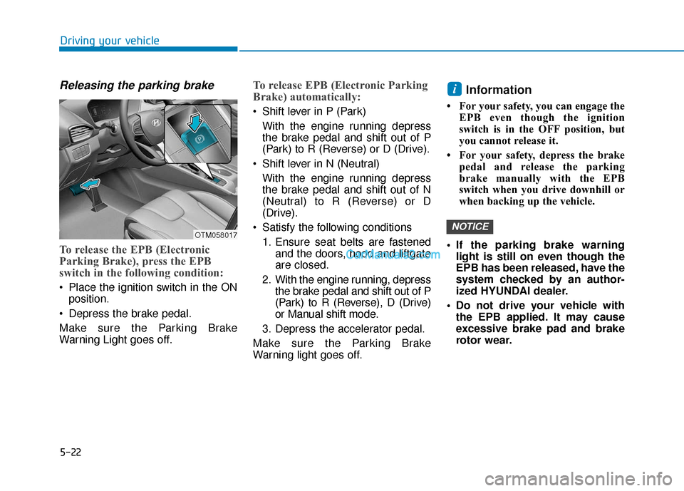
Releasing the parking brake
To release the EPB (Electronic
Parking Brake), press the EPB
switch in the following condition:
Place the ignition switch in the ONposition.
Depress the brake pedal.
Make sure the Parking Brake
Warning Light goes off.
To release EPB (Electronic Parking
Brake) automatically:
Shift lever in P (Park) With the engine running depress
the brake pedal and shift out of P
(Park) to R (Reverse) or D (Drive).
Shift lever in N (Neutral) With the engine running depress
the brake pedal and shift out of N
(Neutral) to R (Reverse) or D
(Drive).
Satisfy the following conditions 1. Ensure seat belts are fastened and the doors, hood and liftgate
are closed.
2. With the engine running, depress the brake pedal and shift out of P
(Park) to R (Reverse), D (Drive)
or Manual shift mode.
3. Depress the accelerator pedal.
Make sure the Parking Brake
Warning light goes off.
Information
• For your safety, you can engage the EPB even though the ignition
switch is in the OFF position, but
you cannot release it.
• For your safety, depress the brake pedal and release the parking
brake manually with the EPB
switch when you drive downhill or
when backing up the vehicle.
If the parking brake warning light is still on even though the
EPB has been released, have the
system checked by an author-
ized HYUNDAI dealer.
Do not drive your vehicle with the EPB applied. It may cause
excessive brake pad and brake
rotor wear.
NOTICE
i
Driving your vehicle
OTM058017
Page 297 of 557

5-23
Driving your vehicle
EPB (Electronic Parking Brake)
may be automatically applied
when:
Requested by other systems
The driver turns the engine offwhile Auto Hold is operating.
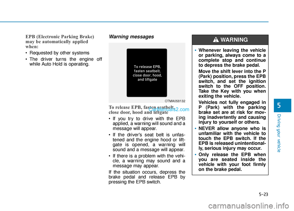
Warning messages
To release EPB, fasten seatbelt,
close door, hood and liftgate
If you try to drive with the EPBapplied, a warning will sound and a
message will appear.
If the driver's seat belt is unfas- tened and the engine hood or lift-
gate is opened, a warning will
sound and a message will appear.
If there is a problem with the vehi- cle, a warning may sound and a
message may appear.
If the situation occurs, depress the
brake pedal and release EPB by
pressing the EPB switch.
5
OTMA058132
Whenever leaving the vehicle
or parking, always come to a
complete stop and continue
to depress the brake pedal.
Move the shift lever into the P
(Park) position, press the EPB
switch, and set the ignition
switch to the OFF position.
Take the Key with you when
exiting the vehicle.
Vehicles not fully engaged in
P (Park) with the parking
brake set are at risk for mov-
ing inadvertently and causing
injury to yourself or others.
NEVER allow anyone who is
unfamiliar with the vehicle to
touch the EPB switch. If the
EPB is released unintentional-
ly, serious injury may occur.
Only release the EPB when
you are seated inside the
vehicle with your foot firmly
on the brake pedal.
WARNING
Page 320 of 557

5-46
The ISG system helps reduce fuel
consumption and exhaust gas emis-
sions by automatically shutting down
the engine, when the vehicle is at a
standstill (i.e. red stop light, stop
sign, and traffic jam).
The engine is automatically started
upon satisfying the starting condi-
tions.
The ISG system is always active,
when the engine is running.
Information
When the engine is automatically
started by the ISG system, some warn-
ing lights (i.e. ABS, ESC, ESC OFF,
EPS, and parking brake warning
light) may illuminate for a few sec-
onds due to the low battery voltage.
However, it does not indicate a mal-
function with the ISG system.
To Activate the ISG System
Prerequisite for activation
The ISG system operates in the fol-
lowing situations.
The driver's seatbelt is fastened
The driver's door and hood areclosed
The brake vacuum pressure is adequate
The battery sensor is activated and the battery is sufficiently
charged
Outside temperature is not too low or too high
The vehicle is driven over a con- stant speed and stops
The climate control system satis- fies the conditions
The vehicle is sufficiently warmed up
The incline is gradual
The steering wheel is turned less than 180 degrees and then the
vehicle stops
Information
The ISG system is
not activated, when
the prerequisites to
activate the ISG sys-
tem are unsatisfied.
In this case, the ISG
OFF button indicator illuminates,
and the auto stop indicator ( )
illuminates in yellow on the instru-
ment cluster.
• When the above indicator remains illuminated on the instrument clus-
ter, we recommend that you have
the ISG system checked by an
authorized HYUNDAI dealer.
i
i
I
IS
S G
G
(
( I
ID
D L
LE
E
S
S T
T O
O P
P
A
A N
N D
D
G
G O
O )
)
S
S Y
Y S
ST
T E
EM
M
(
( I
IF
F
E
E Q
Q U
UI
IP
P P
PE
ED
D )
)
Driving your vehicle
•
Page 322 of 557

5-48
Auto start
To restart the engine in the auto
stop mode
Release the brake pedal.
- When Auto Hold is activated, if yourelease the brake pedal, the
engine will be in the auto stop
state. However, if you depress the
accelerator pedal, the engine will
start again.
The auto stop indicator ( ) goes
OFF on the instrument cluster, when
the engine is restarted.
The engine is automatically restart-
ed in the following situations.
The brake vacuum pressure is low
The engine has stopped for about 5 minutes
The air conditioning is ON with the fan speed set to the highest posi-
tion
The front defroster is ON
The battery is weak
The cooling and heating perform- ance of the climate control system
is unsatisfactory
The vehicle is shifted to P (Park) when Auto Hold is activated
The door is opened or the seatbelt is unfastened when Auto Hold is
activated
The EPB switch is pressed when Auto Hold is activated
The auto stop indicator ( ) blinks
in green for 5 seconds on the instru-
ment cluster.
The auto start is temporarily deac-
tivated in the following situations.
When the shift lever is shifted from N
(Neutral) to R (Reverse), D (Drive) or
Manual shift mode without the brake
pedal depressed. A message "Press
brake pedal for Auto Start" will
appear on the LCD display. To acti-
vate auto start, depress the brake
pedal.
Driving your vehicle
OIK057086N
Page 332 of 557

5-58
Driving your vehicle
- If you select "Warning Only", the FCA system activates and pro-
duces only warning alarms in
accordance with the collision risk
levels. You should control the brake
directly because the FCA system
do not control the brake.
Brake operation
In an urgent situation, the braking system enters into the ready status
for prompt reaction against the dri-
ver’s depressing the brake pedal.
The FCA provides additional brak- ing power for optimum braking per-
formance, when the driver
depresses the brake pedal.
The braking control is automatical- ly deactivated, when the driver
sharply depresses the accelerator
pedal, or when the driver abruptly
operates the steering wheel.
The FCA braking control is auto- matically canceled, when risk fac-
tors disappear.
The driver should always use
extreme caution while operat-
ing the vehicle, whether or not
there is a warning message or
alarm from the FCA system.
If any other warning sound such
as seat belt warning chime is
already generated, the Forward
Collision-Avoidance Assist (FCA)
system warning may not sound.
CAUTION
The FCA system logic operates
within certain parameters, such
as the distance from the vehicle
or pedestrian ahead, the speed
of the vehicle ahead, and the
driver's vehicle speed. Certain
conditions such as inclement
weather and road conditions
may affect the operation of the
FCA system.
WARNING
The FCA braking control cannot
completely stop the vehicle nor
avoid all collisions. The driver
should hold the responsibility
to safely drive and control the
vehicle.
WARNING
Never deliberately drive danger-
ously to activate the system.
WARNING
Page 449 of 557

Check headlamp alignment.
Check muffler, exhaust pipes,shields and clamps.
Check seat belts for wear and function.
At least once a year:
Clean body and door drain holes.
Lubricate door hinges and hoodhinges.
Lubricate door and hood locks and latches.
Lubricate door rubber weather strips.
Lubricate door checker.
Check the air conditioning system.
Inspect and lubricate automatic transmission linkage and controls.
Clean the battery and terminals.
Check the brake fluid level. Follow Normal Maintenance Schedule
if the vehicle is usually operated where
none of the following conditions apply.
If any of the following conditions apply,
you must follow the Maintenance
Under Severe Usage Conditions.
Repeatedly driving short dis-
tances of less than 5 miles (8 km)
in normal temperature or less than
10 miles (16 km) in freezing tem-
perature
Extensive engine idling or low speed driving for long distances
Driving on rough, dusty, muddy, unpaved, graveled or salt- spread
roads
Driving in areas using salt or other corrosive materials or in very cold
weather
Driving in heavy dust conditions
Driving in heavy traffic area Driving on uphill, downhill, or
mountain road
Towing a trailer, or using a camper, or roof rack
Driving as a patrol car, taxi, other commercial use or vehicle towing
Driving over 106 mph (170 km/h)
Frequently driving in stop-and-go conditions
For additional information or assis-
tance see your authorized HYUNDAI
dealer.
S S C
C H
H E
ED
D U
U L
LE
E D
D
M
M A
AI
IN
N T
TE
EN
N A
AN
N C
CE
E
S
S E
E R
R V
V I
IC
C E
E S
S
Maintenance
7
7-7
Page 489 of 557

Tire Terminology and
Definitions
Air Pressure
The amount of air inside the tire
pressing outward on the tire. Air
pressure is expressed in pounds per
square inch (psi) or kilopascal (kPa).
Accessory Weight
This means the combined weight of
optional accessories. Some exam-
ples of optional accessories are
automatic transmission, power
seats, and air conditioning.
Aspect Ratio
The relationship of a tire's height to
its width.
Belt
A rubber coated layer of cords that is
located between the plies and the
tread. Cords may be made from steel
or other reinforcing materials.
Bead
The tire bead contains steel wires
wrapped by steel cords that hold the
tire onto the rim.
Bias Ply Tire
A pneumatic tire in which the plies
are laid at alternate angles less than
90 degrees to the centerline of the
tread.
Cold Tire Pressure
The amount of air pressure in a tire,
measured in pounds per square inch
(psi) or kilopascals (kPa) before a tire
has built up heat from driving.
Curb Weight
This means the weight of a motor
vehicle with standard and optional
equipment including the maximum
capacity of fuel, oil and coolant, but
without passengers and cargo.
DOT Markings
A code molded into the sidewall of a
tire signifying that the tire is in com-
pliance with the U.S. Department of
Transportation motor vehicle safety
standards. The DOT code includes
the Tire Identification Number (TIN),
an alphanumeric designator which
can also identify the tire manufactur-
er, production plant, brand and date
of production.
GVWR
Gross Vehicle Weight Rating
GAWR FRT
Gross Axle Weight Rating for the
Front Axle.
GAWR RR
Gross Axle Weight Rating for the
Rear axle.
Intended Outboard Sidewall
The side of an asymmetrical tire, that
must always face outward when
mounted on a vehicle.
Maintenance
7
7-47
Page 490 of 557

Kilopascal (kPa)
The metric unit for air pressure.
Light truck(LT) tire
A tire designated by its manufacturer
as primarily intended for use on light-
weight trucks or multipurpose pas-
senger vehicles.
Load ratings
The maximum load that a tire is rated
to carry for a given inflation pressure.
Load Index
An assigned number ranging from 1
to 279 that corresponds to the load
carrying capacity of a tire.
Maximum Inflation Pressure
The maximum air pressure to which
a cold tire may be inflated. The max-
imum air pressure is molded onto the
sidewall.
Maximum Load Rating
The load rating for a tire at the maxi-
mum permissible inflation pressure
for that tire.
Maximum Loaded VehicleWeight
The sum of curb weight; accessory
weight; vehicle capacity weight; and
production options weight.
Normal Occupant Weight
The number of occupants a vehicle
is designed to seat multiplied by 150
pounds (68 kg).
Occupant Distribution
Designated seating positions.
Outward Facing Sidewall
An asymmetrical tire has a particular
side that faces outward when mount-
ed on a vehicle. The outward facing
sidewall bears white lettering or
bears manufacturer, brand, and/or
model name molding that is higher or
deeper than the same moldings on
the inner facing sidewall.
Passenger (P-Metric) tire
A tire used on passenger cars and
some light duty trucks and multipur-
pose vehicles.
Ply
A layer of rubber-coated parallel
cords.
Pneumatic tire
A mechanical device made of rubber,
chemicals, fabric and steel or other
materials, that, when mounted on an
automotive wheel provides the trac-
tion and contains the gas or fluid that
sustains the load.
Pneumatic options weight
The combined weight of installed
regular production options weighing
over 5 lb. (2.3 kg) in excess of the
standard items which they replace,
not previously considered in curb
weight or accessory weight, includ-
ing heavy duty breaks, ride levelers,
roof rack, heavy duty battery, and
special trim.
Maintenance
7-48