2020 HYUNDAI NEXO warning light
[x] Cancel search: warning lightPage 400 of 561
6-2
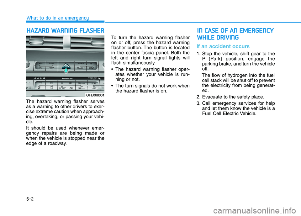
The hazard warning flasher serves
as a warning to other drivers to exer-
cise extreme caution when approach-
ing, overtaking, or passing your vehi-
cle.
It should be used whenever emer-
gency repairs are being made or
when the vehicle is stopped near the
edge of a roadway.To turn the hazard warning flasher
on or off, press the hazard warning
flasher button. The button is located
in the center fascia panel. Both the
left and right turn signal lights will
flash simultaneously.
• The hazard warning flasher oper-
ates whether your vehicle is run-
ning or not.
The turn signals do not work when
the hazard flasher is on.
If an accident occurs
1. Stop the vehicle, shift gear to the
P (Park) position, engage the
parking brake, and turn the vehicle
off.
The flow of hydrogen into the fuel
cell stack will be shut off to prevent
the electricity from being generat-
ed.
2. Evacuate to the safety place.
3. Call emergency services for help
and let them know the vehicle is a
Fuel Cell Electric Vehicle.
H HA
AZ
ZA
AR
RD
D
W
WA
AR
RN
NI
IN
NG
G
F
FL
LA
AS
SH
HE
ER
R
What to do in an emergency
OFE068001
I IN
N
C
CA
AS
SE
E
O
OF
F
A
AN
N
E
EM
ME
ER
RG
GE
EN
NC
CY
Y
W WH
HI
IL
LE
E
D
DR
RI
IV
VI
IN
NG
G
Page 411 of 561
6-13
What to do in an emergency
6
If any of the below happens, have
the system checked by an author-
ized HYUNDAI dealer.
1. The Low Tire Pressure TPMS
Malfunction Indicator does not
illuminate for 3 seconds when
the POWER button is placed to
the ON position or vehicle is ON
( indicator ON).
2. The TPMS Malfunction Indicator
remains illuminated after blink-
ing for approximately 1 minute.
3. The Low Tire Pressure LCD dis-
play remains illuminated
Low Tire Pressure
Telltale
Low Tire Pressure
LCD Display with
Position Indicator
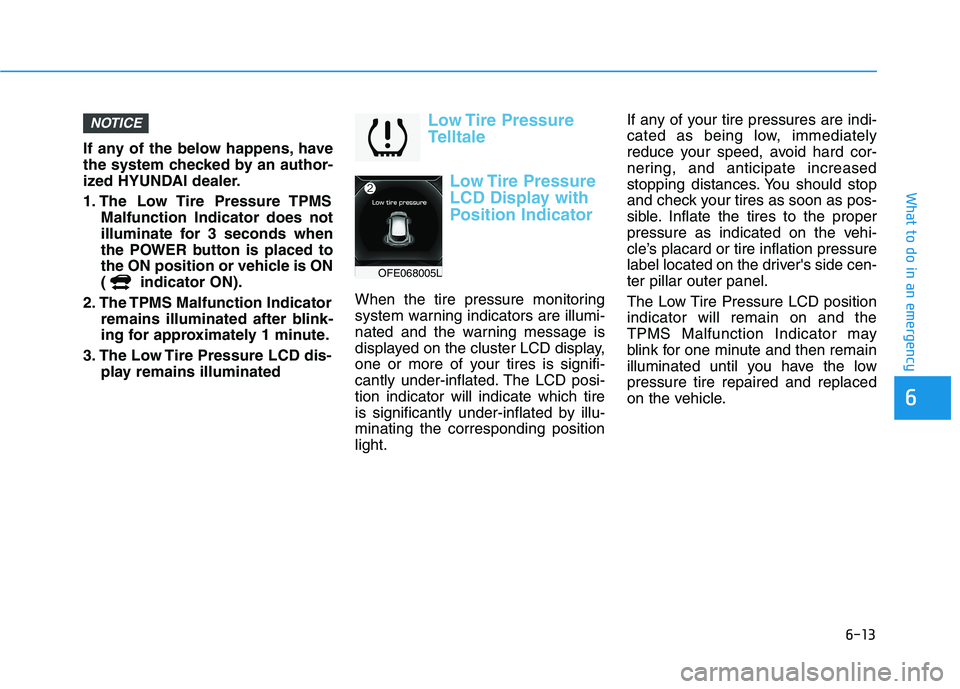
When the tire pressure monitoring
system warning indicators are illumi-
nated and the warning message is
displayed on the cluster LCD display,
one or more of your tires is signifi-
cantly under-inflated. The LCD posi-
tion indicator will indicate which tire
is significantly under-inflated by illu-
minating the corresponding position
light.If any of your tire pressures are indi-
cated as being low, immediately
reduce your speed, avoid hard cor-
nering, and anticipate increased
stopping distances. You should stop
and check your tires as soon as pos-
sible. Inflate the tires to the proper
pressure as indicated on the vehi-
cle’s placard or tire inflation pressure
label located on the driver's side cen-
ter pillar outer panel.
The Low Tire Pressure LCD position
indicator will remain on and the
TPMS Malfunction Indicator may
blink for one minute and then remain
illuminated until you have the low
pressure tire repaired and replaced
on the vehicle.
NOTICE
OFE068005L
Page 414 of 561
6-16
What to do in an emergency
You may not be able identify a tire
with low pressure by simply looking
at it. Always use a good quality tire
pressure gage to measure the tire's
inflation pressure. Please note that a
tire that is hot (from being driven) will
have a higher pressure measure-
ment than a tire that is cold.
A cold tire means the vehicle has
been sitting for 3 hours and driven for
less than 1 mile (1.6 km) in that 3
hour period.
Allow the tire to cool before measur-
ing the inflation pressure. Always be
sure the tire is cold before inflating to
the recommended pressure.
Information
This device complies with Part 15 of
the FCC rules.
Operation is subject to the following
three conditions:
1. This device may not cause harmful
interference.
2. This device must accept any inter-
ference received, including interfer-
ence that may cause undesired
operation.
3. Changes or modifications not
expressly approved by the party
responsible for compliance could
void the user's authority to operate
the equipment.
i
The TPMS cannot alert you to
severe and sudden tire dam-
age caused by external fac-
tors such as nails or road
debris.
If you feel any vehicle instabil-
ity, immediately take your foot
off the accelerator, apply the
brakes gradually with light
force, and slowly move to a
safe position off the road.
WARNING
Tampering with, modifying, or
disabling the Tire Pressure
Monitoring System (TPMS)
components may interfere with
the system's ability to warn the
driver of low tire pressure con-
ditions and/or TPMS malfunc-
tions. Tampering with, modify-
ing, or disabling the Tire
Pressure Monitoring System
(TPMS) components may void
the warranty for that portion of
the vehicle.
WARNING
Page 431 of 561
7-6
Maintenance
Owner maintenance schedule
When you stop for fuel:
• Check for both fuel cell stack andDevice cooling coolant level in
coolant reservoir.
Check the windshield washer fluid level.
Look for low or under-inflated tires.
While operating your vehicle:
Check for vibrations in the steering wheel. Notice if there is any
increased steering effort or loose-
ness in the steering wheel, or
change in its straight-ahead posi-
tion.
Notice if your vehicle constantly turns slightly or "pulls" to one side
when traveling on smooth, level
road.
When stopping, listen and check for unusual sounds, pulling to one
side, increased brake pedal travel
or "hard-to-push" brake pedal.
If any slipping or changes in the operation of your reduction gear
occurs, check the reduction gear
fluid level.
Check the reduction gear P (Park) function.
Check the parking brake.
Check for fluid leaks under your vehicle (water dripping from the air
conditioning system during or after
use is normal).
At least monthly:
Check coolant level in the coolantreservoir.
Check the operation of all exterior lights, including the brake lights,
turn signals and hazard warning
flashers.
Check the inflation pressures of all tires that are worn, show uneven
wear, or are damaged.
Check for loose wheel lug nuts.
At least twice a year: (i.e., every Spring and Fall)
Check radiator, heater and air con-
ditioning hoses for leaks or dam-
age.
Check windshield washer spray and wiper operation. Clean wiper
blades with clean cloth dampened
with washer fluid.
Check headlamp alignment.
Check the seat belts for wear and function.
Be careful when checking the
coolant level when the fuel cell
power module is hot. Scalding
hot coolant and steam may
blow out under pressure. This
could cause burns or other seri-
ous injury.
WARNING
Page 470 of 561
7-45
7
Maintenance
F
FU
U S
SE
E S
S
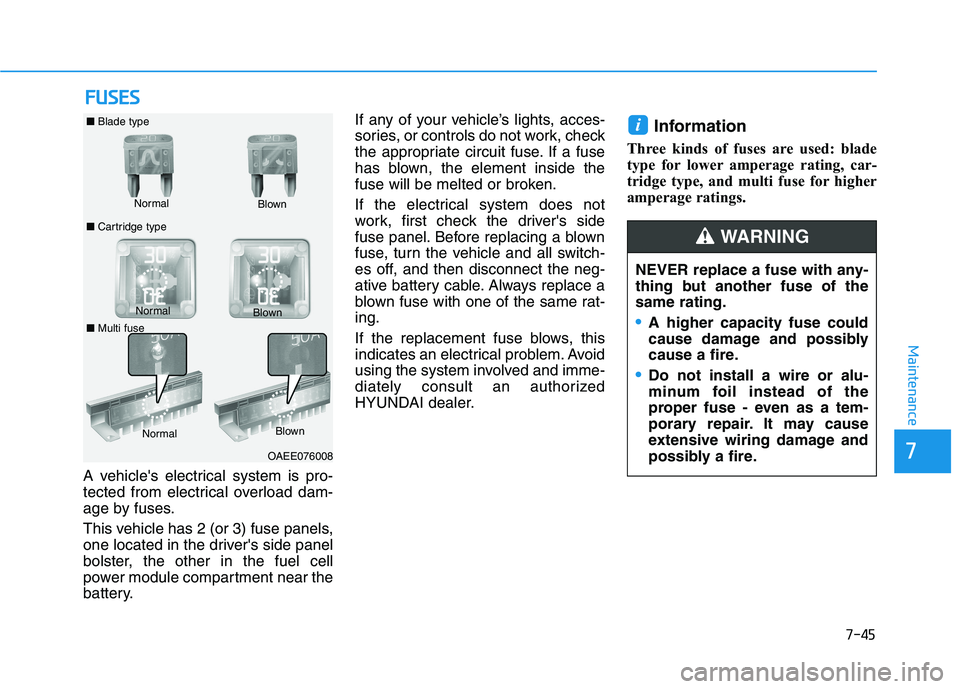
A vehicle's electrical system is pro-
tected from electrical overload dam-
age by fuses.
This vehicle has 2 (or 3) fuse panels,
one located in the driver's side panel
bolster, the other in the fuel cell
power module compartment near the
battery. If any of your vehicle’s lights, acces-
sories, or controls do not work, check
the appropriate circuit fuse. If a fuse
has blown, the element inside the
fuse will be melted or broken.
If the electrical system does not
work, first check the driver's side
fuse panel. Before replacing a blown
fuse, turn the vehicle and all switch-
es off, and then disconnect the neg-
ative battery cable. Always replace a
blown fuse with one of the same rat-
ing.
If the replacement fuse blows, this
indicates an electrical problem. Avoid
using the system involved and imme-
diately consult an authorized
HYUNDAI dealer.
Information
Three kinds of fuses are used: blade
type for lower amperage rating, car-
tridge type, and multi fuse for higher
amperage ratings.
i
NEVER replace a fuse with any-
thing but another fuse of the
same rating.
A higher capacity fuse could
cause damage and possibly
cause a fire.
Do not install a wire or alu-
minum foil instead of the
proper fuse - even as a tem-
porary repair. It may cause
extensive wiring damage and
possibly a fire.
WARNING
Normal
■
Blade type
■ Cartridge type Blown
Normal Blown
OAEE076008
Normal
Blown
■ Multi fuse
Page 475 of 561

7-50
Maintenance
Fuse NameFuse RatingProtected Component
MEMORY110APower Tail Gate Module, A/C Control Module, A/C Control Panel
MODULE110AICM Relay Box (Outside Mirror Folding/Unfolding Relay), A/V & Navigation Head Unit (Hazard Lamp Switch),
Shift Selection Switch (SBW), Auto Light & Photo Sensor, Driver/Passenger Power Outside Mirror,
Instrument Cluster
TAIL GATEOPEN10ATail Gate Relay
P/WINDOW RH25APower Window RH Relay
P/WINDOW LH25APower Window LH Relay, Driver Safety Window Module
P/SEAT DRV25ADriver Seat Manual Switch
MODULE47.5AIBU, Remote Control Smart Parking Assist Unit, VESS Unit, Electronic Parking Brake Switch,
Lane Keeping Assist Unit(Line), Blind-Spot Collision Warning Unit LH/RH, Crash Pad Switch,
PE Room Junction Block (Multipurpose Check Connector)
MODULE87.5AData Link Connector, Crash Pad Switch, Electro Chromic Mirror
S/HEATER RR20ARear Seat Heater
HEATED
MIRROR10ADriver/Passenger Power Outside Mirror, A/C Control Panel
S/HEATER FRT20AFront Air Ventilation/Seat Heater Seat Control Module
Instrument panel fuse panel
Page 482 of 561
7-57
7
Maintenance
L
LI
IG
G H
H T
T
B
B U
U L
LB
B S
S
Consult an authorized HYUNDAI
dealer to replace most vehicle light
bulbs. It is difficult to replace vehicle
light bulbs because other parts of the
vehicle must be removed before you
can get to the bulb. This is especially
true for removing the headlamp
assembly to get to the bulb(s).
Removing/installing the headlamp
assembly can result in damage to
the vehicle.
Information
The headlamp and tail lamp lenses
could appear frosty if the vehicle is
washed after driving or the vehicle is
driven at night in wet weather. This
condition is caused by temperature
difference between the lamp inside
and outside and, it does not indicate a
problem with your vehicle. When
moisture condenses in the lamp, it will
be removed after driving with the
headlamp on. The removable level
may differ depending on lamp size,
lamp position and environmental con-
dition. However, if moisture is not
removed, we recommend that your
vehicle is inspected by an authorized
HYUNDAI dealer.
Information
• A normally functioning lamp may
flicker momentarily to stabilize the
vehicle’s electrical control system.
However, if the lamp goes out after
flickering momentarily, or contin-
ues to flicker, we recommend the
system be checked by an authorized
HYUNDAI dealer.
• The parking lamp may not turn on when the parking lamp switch is
turned on, but the parking lamp
and headlamp switch may turn on
when the headlamp switch is turned
on. This may be caused by network
failure or vehicle electrical control
system malfunction. If this occurs,
we recommend the system be
checked by an authorized
HYUNDAI dealer.
i
i
•Prior to replacing a lamp, shift
to P (Park), apply the parking
brake, place the POWER but-
ton in the OFF position and
take the key with you when
leaving the vehicle to avoid
sudden movement of the vehi-
cle and to prevent possible
electric shock.
Be aware the bulbs may be
hot and may burn your fin-
gers.
WARNING
Page 486 of 561
7-61
7
Maintenance
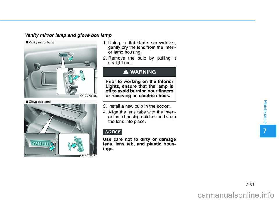
1. Using a flat-blade screwdriver,gently pry the lens from the interi-
or lamp housing.
2. Remove the bulb by pulling it straight out.
3. Install a new bulb in the socket.
4. Align the lens tabs with the interi- or lamp housing notches and snap
the lens into place.
Use care not to dirty or damage
lens, lens tab, and plastic hous-
ings.
NOTICE
Prior to working on the Interior
Lights, ensure that the lamp is
off to avoid burning your fingers
or receiving an electric shock.
WARNING
■ Vanity mirror lamp
■ Glove box lamp
OFE078035
OFE078037
Vanity mirror lamp and glove box lamp