Page 510 of 635
7-30
Maintenance
2. Lift up the wiper blade clip (1).
Then lift up the wiper blade (2).3. While pushing the lock (3), pull
down the wiper blade (4).4. Remove the wiper blade from the
wiper arm (5).
5. Install a new wiper blade assem-
bly in the reverse order of removal.
6. Return the wiper arm on the wind-
shield.
OAD075074LOAD075075LOAD075076L
Page 513 of 635

By jump starting
After a jump start from a good bat-
tery, drive the vehicle for 20-30 min-
utes before it is shutoff. The vehicle
may not restart if you shut it off
before the battery had a chance to
adequately recharge. See "Jump
Starting" in chapter 6 for more infor-
mation on jump starting procedures.
Information
An inappropriately disposed
battery can be harmful to
the environment and human
health. Dispose of the bat-
tery according to your local
law(s) or regulations.
Reset Features
The following items may need to be
reset after the battery has been dis-
charged or the battery has been dis-
connected. See chapter 3 or 4 for:
Power Windows
Trip Computer
Climate Control System
Clock
Audio System
Sunroof
Driver Position Memory System
i
7-33
7
Maintenance
(Continued)
Watch the battery during
charging, and stop or reduce
the charging rate if the battery
cells begin boiling violently.
The negative battery cable
must be removed first and
installed last when the battery
is disconnected. Disconnect
the battery charger in the fol-
lowing order:
(1) Turn off the battery charg-
er main switch.
(2) Unhook the negative
clamp from the negative
battery terminal.
(3) Unhook the positive clamp
from the positive battery
terminal.
Always use a genuine
HYUNDAI approved battery
when you replace the battery.
Page 514 of 635

7-34
Maintenance
T TI
IR
RE
ES
S
A
AN
ND
D
W
WH
HE
EE
EL
LS
S
Tire Care
For proper maintenance, safety, and
maximum fuel economy, you must
always maintain recommended tire
inflation pressures and stay within
the load limits and weight distribution
recommended for your vehicle. (Continued)Replace tires that are worn,
show uneven wear, or are dam-
aged. Worn tires can cause
loss of braking effectiveness,
steering control, or traction.
ALWAYS replace tires with the
same size as each tire that
was originally supplied with
this vehicle. Using tires and
wheels other than the recom-
mended sizes could cause
unusual handling characteris-
tics, poor vehicle control, or
negatively affect your vehi-
cle's Anti-Lock Brake System
(ABS) resulting in a serious
accident.
Tire failure may cause loss of
vehicle control resulting in an
accident. To reduce risk of
SERIOUS INJURY or DEATH,
take the following precautions:
Inspect your tires monthly for
proper inflation as well as
wear and damage.
The recommended cold tire
pressure for your vehicle can
be found in this manual and on
the tire label located on the dri-
ver's side center pillar. Always
use a tire pressure gauge to
measure tire pressure. Tires
with too much or too little
pressure wear unevenly caus-
ing poor handling.
Check the pressure of the
spare every time you check
the pressure of the other tires
on your vehicle.
(Continued)
WARNING
Page 518 of 635

7-38
Maintenance
Wheel Alignment and Tire
Balance
The wheels on your vehicle were
aligned and balanced carefully at the
factory to give you the longest tire life
and best overall performance.
In most cases, you will not need to
have your wheels aligned again.
However, if you notice unusual tire
wear or your vehicle pulling one way
or the other, the alignment may need
to be reset.
If you notice your vehicle vibrating
when driving on a smooth road, your
wheels may need to be rebalanced.
Improper wheel weights can dam-
age your vehicle's aluminum
wheels. Use only approved wheel
weights.
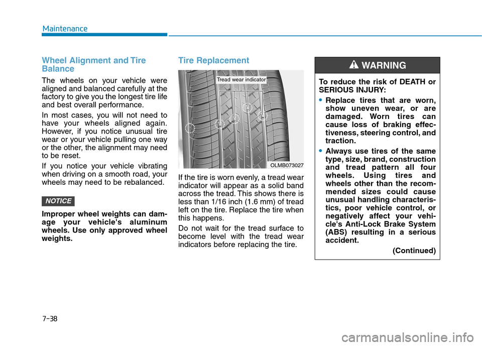
Tire Replacement
If the tire is worn evenly, a tread wear
indicator will appear as a solid band
across the tread. This shows there is
less than 1/16 inch (1.6 mm) of tread
left on the tire. Replace the tire when
this happens.
Do not wait for the tread surface to
become level with the tread wear
indicators before replacing the tire.
NOTICE
OLMB073027
Tread wear indicatorTo reduce the risk of DEATH or
SERIOUS INJURY:
Replace tires that are worn,
show uneven wear, or are
damaged. Worn tires can
cause loss of braking effec-
tiveness, steering control, and
traction.
Always use tires of the same
type, size, brand, construction
and tread pattern all four
wheels. Using tires and
wheels other than the recom-
mended sizes could cause
unusual handling characteris-
tics, poor vehicle control, or
negatively affect your vehi-
cle's Anti-Lock Brake System
(ABS) resulting in a serious
accident.
(Continued)
WARNING
Page 531 of 635
7-51
7
Maintenance
Fuse switch
Always, place the fuse switch to the
ON position.
If you move the switch to the OFF
position, some items such as the
audio system and digital clock must
be reset and the smart key may not
work properly.
Information
If the fuse switch is OFF, "Turn on
FUSE SWITCH" or "Turn FUSE
SWTICH On" message will appear. Always place the fuse switch in
the ON position while driving the
vehicle.
Do not move the fuse switch
repeatedly. The fuse switch may
be damaged.
NOTICEi
OAEPH078019OIK057165L/OIK057135L
Page 536 of 635

7-56
Maintenance
Always handle them carefully, and
avoid scratches and abrasions. If
the bulbs are lit, avoid contact with
liquids.
Never touch the glass with bare
hands. Residual oil may cause the
bulb to overheat and burst when lit.
A bulb should be operated only
when installed in a headlamp.
If a bulb becomes damaged or
cracked, replace it immediately
and carefully dispose of it.
Headlamp and parking lamp
1. Open the hood.
2. Disconnect the negative battery
cable.
3. Remove the headlamp bulb cover
(1) by turning it counterclockwise.
4. Disconnect the headlamp bulb
socket-connector. (for low beam
and high beam)
5. Remove the bulb from the head-
lamp assembly.
6. Install a new bulb. Halogen bulb
Handle halogen bulbs with
care. Halogen bulbs contain
pressurized gas that will pro-
duce flying pieces of glass
that could cause injuries if
broken.
Wear eye protection when
changing a bulb. Allow the
bulb to cool down before han-
dling it.
WARNING
OAE076052
OAE076030
Parking lampLow beam
High beam
Page 537 of 635

7-57
7
Maintenance
7. Connect the headlamp bulb sock-
et-connector. (for low beam and
high beam)
8. Install the hbulb cover (1) by turn-
ing it clockwise.
Information
The headlamp aiming should be
adjusted after an accident or after the
headlamp assembly is reinstalled at an
authorized HYUNDAI dealer.
Turn signal
1. Open the hood.
2. Disconnect the negative battery
cable.
3. Remove the socket from the
assembly by turning the socket
counterclockwise until the tabs on
the socket align with the slots on
the assembly.
4. Remove the bulb from the socket
by pressing it in and rotating it
counterclockwise until the tabs on
the bulb align with the slots in the
socket. Pull the bulb out of the
socket.5. Install a new bulb by inserting it
into the socket and rotating it until
it locks into place.
6. Install the socket into the assem-
bly by aligning the tabs on the
socket with the slots in the assem-
bly.
7. Push the socket into the assembly
and turn the socket clockwise.
i
OAE076031
Page 538 of 635
7-58
Maintenance
Side marker
1. Open the hood.
2. Disconnect the negative battery
cable.
3. Remove the socket from the
assembly by turning the socket
counterclockwise until the tabs on
the socket align with the slots on
the assembly.
4. Remove the bulb from the socket
by pulling out the bulb.
5. Insert a new bulb.
Type B
(1) Headlamp (high)
(2) Headlamp (low)
(3) Turn signal lamp
(4) Parking lamp
(5) Side marker lamp
Headlamp, parking lamp and side
marker lamp
If the light bulb does not operate, we
recommend that you have the vehi-
cle checked by an authorized
HYUNDAI dealer.
OAEPH077075N
OAE078052
HID headlamp
Do not attempt to replace or
inspect the low beam (XENON
bulb) due to electric shock dan-
ger. If the low beam (XENON
bulb) is not working, have your
vehicle checked by an author-
ized HYUNDAI Dealer.
WARNING