Page 371 of 561

5-135
Driving your vehicle
5
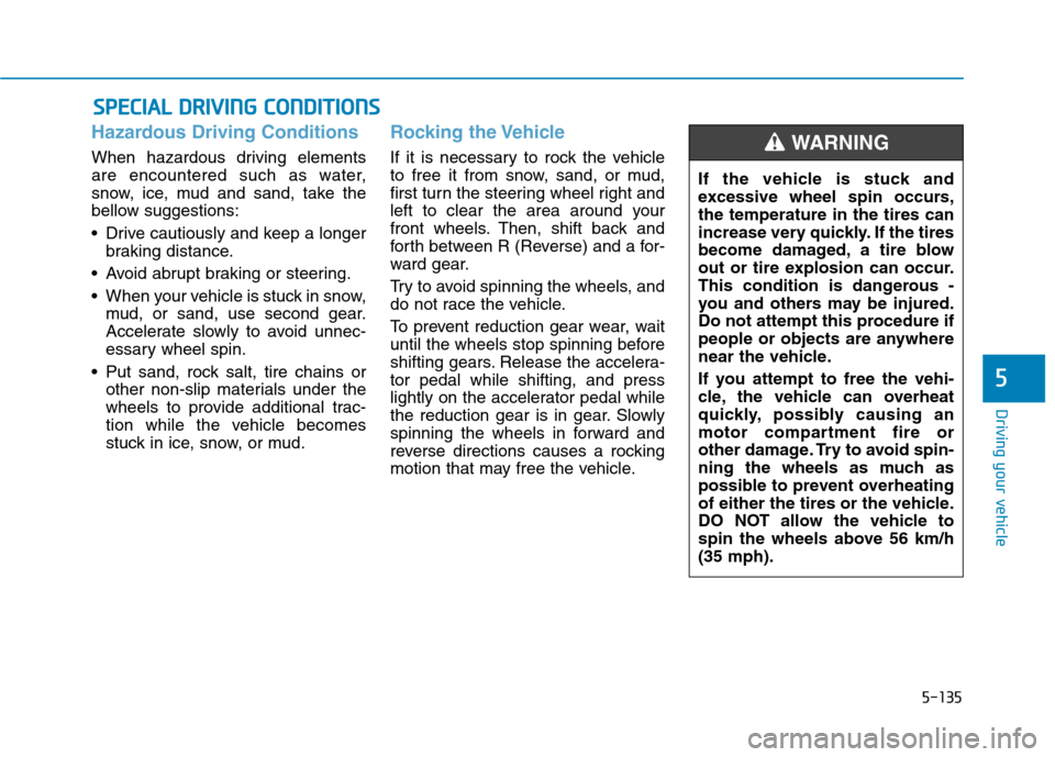
Hazardous Driving Conditions
When hazardous driving elements
are encountered such as water,
snow, ice, mud and sand, take the
bellow suggestions:
Drive cautiously and keep a longer
braking distance.
Avoid abrupt braking or steering.
When your vehicle is stuck in snow,
mud, or sand, use second gear.
Accelerate slowly to avoid unnec-
essary wheel spin.
Put sand, rock salt, tire chains or
other non-slip materials under the
wheels to provide additional trac-
tion while the vehicle becomes
stuck in ice, snow, or mud.
Rocking the Vehicle
If it is necessary to rock the vehicle
to free it from snow, sand, or mud,
first turn the steering wheel right and
left to clear the area around your
front wheels. Then, shift back and
forth between R (Reverse) and a for-
ward gear.
Try to avoid spinning the wheels, and
do not race the vehicle.
To prevent reduction gear wear, wait
until the wheels stop spinning before
shifting gears. Release the accelera-
tor pedal while shifting, and press
lightly on the accelerator pedal while
the reduction gear is in gear. Slowly
spinning the wheels in forward and
reverse directions causes a rocking
motion that may free the vehicle.
S SP
PE
EC
CI
IA
AL
L
D
DR
RI
IV
VI
IN
NG
G
C
CO
ON
ND
DI
IT
TI
IO
ON
NS
S
If the vehicle is stuck and
excessive wheel spin occurs,
the temperature in the tires can
increase very quickly. If the tires
become damaged, a tire blow
out or tire explosion can occur.
This condition is dangerous -
you and others may be injured.
Do not attempt this procedure if
people or objects are anywhere
near the vehicle.
If you attempt to free the vehi-
cle, the vehicle can overheat
quickly, possibly causing an
motor compartment fire or
other damage. Try to avoid spin-
ning the wheels as much as
possible to prevent overheating
of either the tires or the vehicle.
DO NOT allow the vehicle to
spin the wheels above 56 km/h
(35 mph).
WARNING
Page 424 of 561
7-18
Maintenance
Type A
1. Raise the wiper arm and slightly
rotate the wiper blade assembly to
expose the plastic locking clip.
2. Press the clip (1) and slide the
blade assembly downward (2).
3. Lift it off the arm.
4. Install the blade assembly in the
reverse order of removal.
5. Return the wiper arm on the wind-
shield.
Type B
1. Raise the wiper arm.
OLF074017OLMB073020
Do not allow the wiper arm to
fall against the windshield,
since it may chip or crack the
windshield.
CAUTION
OLMB073021
OLMB073022
Page 466 of 561

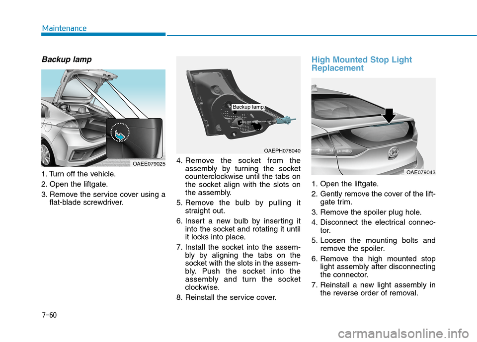
Backup lamp
1. Turn off the vehicle.
2. Open the liftgate.
3. Remove the service cover using a
flat-blade screwdriver.4. Remove the socket from the
assembly by turning the socket
counterclockwise until the tabs on
the socket align with the slots on
the assembly.
5. Remove the bulb by pulling it
straight out.
6. Insert a new bulb by inserting it
into the socket and rotating it until
it locks into place.
7. Install the socket into the assem-
bly by aligning the tabs on the
socket with the slots in the assem-
bly. Push the socket into the
assembly and turn the socket
clockwise.
8. Reinstall the service cover.
High Mounted Stop Light
Replacement
1. Open the liftgate.
2. Gently remove the cover of the lift-
gate trim.
3. Remove the spoiler plug hole.
4. Disconnect the electrical connec-
tor.
5. Loosen the mounting bolts and
remove the spoiler.
6. Remove the high mounted stop
light assembly after disconnecting
the connector.
7. Reinstall a new light assembly in
the reverse order of removal.
7-60
Maintenance
OAEPH078040
Backup lamp
OAE079043
OAEE079025
Page 467 of 561
7-61
7
Maintenance
License Plate Light Bulb
Replacement
1. Using a flat-blade screwdriver,
gently pry the lens cover from the
lamp housing.
2. Remove the bulb by pulling it
straight out.
3. Install a new bulb.
4. Reinstall in the reverse order.
Map lamp and room lamp
OAEE076026
■Map lamp (LED type)
OAEE076027
■Room lamp (LED type)
Interior Light Bulb Replacement
Your vehicle is equipped with LED lamps. LED lamps do not have replace-
able bulbs. If the LED lamp does not operate, have the vehicle checked by an
authorized HYUNDAI dealer.
OAE076044
Page 535 of 561

H47
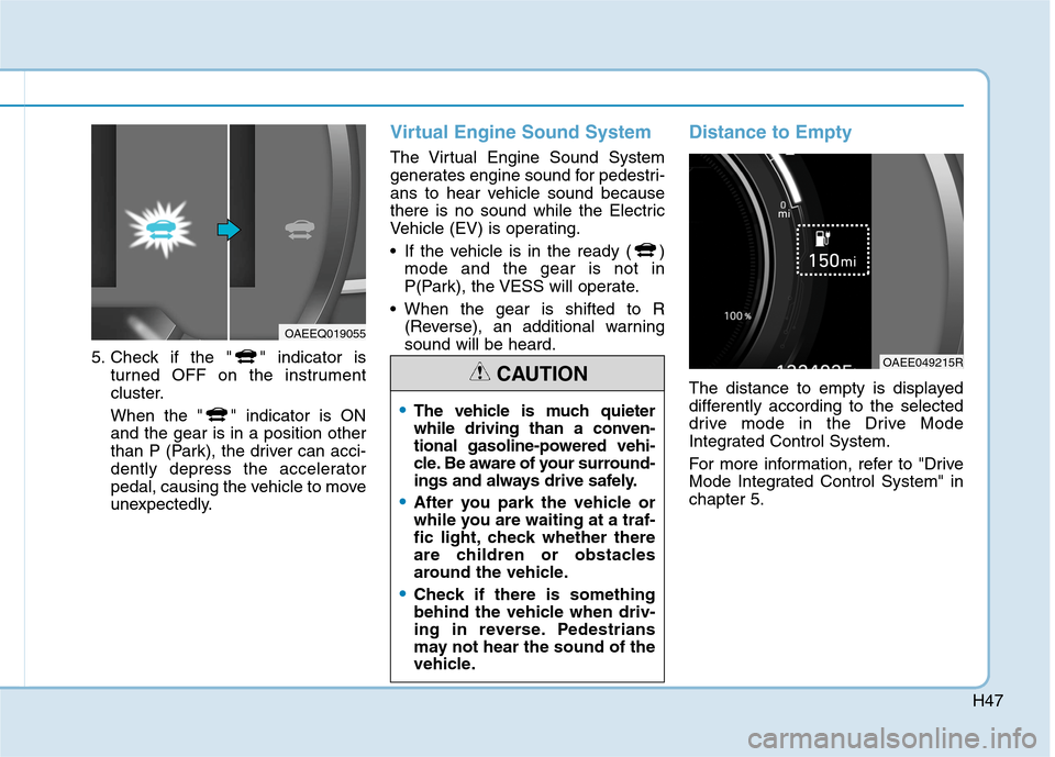
5. Check if the " " indicator is
turned OFF on the instrument
cluster.
When the " " indicator is ON
and the gear is in a position other
than P (Park), the driver can acci-
dently depress the accelerator
pedal, causing the vehicle to move
unexpectedly.
Virtual Engine Sound System
The Virtual Engine Sound System
generates engine sound for pedestri-
ans to hear vehicle sound because
there is no sound while the Electric
Vehicle (EV) is operating.
If the vehicle is in the ready ( )
mode and the gear is not in
P(Park), the VESS will operate.
When the gear is shifted to R
(Reverse), an additional warning
sound will be heard.
Distance to Empty
The distance to empty is displayed
differently according to the selected
drive mode in the Drive Mode
Integrated Control System.
For more information, refer to "Drive
Mode Integrated Control System" in
chapter 5.
OAEEQ019055
OAEE049215R
The vehicle is much quieter
while driving than a conven-
tional gasoline-powered vehi-
cle. Be aware of your surround-
ings and always drive safely.
After you park the vehicle or
while you are waiting at a traf-
fic light, check whether there
are children or obstacles
around the vehicle.
Check if there is something
behind the vehicle when driv-
ing in reverse. Pedestrians
may not hear the sound of the
vehicle.
CAUTION
Page 558 of 561

I-5
Power Outlet.............................................................3-139
Sunvisor ....................................................................3-139
Wireless Cellular Phone Charging System .............3-140
Interior Overview..............................................................1-4
Jump Starting (12V Battery) .............................................6-4
Lane Following Assist (LFA)........................................5-111
LFA operation ...........................................................5-113
Limitations of the system .........................................5-116
Warning message ......................................................5-114
Lane Keeping Assist (LKA) ...........................................5-62
Limitations of the System ..........................................5-68
LKA operation ............................................................5-64
LKA system function change .....................................5-70
Warning light and message ........................................5-67
LCD Display ..................................................................3-83
LCD Display Control .................................................3-83
LCD display modes ....................................................3-84
Light ..............................................................................3-101
Exterior Lights..........................................................3-101
Interior Lights...........................................................3-109
Welcome System .....................................................3-112Light Bulbs .....................................................................7-52
Daytime Running Light (DRL) ..................................7-57
Headlamp, Parking Lamp, Turn Signal Lamp and
Side Marker ..............................................................7-53
High Mounted Stop Light Replacement ....................7-60
Interior Light Bulb Replacement ...............................7-61
License Plate Light Bulb Replacement ......................7-61
Rear Combination Light Bulb Replacement ..............7-58
Side Repeater Lamp Replacement .............................7-58
Maintenance Services .......................................................7-4
Owner Maintenance Precautions..................................7-4
Owner's Responsibility.................................................7-4
Mirrors ............................................................................3-19
Inside Rearview Mirror ..............................................3-19
Reverse Parking Aid Function ..................................3-40
Side View Mirrors ....................................................3-37
Motor Compartment ..................................................1-6, 7-3
Motor Number ..................................................................8-8
Owner Maintenance ..........................................................7-5
Owner Maintenance Schedule......................................7-6
I
Index
J
L
M
O