2020 HONDA FIT charging
[x] Cancel search: chargingPage 13 of 599

11
Quick Reference Guide
Instrument Panel (P75)
Lights Indicators
Malfunction
Indicator Lamp
Low Oil Pressure
IndicatorAnti-lock Brake
System (ABS)
Indicator
Vehicle Stability
Assist
TM (VSA ®)
System Indicator
VSA ® OFF Indicator
Electric Power
Steering (EPS) System
Indicator Lights On Indicator High Beam Indicator
Immobilizer System
Indicator
Seat Belt Reminder
Indicator
System Indicators
CRUISE MAIN
Indicator*
Supplemental
Restraint System
Indicator
Door and Tailgate
Open Indicator
Tachometer
Speedometer
Fuel Gauge
Security System
Alarm Indicator
Shift Lever Position Indicator
*
Low Fuel Indicator
Gauges (P103)/Information Display* (P104) Multi-Information Display* (P107)/System Indicators (P76)
Turn Signal and
Hazard Warning
Indicators
High Temperature
Indicator (Red)
System Indicators
System Indicators
Low Tire Pressure/
TPMS Indicator
U.S. models only
Parking Brake
and Brake System
Indicator (Red)
CRUISE CONTROL
Indicator*
System Indicators
Charging System
Indicator
U.S.
Washer Level
Indicator*
ECON Mode
Indicator*
Maintenance
Minder Indicator
Fog Light Indicator
*
Canada
Brake System
Indicator (Amber)
Canada
U.S.
M
(7-speed manual shift mode)
Indicator/Shift Indicator*
Information Display
Models with information display
Low Temperature
Indicator (Blue)
* Not available on all models
20 FIT-31T5A6500.book 11 ページ 2019年9月26日 木曜日 午後4時41分
Page 14 of 599

12
Quick Reference Guide
Lights On Indicator
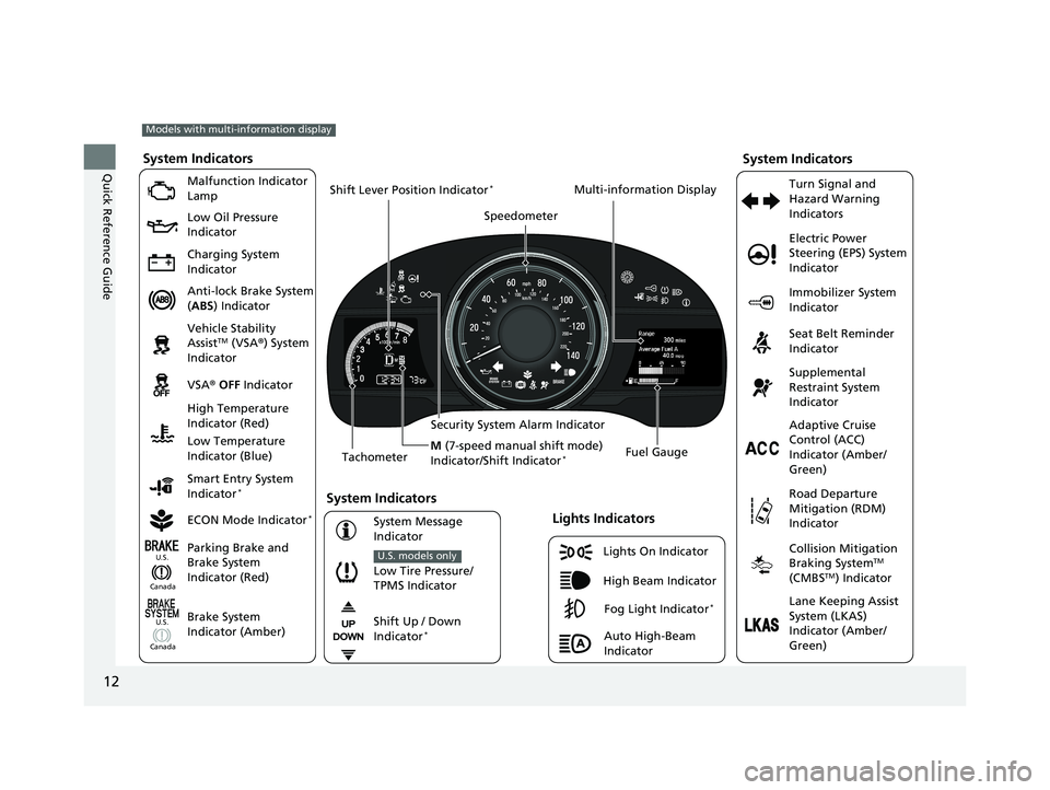
System Indicators
Malfunction Indicator
Lamp
Low Oil Pressure
Indicator
Charging System
Indicator
Anti-lock Brake System
(ABS ) Indicator
Vehicle Stability
Assist
TM (VSA ®) System
Indicator
VSA ® OFF Indicator
Low Tire Pressure/
TPMS Indicator
U.S. models only
Electric Power
Steering (EPS) System
Indicator
Seat Belt Reminder
Indicator
System Indicators
Parking Brake and
Brake System
Indicator (Red) Supplemental
Restraint System
Indicator
Tachometer Speedometer
Fuel Gauge
Security System Alarm Indicator
Shift Lever Position Indicator
*
Immobilizer System
Indicator
ECON Mode Indicator
*
Turn Signal and
Hazard Warning
Indicators
Models with multi-information display
Brake System
Indicator (Amber)
System Indicators
High Temperature
Indicator (Red)
Low Temperature
Indicator (Blue)
Lights Indicators
High Beam Indicator
Fog Light Indicator*
Adaptive Cruise
Control (ACC)
Indicator (Amber/
Green)
System Message
Indicator Collision Mitigation
Braking System
TM
(CMBSTM) Indicator
Road Departure
Mitigation (RDM)
Indicator
Lane Keeping Assist
System (LKAS)
Indicator (Amber/
Green)
Smart Entry System
Indicator
*
U.S.
Canada
Canada U.S.
Shift Up / Down
Indicator*
Multi-information Display
Auto High-Beam
Indicator
M
(7-speed manual shift mode)
Indicator/Shift Indicator
*
20 FIT-31T5A6500.book 12 ページ 2019年9月26日 木曜日 午後4時41分
Page 80 of 599

78
uuIndicators u
Instrument Panel
*1:Models with the smart entry system have an ENGINE START/STOP button instead of an ignition switch.
IndicatorNameOn/BlinkingExplanationMessage*
Charging System
Indicator
●Comes on when you turn the
ignition switch to ON
(w*1, and
goes off when the engine starts.
●Comes on when the battery is not
charging.
●Comes on while driving - Turn off the
heating and cooling system*/climate
control system* and rear defogger in
order to reduce electricity consumption.
2 If the Charging System Indicator
Comes On P. 562
Shift Lever
Position
Indicator
*
●Indicates the current shift lever
position.
2Shifting P. 417, 419—
Transmission
Indicator*
●Blinks if the transmission system
has a problem.●Blinks while driving - Avoid sudden
starts and acceleration and have your
vehicle checked by a dealer immediately.
* Not available on all models
20 FIT-31T5A6500.book 78 ページ 2019年9月26日 木曜日 午後4時41分
Page 209 of 599

207
uuAudio System uUSB Port(s)
Features
USB Port(s)
Install the iPod USB connector or the USB flash
drive to the USB port.
The USB port (1.0A) is for playing audio files
on a USB flash drive, connecting a cellular
phone and charging device.
The USB port (1.5A) is for charging devices,
playing audio files and connecting compatible
phones with Apple CarPlay
TM or Android
AutoTM.
u To prevent any potenti al issues, be sure
to use an Apple MFi Certified Lightning
Connector for Apple CarPlay, and for
Android Auto, the USB cables should be
certified by USB-IF to be compliant with
USB 2.0 Standard.
■In the consol e compartment*
The USB port (1.0A) is for playing audio files
on the USB flash drive and connecting a
cellular phone and charging device.
1USB Port(s)
•Do not leave the iPod or USB flash drive in the
vehicle. Direct sunlight and high temperatures may
damage it.
•We recommend that you us e a USB cable if you are
attaching a USB flash drive to the USB port.
•Do not connect the iPod or USB flash drive using a
hub.
•Do not use a device such as a card reader or hard
disk drive, as the device or your files may be
damaged.
•We recommend k eeping your data backed up
before using the device in your vehicle.
•Displayed messages may vary depending on the
device model and software version.
If the audio system does not recognize the iPod, try
reconnecting it a few times or reboot the device. To
reboot, follow the manufac turer’s instructions
provided with the iPod or visit www.apple.com/ipod.
The USB port can supply up to 1.5A of power. It does
not output 1.5A unless requested by the device.
For amperage details, read the operating manual of
the device that ne eds to be charged.
Under certain condi tions, a device connected to the
port may generate noise in the radio you are listening
to.
USB charge
Models
with
Display
Audio
Models
with
color
audio
system
Models with color audio system
Models with Display Audio
In the console compartment
* Not available on all models
20 FIT-31T5A6500.book 207 ページ 2019年9月26日 木曜日 午後4時41分
Page 305 of 599

303
uuAudio System Basic Operation uHonda App License Agreement
Continued
Features
E. Information Collection and Storage
1. Information Collection, Use, Transmission a nd Storage of Data. Consent to Use of Data:
You agree that HONDA and PROVIDERS may
collect and use your information gathered in any manner as part of product support services related to the SOFTWARE or related services.
HONDA may share such information with third parties, including, without limitation, PR OVIDERS, third party software and service s
suppliers, their affiliates and/or their designated agents, solely to improve their products or to provide services or technolo gies to you.
HONDA, third party software and systems supplie rs, their affiliates and/or their designated agent may disclose this information to others,
but not in a form that pe rsonally identifies you.
2. Information Storage.
Depending on the type of multimedia system you have in your VEHICLE, certain information may be stored for ease
of use of the SOFTWARE including, without limitation, search history, location history in certain applications, previous and sa ved
destinations, map locations within certain applications, and device numbers and contact information.
(a) Vehicle Health Information.
Your VEHICLE may remotely transmit information re garding the status and health of your VEHICLE
(“VEHICLE INFORMATION”) to HO NDA without notification to you. VEHICLE INFO RMATION may contain VEHICLE maintenance and
malfunction status that is derived from VEHICLE diagnostic data and includes, but is not limited to, status of powered doors and windows,
battery life data, battery charging data, VE HICLE speed, coolant temperature, air comp ressor revolution, output power, warning codes,
diagnostic trouble codes, fuel injection volume, and engine rota tions per minute. VEHICLE HEALTH INFORMATION may be used by HON DA
for research and development, to deliver HONDA SERVICES and informat ion to you, and to contact you, and is retained only for a period
of time necessary to fulfill these goals.
(b) VEHICLE Geolocation Data (non-navigation/map based).
If you opt-in to geolocation-based SERVICES, your vehicle’s geolocation data
(latitude and longitude) will be automatically sent from your VEHICLE to HONDA and PROVIDERS.
(c) You understand that the inputting or uploading of information to your VEHICLE’s multimedia system or the SOFTWARE or SERVIC ES is
at your own risk and that HONDA is not responsible for unauthori zed access to or use of any personal or other information. All information
uploaded to the SOFTWARE and SERVICES may be stored on your VEHICLES’s multimedia system and you understand that the security and
safety of your VEHICLE’s multimedia system is your sole responsibility.
20 FIT-31T5A6500.book 303 ページ 2019年9月26日 木曜日 午後4時41分
Page 537 of 599

535
uuBattery uCharging the Battery
Maintenance
Charging the Battery
Disconnect both battery cables to prevent damaging your vehicle’s electrical system.
Always disconnect the negative (–) cable first, and reconnect it last.1Battery
When you find corrosion, cl ean the battery terminals
by applying a baking powder and water solution.
Clean terminals with a damp towel. Cloth/towel dry
the battery. Coat the terminals with grease to help
prevent future corrosion.
20 FIT-31T5A6500.book 535 ページ 2019年9月26日 木曜日 午後4時41分
Page 547 of 599

545
Handling the Unexpected
This chapter explains how to handle unexpected troubles.
ToolsTypes of Tools .................................. 546
If a Tire Goes Flat Changing a Flat Tire ......................... 547
Engine Does Not Start Checking the Engine ........................ 554
If the Smart Entry Remote Battery is Weak.............................................................555
Emergency Engine Stop ................... 556
Jump Starting .................................... 557
Models with smart entry system
Models with smart entry system
Shift Lever Does Not Move .............. 559
Overheating How to Handle Overheating............. 560
Indicator, Coming On/Blinking If the Low Oil Pressure Indicator Comes On............................................................. 562
If the Charging System Indicator Comes On ................................................. 562
If the Malfunction Indicator Lamp Comes On or Blinks ..................................... 563
If the Brake System Indicator (Red) Comes On...................................................... 564 If the Electric Power Steering (EPS) System
Indicator Comes On ........................... 564
If the Low Tire Pressure/TPMS Indicator Comes On or Blinks ....................... 565
Fuses Fuse Locations ................................. 566
Inspecting and Changing Fuses ........ 570
Emergency Towing ........................... 571
When You Cannot Open the Tailgate..... 572
U.S. models
20 FIT-31T5A6500.book 545 ページ 2019年9月26日 木曜日 午後4時41分
Page 559 of 599

557Continued
Handling the Unexpected
Jump Starting
Turn off the power to electric devices, such as audio and lights. Turn off the engine,
then open the hood. 1.Connect the first jumper cable to your
vehicle’s battery + terminal.
u Remove the cover from the under-hood
fuse box.
2 Engine Compartment Fuse Box P. 566
2.Connect the other end of the first jumper
cable to the booster battery + terminal.
u Use a 12-volt booster battery only.
u Connect when using the automotive
battery charger to boost your 12-volt
battery, select a lower charging voltage
than 15-volt. Check the charger manual
for the proper setting.
3. Connect the second jumper cable to the
booster battery - terminal.
4. Connect the other end of the second
jumper cable to the stud bolt as shown. Do
not connect this jumper cable to any other
part.
5. If your vehicle is connected to another
vehicle, start the assisting vehicle’s engine
and increase its rpm slightly.
6. Attempt to start your ve hicle’s engine. If it
turns over slowly, check that the jumper
cables have good metal-to-metal contact.
■Jump Starting Procedure1 Jump Starting
Securely attach the jumper cables clips so that they
do not come off when the e ngine vibrates. Also be
careful not to tangle the ju mper cables or allow the
cable ends to touch each other while attaching or
detaching the jumper cables.
Battery performance degrades in cold conditions and
may prevent the engi ne from starting.
3WARNING
A battery can explode if you do not follow
the correct procedure, seriously injuring
anyone nearby.
Keep all sparks, open flames, and smoking
materials away from the battery.
Booster
Battery
20 FIT-31T5A6500.book 557 ページ 2019年9月26日 木曜日 午後4時41分