2020 GMC SIERRA DENALI wiring
[x] Cancel search: wiringPage 83 of 501

GMC Sierra/Sierra Denali Owner Manual (GMNA-Localizing-U.S./Canada/
Mexico-13337776) - 2020 - CRC - 8/27/19
82 Seats and Restraints
Warning (Continued)
seatback may interfere with the
proper operation of the passenger
sensing system.
Servicing the
Airbag-Equipped Vehicle
Airbags affect how the vehicle
should be serviced. There are parts
of the airbag system in several
places around the vehicle. Your
dealer and the service manual have
information about servicing the
vehicle and the airbag system. To
purchase a service manual, see
Publication Ordering Information
0471.
{Warning
For up to 10 seconds after the
vehicle is turned off and the
battery is disconnected, an airbag
can still inflate during improper
service. You can be injured if you
(Continued)
Warning (Continued)
are close to an airbag when it
inflates. Avoid yellow connectors.
They are probably part of the
airbag system. Be sure to follow
proper service procedures, and
make sure the person performing
work for you is qualified to do so.
Adding Equipment to the
Airbag-Equipped Vehicle
Adding accessories that change the
vehicle's frame, bumper system,
height, front end, or side sheet
metal, may keep the airbag system
from working properly.
The operation of the airbag system
can also be affected by changing,
including improperly repairing or
replacing, any parts of the following:
.Airbag system, including airbag
modules, front or side impact
sensors, sensing and diagnostic
module, or airbag wiring .
Front seats, including stitching,
seams, or zippers
. Seat belts
. Steering wheel, instrument
panel, overhead console, ceiling
trim, or pillar garnish trim
. Inner door seals, including
speakers
Your dealer and the service manual
have information about the location
of the airbag modules and sensors,
sensing and diagnostic module, and
airbag wiring along with the proper
replacement procedures.
In addition, the vehicle has a
passenger sensing system for the
front outboard passenger position,
which includes sensors that are part
of the passenger seat. The
passenger sensing system may not
operate properly if the original seat
trim is replaced with non-GM
covers, upholstery, or trim; or with
GM covers, upholstery, or trim
designed for a different vehicle. Any
object, such as an aftermarket seat
heater or a comfort-enhancing pad
or device, installed under or on top
Page 136 of 501

GMC Sierra/Sierra Denali Owner Manual (GMNA-Localizing-U.S./Canada/
Mexico-13337776) - 2020 - CRC - 8/27/19
Instruments and Controls 135
Seat Belt Reminders
Driver Seat Belt Reminder
Light
There is a driver seat belt reminder
light on the instrument cluster.
When the vehicle is started, this
light flashes and a chime may come
on to remind the driver to fasten
their seat belt. Then the light stays
on solid until the belt is buckled.
This cycle may continue several
times if the driver remains or
becomes unbuckled while the
vehicle is moving.
If the driver seat belt is buckled,
neither the light nor the chime
comes on.
Passenger Seat Belt Reminder
Light
There may be a passenger seat belt
reminder light near the passenger
airbag status indicator. See
Passenger Sensing System077.
For vehicles equipped with the
passenger seat belt reminder light,
when the vehicle is started this light
flashes and a chime may come on
to remind passengers to fasten their
seat belt. Then the light stays on
solid until the belt is buckled. This
cycle continues several times if the
passenger remains or becomes
unbuckled while the vehicle is
moving.
If the passenger seat belt is
buckled, neither the chime nor the
light comes on. The front passenger seat belt
reminder light and chime may turn
on if an object is put on the seat
such as a briefcase, handbag,
grocery bag, laptop, or other
electronic device. To turn off the
reminder light and/or chime, remove
the object from the seat or buckle
the seat belt.
Airbag Readiness Light
This light shows if there is an
electrical problem with the airbag
system. The system check includes
the airbag sensor(s), the passenger
sensing system, the pretensioners,
the airbag modules, the wiring, and
the crash sensing and diagnostic
module. For more information on the
airbag system, see
Airbag System
0 71.
Page 292 of 501
GMC Sierra/Sierra Denali Owner Manual (GMNA-Localizing-U.S./Canada/
Mexico-13337776) - 2020 - CRC - 8/27/19
Driving and Operating 291
Warning (Continued)
provide a means of escape
in the unlikely event the
vehicle slides into the water.
. If the boat launch surface is
slippery, have the driver
remain in the vehicle with
the brake pedal applied
while the boat is being
launched. The boat launch
can be especially slippery at
low tide when part of the
ramp was previously
submerged at high tide. Do
not back onto the ramp to
launch the boat if you are
not sure the vehicle can
maintain traction.
. Do not move the vehicle if
someone is in the path of
the trailer. Some parts of the
trailer might be underwater
and not visible to people
who are assisting in
launching the boat. Disconnect the wiring to the trailer
before backing the trailer into the
water to prevent damage to the
electrical circuits on the trailer.
Reconnect the wiring to the trailer
after removing the trailer from the
water. If the trailer has electric
brakes that can function when the
trailer is submerged, it might help to
leave the electrical trailer connector
attached to maintain trailer brake
functionality while on the boat ramp.
To back the trailer into the water:
1. If equipped, place the vehicle in four-wheel-drive high.
2. Slowly back down the boat ramp until the boat is floating,
but no further than necessary.
3. Press and hold the brake pedal, but do not shift into
P (Park) yet.
4. Have someone place chocks under the front wheels of the
vehicle.
5. Gradually release the brake pedal to allow the chocks to
absorb the load of the trailer. 6. Reapply the brake pedal. Then
apply the parking brake and
shift into P (Park).
7. Release the brake pedal.
Pulling the Trailer from the Water
To pull the trailer out of the water: 1. Press and hold the brake pedal.
2. Start the engine and shift into gear.
3. Release the parking brake.
4. Let up on the brake pedal.
5. Drive slowly until the tires are clear of the chocks.
6. Stop and have someone pick up and store the chocks.
7. Slowly pull the trailer from the water.
8. Once the vehicle and trailer have been driven from the
sloped part of the boat ramp,
the vehicle can be shifted from
four-wheel-drive high. Shift into
Page 302 of 501
GMC Sierra/Sierra Denali Owner Manual (GMNA-Localizing-U.S./Canada/
Mexico-13337776) - 2020 - CRC - 8/27/19
Driving and Operating 301
attaching points on the bumper;
otherwise, safety chains should be
attached to holes on the trailer hitch.
Cross the safety chains under the
tongue of the trailer to help prevent
the tongue from contacting the road
if it becomes separated from the
hitch. Always leave enough slack in
the safety chains to allow the
combination to turn. Never allow
safety chains to drag on the ground.
Trailer Brakes
Loaded trailers over 900 kg
(2,000 lb) must be equipped with
brake systems and with brakes for
each axle. Trailer braking equipment
conforming to Canadian Standards
Association (CSA) requirement
CAN3-D313, or its equivalent, is
recommended.
State or local regulations may
require trailers to have their own
braking system if the loaded weight
of the trailer exceeds certain
minimums that can vary from state
to state. Read and follow the
instructions for the trailer brakes so
they are installed, adjusted, andmaintained properly. Never attempt
to tap into your vehicle's hydraulic
brake system. If you do, both the
vehicle antilock brakes and the
trailer brakes may not function,
which could result in a crash.
Auxiliary Battery
If equipped, the vehicle's auxiliary
battery can be used to supply
electrical power to additional
equipment that may be added, such
as a slide-in camper.
Locate the auxiliary battery
connector under the hood on the
driver side of the vehicle, next to the
engine compartment fuse block.
Follow the proper installation
instructions included with any
electrical equipment that is installed.
Caution
To prevent draining the auxiliary
battery, always turn off electrical
equipment when not in use and
do not use any equipment that
(Continued)
Caution (Continued)
may exceed the
maximum amperage rating of
30 amps.
Trailer Wiring Harness
Basic Trailer Wiring
If the vehicle is not equipped with a
trailer connector on the rear bumper,
a 7-wire trailering harness is tied to
the vehicles frame. The harness
requires the installation of a trailer
connector, which is available
through your dealer.
Use only a round, seven-wire
connector with flat blade terminals
meeting SAE J2863 specifications
for proper electrical connectivity.
The seven-wire harness contains
the following trailer circuits:
Stop/Turn
Signal Left Yellow/Blue
Stop/Turn
Signal Right Green/Violet
Page 303 of 501
GMC Sierra/Sierra Denali Owner Manual (GMNA-Localizing-U.S./Canada/
Mexico-13337776) - 2020 - CRC - 8/27/19
302 Driving and Operating
Tail/Parking
LampsGray/Brown
Reverse Lamps White/Green
Battery Feed Red/Green
Ground White
Electric Trailer
Brake Blue
Heavy-Duty Trailer Wiring Harness
Package
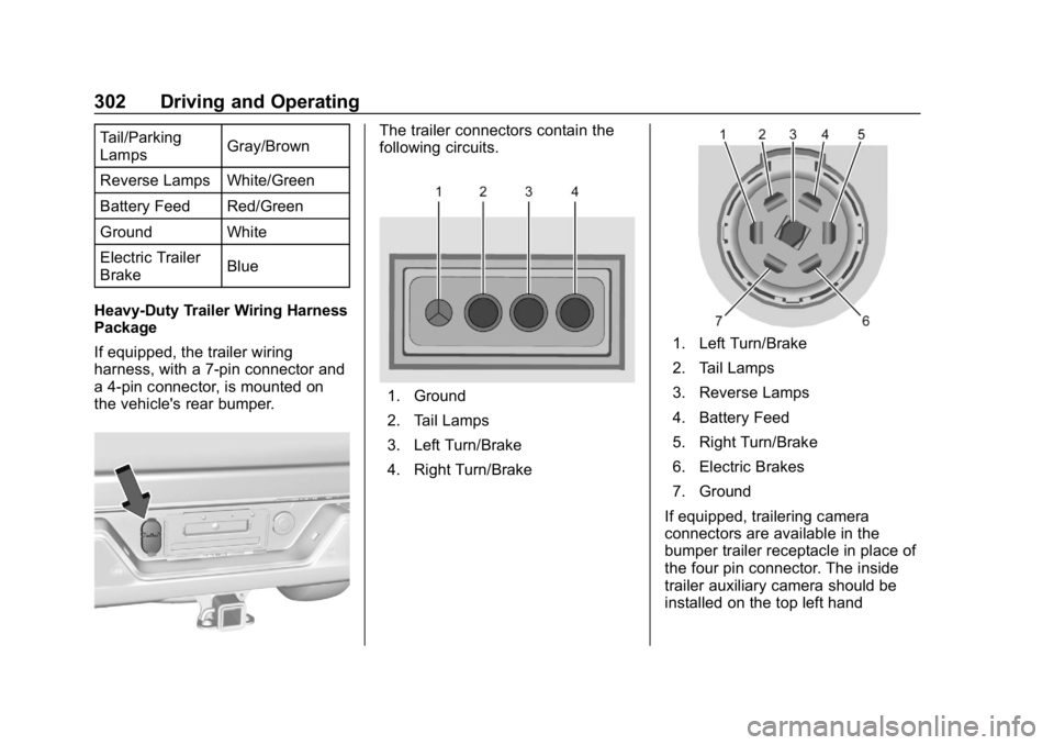
If equipped, the trailer wiring
harness, with a 7-pin connector and
a 4-pin connector, is mounted on
the vehicle's rear bumper.The trailer connectors contain the
following circuits.
1. Ground
2. Tail Lamps
3. Left Turn/Brake
4. Right Turn/Brake
1. Left Turn/Brake
2. Tail Lamps
3. Reverse Lamps
4. Battery Feed
5. Right Turn/Brake
6. Electric Brakes
7. Ground
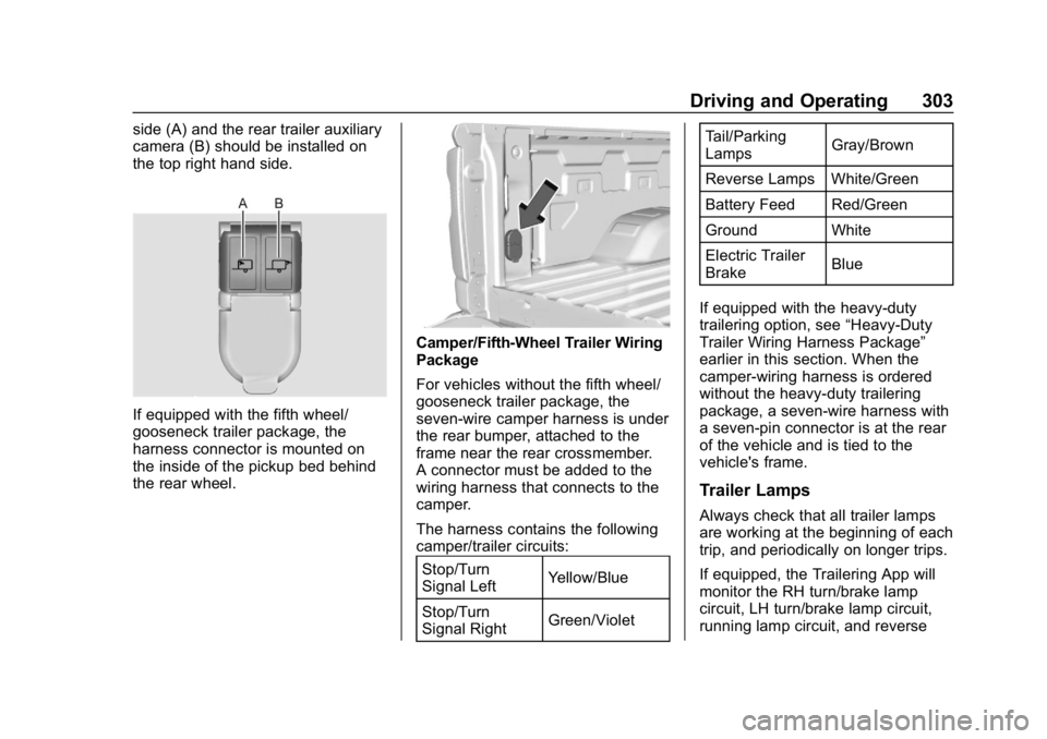
If equipped, trailering camera
connectors are available in the
bumper trailer receptacle in place of
the four pin connector. The inside
trailer auxiliary camera should be
installed on the top left hand
Page 304 of 501
GMC Sierra/Sierra Denali Owner Manual (GMNA-Localizing-U.S./Canada/
Mexico-13337776) - 2020 - CRC - 8/27/19
Driving and Operating 303
side (A) and the rear trailer auxiliary
camera (B) should be installed on
the top right hand side.
If equipped with the fifth wheel/
gooseneck trailer package, the
harness connector is mounted on
the inside of the pickup bed behind
the rear wheel.
Camper/Fifth-Wheel Trailer Wiring
Package
For vehicles without the fifth wheel/
gooseneck trailer package, the
seven-wire camper harness is under
the rear bumper, attached to the
frame near the rear crossmember.
A connector must be added to the
wiring harness that connects to the
camper.
The harness contains the following
camper/trailer circuits:Stop/Turn
Signal Left Yellow/Blue
Stop/Turn
Signal Right Green/Violet Tail/Parking
Lamps
Gray/Brown
Reverse Lamps White/Green
Battery Feed Red/Green
Ground White
Electric Trailer
Brake Blue
If equipped with the heavy-duty
trailering option, see “Heavy-Duty
Trailer Wiring Harness Package”
earlier in this section. When the
camper-wiring harness is ordered
without the heavy-duty trailering
package, a seven-wire harness with
a seven-pin connector is at the rear
of the vehicle and is tied to the
vehicle's frame.
Trailer Lamps
Always check that all trailer lamps
are working at the beginning of each
trip, and periodically on longer trips.
If equipped, the Trailering App will
monitor the RH turn/brake lamp
circuit, LH turn/brake lamp circuit,
running lamp circuit, and reverse
Page 307 of 501
GMC Sierra/Sierra Denali Owner Manual (GMNA-Localizing-U.S./Canada/
Mexico-13337776) - 2020 - CRC - 8/27/19
306 Driving and Operating
.Activate the Manual Trailer
Brake Apply Lever
TRAILER GAIN: Press a Trailer
Gain button to recall the current
Trailer Gain setting. Each press and
release of the gain buttons will then
change the Trailer Gain setting.
Press the Trailer Gain (+) or (-) to
adjust. Press and hold to
continuously adjust the Trailer Gain.
To turn the output to the trailer off,
adjust the Trailer Gain setting to 0.0.
This setting can be adjusted from
0.0 to 10.0 with a trailer connected
or disconnected.
TRAILER OUTPUT: This displays
anytime a trailer with electric brakes
is connected. Output to the trailer
brakes is based on the amount of
vehicle braking present and relative
to the Trailer Gain setting. Output is
displayed from 0 to 100% for each
gain setting.
The Trailer Output will indicate “- - -
- - -” on the Trailer Brake Display
Page whenever the following occur:
. No trailer is connected. .
A trailer without electric brakes
is connected. No DIC message
displays.
. A trailer with electric brakes has
become disconnected.
A CHECK TRAILER WIRING
message displays on the DIC.
. There is a fault present in the
wiring to the trailer brakes.
A CHECK TRAILER WIRING
message displays on the DIC.
. The ITBC system is not working
due to a fault. A SERVICE
TRAILER BRAKE SYSTEM
message displays in the DIC.
Manual Trailer Brake Apply
Lever
Slide this lever right to apply the
trailer ’s electric brakes independent
of the vehicle’s brakes. Use this
lever to adjust the Trailer Gain to
achieve proper power output to the
trailer brakes. Under certain
circumstances, this lever can also
be used to apply additional trailer
braking. The trailer and vehicle
brake lamps will come on when either the vehicle brakes or trailer
brakes are applied and properly
connected.
Trailer Gain Adjustment
Procedure
Trailer Gain should be set for a
specific trailering condition and it
must be readjusted anytime vehicle
loading, trailer loading, or road
surface conditions change.
{Warning
Trailer brakes that are
over-gained or under-gained may
not stop the vehicle and the trailer
as intended and can result in a
crash. Always follow the
instructions to set the Trailer Gain
for the proper trailer stopping
performance.
To adjust Trailer Gain for each
towing condition: 1. Drive the vehicle with the trailer attached on a level road
surface representative of the
Page 308 of 501
GMC Sierra/Sierra Denali Owner Manual (GMNA-Localizing-U.S./Canada/
Mexico-13337776) - 2020 - CRC - 8/27/19
Driving and Operating 307
towing condition and free of
traffic at about 32–40 km/h
(20–25 mph) and fully apply
the Manual Trailer Brake Apply
Lever.
Adjusting Trailer Gain at
speeds lower than 32–40 km/h
(20–25 mph) may result in an
incorrect gain setting.
2. Adjust the Trailer Gain, using the Trailer Gain (+) or (−)
adjustment buttons, to just
below the point of trailer wheel
lock-up, indicated by trailer
wheel squeal or tire smoke
when a trailer wheel locks.
Trailer wheel lock-up may not
occur if towing a heavily loaded
trailer. Adjust the Trailer Gain
to the highest allowable setting
for the towing condition.
3. Readjust Trailer Gain anytime vehicle loading, trailer loading,
or road surface conditions
change or if trailer wheel
lock-up is noticed at any time
while towing.Other ITBC-Related DIC
Messages
TRAILER CONNECTED: This
message will briefly display when a
trailer with electric brakes is first
connected to the vehicle. This
message will automatically turn off
in about 10 seconds. This message
can be acknowledged before it
automatically turns off.
CHECK TRAILER WIRING: This
message will display if:
.The ITBC system first
determines connection to a
trailer with electric brakes and
then the trailer harness becomes
disconnected from the vehicle.
If the disconnect occurs while
the vehicle is stationary, this
message will automatically turn
off in about 30 seconds. This
message will also turn off if it is
acknowledged or if the trailer
harness is reconnected.
If the disconnect occurs while
the vehicle is moving, this
message will continue until the
ignition is turned off. This message will also turn off if it is
acknowledged or if the trailer
harness is reconnected.
. There is an electrical fault in the
wiring to the trailer brakes. This
message will continue as long
as there is an electrical fault in
the trailer wiring. This message
will also turn off if it is
acknowledged.
To determine whether the electrical
fault is on the vehicle side or trailer
side of the trailer wiring harness
connection: 1. Disconnect the trailer wiring harness from the vehicle.
2. Turn the ignition off.
3. Wait 10 seconds, then turn the ignition back to RUN.
4. If the CHECK TRAILER WIRING message reappears,
the electrical fault is on the
vehicle side.