2020 DODGE GRAND CARAVAN spare tire location
[x] Cancel search: spare tire locationPage 6 of 380

4
ENGINE BREAK-IN RECOMMENDATIONS ...... 163
PARK BRAKE ..................................................... 164
AUTOMATIC TRANSMISSION............................ 165 Key Ignition Park Interlock ........................ 166Brake/Transmission Shift Interlock
System ........................................................ 166 Fuel Economy (ECON) Mode .....................167Six-Speed Automatic Transmission ..........167
Gear Ranges ..............................................168
POWER STEERING ............................................. 172
Power Steering Fluid Check ......................173
SPEED CONTROL — IF EQUIPPED .................... 173
To Activate .................................................. 174To Set A Desired Speed .............................174To Vary The Speed Setting ........................ 174To Accelerate For Passing ........................ 175To Resume Speed......................................175
To Deactivate .............................................175
PARKSENSE REAR PARK ASSIST
— IF EQUIPPED ................................................... 175
ParkSense Sensors ...................................176
ParkSense Warning Display ......................176
ParkSense Display ..................................... 176Enabling/Disabling ParkSense ................. 178
Service The ParkSense Rear Park Assist
System ........................................................ 178 Cleaning The ParkSense System ..............178
ParkSense System Usage Precautions ....178 PARKVIEW REAR BACK UP CAMERA ............. 179
REFUELING THE VEHICLE ................................. 181
Loose Fuel Filler Cap Message ................. 181
VEHICLE LOADING ............................................182
Certification Label ..................................... 182
TRAILER TOWING ............................................... 183
Common Towing Definitions ..................... 183Trailer Hitch Classification ........................ 184
Trailer Towing Weights
(Maximum Trailer Weight Ratings) .......... 186 Trailer And Tongue Weight ....................... 186
Towing Requirements ............................... 187Towing Tips ................................................ 189
RECREATIONAL TOWING
(BEHIND MOTORHOME, ETC.) .......................... 191
Towing This Vehicle Behind Another
Vehicle ........................................................ 191 Recreational Towing — All Models ............ 191
DRIVING TIPS ...................................................... 192
Driving On Slippery Surfaces .................... 192
Driving Through Water .............................. 192
IN CASE OF EMERGENCY
HAZARD WARNING FLASHERS .......................194
BULB REPLACEMENT ........................................ 194Replacement Bulbs .................................. 194Replacing Exterior Bulbs ........................... 196 FUSES .................................................................. 197
General Information .................................. 198
Totally Integrated Power Module
(Fuses) ....................................................... 198
JACKING AND TIRE CHANGING ....................... 202
Jack Location ............................................. 203
Spare Tire Tools ......................................... 203To Access Spare Tire Winch Drive Nut ..... 203Spare Tire Removal .................................. 205
Spare Tire Removal Instructions .............. 205
Preparations For Jacking ......................... 206
Jacking Instructions................................... 206
Securing The Compact Spare Tire ............ 210
Road Tire Installation ................................ 211
TIRE SERVICE KIT — IF EQUIPPED ................... 212
JUMP STARTING ................................................ 219
Preparations For Jump Start ..................... 219
Jump Starting Procedure .......................... 220
IF YOUR ENGINE OVERHEATS ......................... 221
GEAR SELECTOR OVERRIDE ........................... 222
FREEING A STUCK VEHICLE ............................. 223
TOWING A DISABLED VEHICLE ....................... 224
ENHANCED ACCIDENT RESPONSE
SYSTEM (EARS) ................................................. 225
EVENT DATA RECORDER (EDR) ....................... 225
20_RT_OM_EN_USC_t.book Page 4
Page 205 of 380

IN CASE OF EMERGENCY203
Jack Location
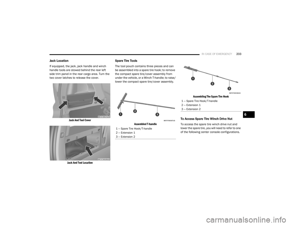
If equipped, the jack, jack handle and winch
handle tools are stowed behind the rear left
side trim panel in the rear cargo area. Turn the
two cover latches to release the cover.
Jack And Tool Cover
Jack And Tool Location
Spare Tire Tools
The tool pouch contains three pieces and can
be assembled into a spare tire hook; to remove
the compact spare tire/cover assembly from
under the vehicle, or a Winch T-handle; to raise/
lower the compact spare tire/cover assembly.
Assembled T-handle Assembling The Spare Tire Hook
To Access Spare Tire Winch Drive Nut
To access the spare tire winch drive nut and
lower the spare tire, you will need to refer to one
of the following center console configurations.
1 — Spare Tire Hook/T-handle
2 — Extension 1
3 — Extension 2
1 — Spare Tire Hook/T-handle
2 — Extension 1
3 — Extension 2
6
20_RT_OM_EN_USC_t.book Page 203
Page 206 of 380

204IN CASE OF EMERGENCY
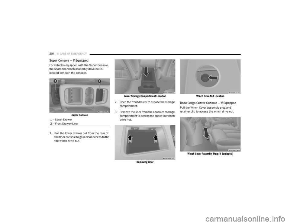
Super Console — If Equipped
For vehicles equipped with the Super Console,
the spare tire winch assembly drive nut is
located beneath the console.
Super Console
1. Pull the lower drawer out from the rear of the floor console to gain clear access to the
tire winch drive nut.
Lower Storage Compartment Location
2. Open the front drawer to expose the storage compartment.
3. Remove the liner from the consoles storage compartment to access the spare tire winch
drive nut.
Removing Liner Winch Drive Nut Location
Base Cargo Center Console — If Equipped
Pull the Winch Cover assembly plug and
retainer clip to access the winch drive nut.
Winch Cover Assembly Plug (If Equipped)
1 — Lower Drawer
2 — Front Drawer/Liner
20_RT_OM_EN_USC_t.book Page 204
Page 207 of 380

IN CASE OF EMERGENCY205
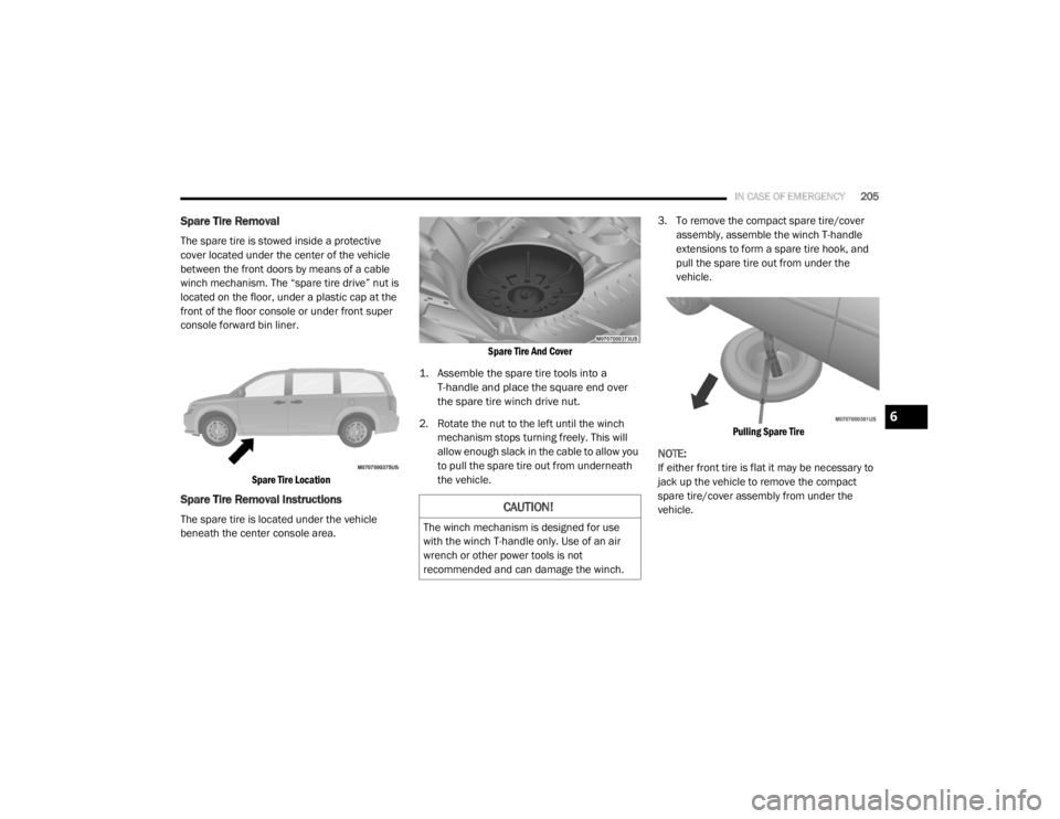
Spare Tire Removal
The spare tire is stowed inside a protective
cover located under the center of the vehicle
between the front doors by means of a cable
winch mechanism. The “spare tire drive” nut is
located on the floor, under a plastic cap at the
front of the floor console or under front super
console forward bin liner.
Spare Tire Location
Spare Tire Removal Instructions
The spare tire is located under the vehicle
beneath the center console area.
Spare Tire And Cover
1. Assemble the spare tire tools into a T-handle and place the square end over
the spare tire winch drive nut.
2. Rotate the nut to the left until the winch mechanism stops turning freely. This will
allow enough slack in the cable to allow you
to pull the spare tire out from underneath
the vehicle. 3. To remove the compact spare tire/cover
assembly, assemble the winch T-handle
extensions to form a spare tire hook, and
pull the spare tire out from under the
vehicle.
Pulling Spare Tire
NOTE:
If either front tire is flat it may be necessary to
jack up the vehicle to remove the compact
spare tire/cover assembly from under the
vehicle.CAUTION!
The winch mechanism is designed for use
with the winch T-handle only. Use of an air
wrench or other power tools is not
recommended and can damage the winch.
6
20_RT_OM_EN_USC_t.book Page 205
Page 209 of 380

IN CASE OF EMERGENCY207
Jack Warning Label
NOTE:
Refer to the “Compact Spare Tire” section of
“Tires” in “Servicing And Maintenance” for
information about the compact spare tire, its
use, and operation.
1. Loosen (but do not remove) the wheel lug
nuts by turning them to the left one turn
while the wheel is still on the ground.
2. There are two jack engagement locations on each side of the vehicle body. These
locations are on the sill flange of the vehicle
body.
Jack Locations
Apply the parking brake firmly and shift an
automatic transmission to PARK; a manual
transmission to REVERSE.
Block the wheel diagonally opposite the
wheel to be raised.
Never start or run the engine with the
vehicle on a jack.
Do not let anyone sit in the vehicle when it
is on a jack.
Do not get under the vehicle when it is on a
jack. If you need to get under a raised
vehicle, take it to a service center where it
can be raised on a lift.
Only use the jack in the positions indicated
and for lifting this vehicle during a tire
change.
If working on or near a roadway, be
extremely careful of motor traffic.
To assure that spare tires, flat or inflated,
are securely stowed, spares must be
stowed with the valve stem facing the
ground.
WARNING! (Continued)
CAUTION!
Do not attempt to raise the vehicle by jacking
on locations other than those indicated in the
Jacking Instructions for this vehicle.
CAUTION!
Do not attempt to raise the vehicle by jacking
on locations other than those indicated.
6
20_RT_OM_EN_USC_t.book Page 207
Page 210 of 380

208IN CASE OF EMERGENCY
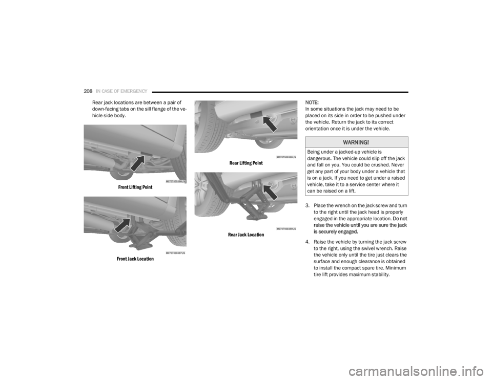
Rear jack locations are between a pair of
down-facing tabs on the sill flange of the ve -
hicle side body.
Front Lifting Point
Front Jack Location Rear Lifting Point
Rear Jack Location
NOTE:
In some situations the jack may need to be
placed on its side in order to be pushed under
the vehicle. Return the jack to its correct
orientation once it is under the vehicle.
3. Place the wrench on the jack screw and turn
to the right until the jack head is properly
engaged in the appropriate location. Do not
raise the vehicle until you are sure the jack
is securely engaged.
4. Raise the vehicle by turning the jack screw to the right, using the swivel wrench. Raise
the vehicle only until the tire just clears the
surface and enough clearance is obtained
to install the compact spare tire. Minimum
tire lift provides maximum stability.
WARNING!
Being under a jacked-up vehicle is
dangerous. The vehicle could slip off the jack
and fall on you. You could be crushed. Never
get any part of your body under a vehicle that
is on a jack. If you need to get under a raised
vehicle, take it to a service center where it
can be raised on a lift.
20_RT_OM_EN_USC_t.book Page 208
Page 212 of 380

210IN CASE OF EMERGENCY
10. Place the deflated (flat) tire and compact
spare tire cover assembly in the rear cargo
area. Do not stow the deflated tire in the
compact spare tire location. Have the
full-sized tire repaired or replaced, as soon
as possible.
11. Stow the cable and wheel spacer before driving the vehicle. Reassemble the winch
handle extensions to form a “T” and fit the
winch T-handle over the drive nut. Rotate
the nut to the right until the winch
mechanism clicks at least three times.
NOTE:
Refer to the “Spare Tire Tools” section for
instructions on assembling the T-handle.
12. Stow the jack, jack handle and winch handle tools back in the stowage
compartment.
13. Check the compact spare tire pressure as soon as possible. Correct the tire pressure,
as required.Securing The Compact Spare Tire
1. Assemble the winch handle extensions to form a T-handle and fit the winch T-handle
over the drive nut. Rotate the nut to the left
until the winch mechanism stops turning
freely. This will allow enough slack in the
cable to allow you to pull the wheel spacer
out from under the vehicle.
2. Assemble the winch handle extensions to form the spare tire hook, and pull the wheel
spacer from under the vehicle. 3. Turn the compact spare tire so that the
valve stem is down, and place the tire into
the compact spare tire/cover assembly.
Slide the wheel spacer through the center of
the wheel and compact spare tire/cover
assembly, so that the two retainer tabs
snap out and engage the compact spare tire
cover on the opposite side.
WARNING!
A loose compact spare tire/cover assembly,
thrown forward in a collision or hard stop
could endanger the occupants of the vehicle.
Always stow the compact spare tire with the
cover assembly in the place provided.
CAUTION!
The winch mechanism is designed for use
with the winch T-handle only. Use of an air
wrench or other power tools is not
recommended and can damage the winch.
WARNING!
Verify that both retainer tabs of the wheel
spacer have been properly extended through
the center of the wheel and compact spare
tire/cover assembly. Failure to properly
engage both retainer tabs could result in loss
of the compact spare tire and cover
assembly, which will cause vehicle damage
and may cause loss of vehicle control and
serious personal injury.
CAUTION!
The compact spare tire/cover assembly must
be used when the compact spare tire is
stored. Failure to use this cover could
drastically reduce the life of the compact
spare tire.
20_RT_OM_EN_USC_t.book Page 210
Page 251 of 380

SERVICING AND MAINTENANCE249
Tire Loading And Tire Pressure
NOTE:
The proper cold tire inflation pressure is listed
on the driver’s side B-Pillar or the rear edge of
the driver's side door.
Check the inflation pressure of each tire,
including the spare tire (if equipped), at least
monthly and inflate to the recommended
pressure for your vehicle.
Example Tire Placard Location (Door) Example Tire Placard Location (B-Pillar)
Tire And Loading Information Placard
Tire And Loading Information Placard
This placard tells you important information
about the:
1. Number of people that can be carried in
the vehicle.
2. Total weight your vehicle can carry.
3. Tire size designed for your vehicle.
4. Cold tire inflation pressures for the front, rear, and spare tires.
Loading
The vehicle maximum load on the tire must not
exceed the load carrying capacity of the tire on
your vehicle. You will not exceed the tire's load
carrying capacity if you adhere to the loading
conditions, tire size, and cold tire inflation
pressures specified on the Tire and Loading
Information placard in “Vehicle Loading” in the
“Starting And Operating” section of this manual.
NOTE:
Under a maximum loaded vehicle condition,
gross axle weight ratings (GAWRs) for the front
and rear axles must not be exceeded.
7
20_RT_OM_EN_USC_t.book Page 249