2020 DODGE GRAND CARAVAN cargo
[x] Cancel search: cargoPage 189 of 380

STARTING AND OPERATING187
(Continued)
Consider the following items when computing
the weight on the rear axle of the vehicle:
The tongue weight of the trailer.
The weight of any other type of cargo or
equipment put in or on your vehicle.
The weight of the driver and all passengers.
NOTE:
Remember that everything put into or on the
trailer adds to the load on your vehicle. Also,
additional factory-installed options or
dealer-installed options must be considered as
part of the total load on your vehicle. Refer to
the “Tire And Loading Information” placard for
the maximum combined weight of occupants
and cargo for your vehicle.
Towing Requirements
To promote proper break-in of your new vehicle
drivetrain components, the following guidelines
are recommended. Perform the maintenance listed in the
“Scheduled Servicing”. Refer to “Scheduled
Servicing” in “Servicing And Maintenance” for
the proper maintenance intervals. When towing
a trailer, never exceed the GAWR or GCWR
ratings.
CAUTION!
Do not tow a trailer at all during the first
500 miles (805 km) the new vehicle is
driven. The engine, axle or other parts could
be damaged.
Then, during the first 500 miles (805 km) that a trailer is towed, do not drive over
50 mph (80 km/h) and do not make starts
at full throttle. This helps the engine and
other parts of the vehicle wear in at the
heavier loads.
WARNING!
Make certain that the load is secured in the
trailer and will not shift during travel. When
trailering cargo that is not fully secured,
dynamic load shifts can occur that may be
difficult for the driver to control. You could
lose control of your vehicle and have a
collision.
When hauling cargo or towing a trailer, do
not overload your vehicle or trailer. Over -
loading can cause a loss of control, poor
performance or damage to brakes, axle,
engine, transmission, steering, suspension,
chassis structure or tires.
Safety chains must always be used
between your vehicle and trailer. Always
connect the chains to the hook retainers of
the vehicle hitch. Cross the chains under
the trailer tongue and allow enough slack
for turning corners.
5
20_RT_OM_EN_USC_t.book Page 187
Page 205 of 380

IN CASE OF EMERGENCY203
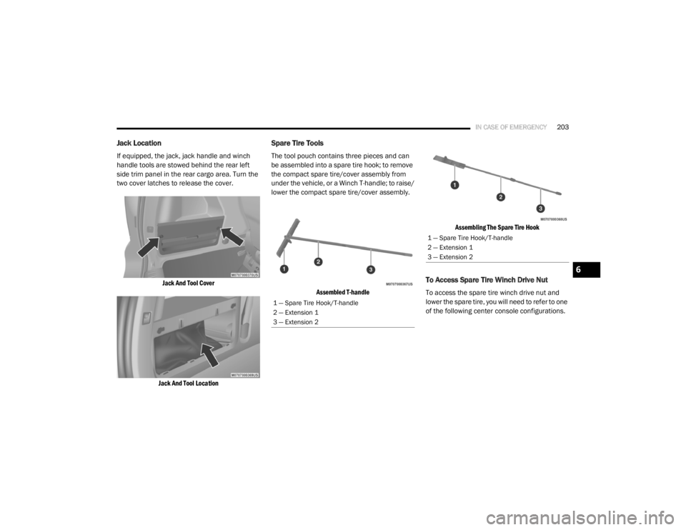
Jack Location
If equipped, the jack, jack handle and winch
handle tools are stowed behind the rear left
side trim panel in the rear cargo area. Turn the
two cover latches to release the cover.
Jack And Tool Cover
Jack And Tool Location
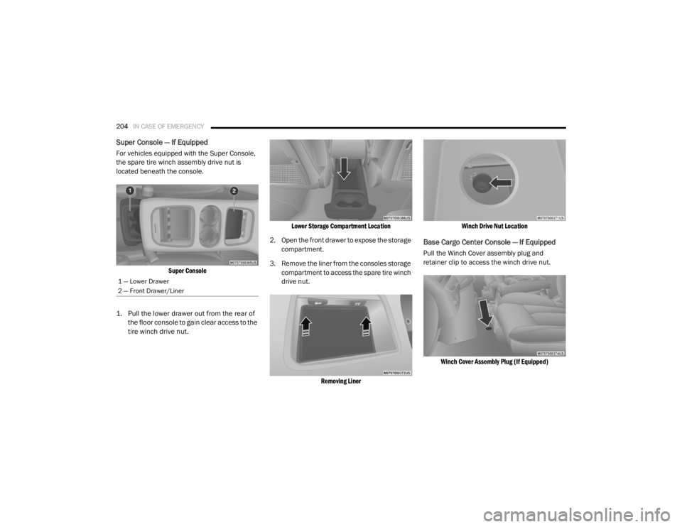
Spare Tire Tools
The tool pouch contains three pieces and can
be assembled into a spare tire hook; to remove
the compact spare tire/cover assembly from
under the vehicle, or a Winch T-handle; to raise/
lower the compact spare tire/cover assembly.
Assembled T-handle Assembling The Spare Tire Hook
To Access Spare Tire Winch Drive Nut
To access the spare tire winch drive nut and
lower the spare tire, you will need to refer to one
of the following center console configurations.
1 — Spare Tire Hook/T-handle
2 — Extension 1
3 — Extension 2
1 — Spare Tire Hook/T-handle
2 — Extension 1
3 — Extension 2
6
20_RT_OM_EN_USC_t.book Page 203
Page 206 of 380

204IN CASE OF EMERGENCY
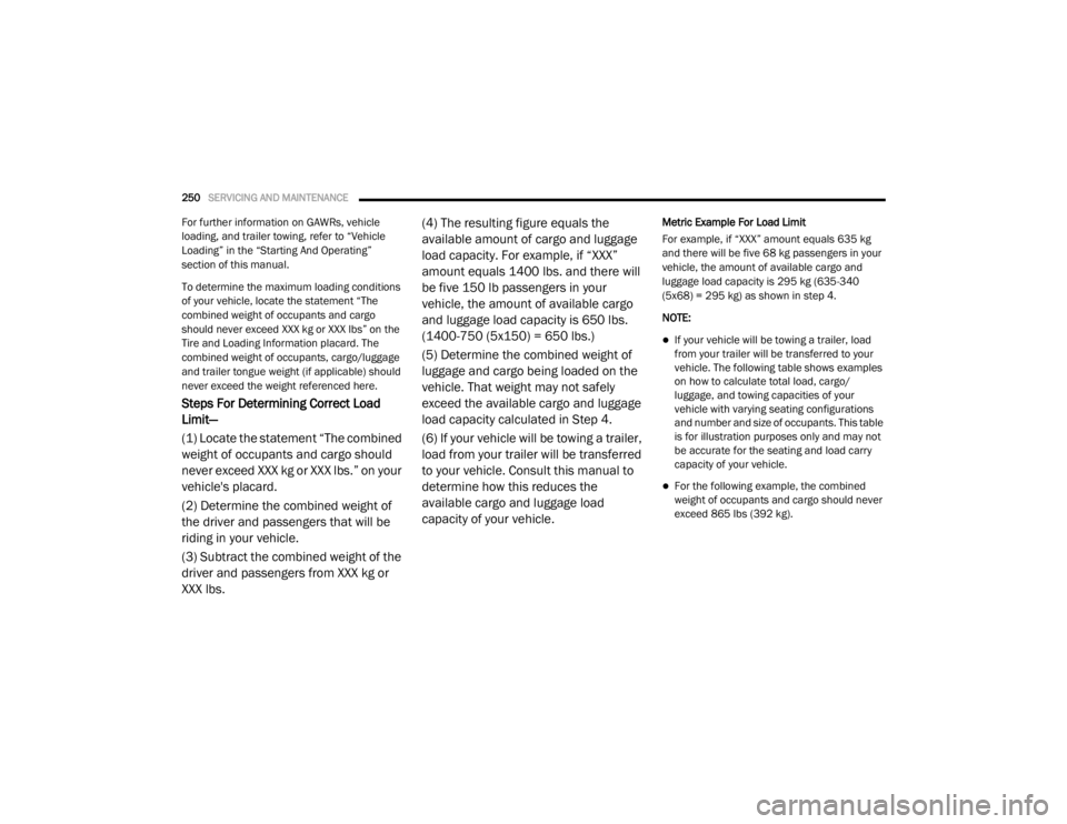
Super Console — If Equipped
For vehicles equipped with the Super Console,
the spare tire winch assembly drive nut is
located beneath the console.
Super Console
1. Pull the lower drawer out from the rear of the floor console to gain clear access to the
tire winch drive nut.
Lower Storage Compartment Location
2. Open the front drawer to expose the storage compartment.
3. Remove the liner from the consoles storage compartment to access the spare tire winch
drive nut.
Removing Liner Winch Drive Nut Location
Base Cargo Center Console — If Equipped
Pull the Winch Cover assembly plug and
retainer clip to access the winch drive nut.
Winch Cover Assembly Plug (If Equipped)
1 — Lower Drawer
2 — Front Drawer/Liner
20_RT_OM_EN_USC_t.book Page 204
Page 212 of 380

210IN CASE OF EMERGENCY
10. Place the deflated (flat) tire and compact
spare tire cover assembly in the rear cargo
area. Do not stow the deflated tire in the
compact spare tire location. Have the
full-sized tire repaired or replaced, as soon
as possible.
11. Stow the cable and wheel spacer before driving the vehicle. Reassemble the winch
handle extensions to form a “T” and fit the
winch T-handle over the drive nut. Rotate
the nut to the right until the winch
mechanism clicks at least three times.
NOTE:
Refer to the “Spare Tire Tools” section for
instructions on assembling the T-handle.
12. Stow the jack, jack handle and winch handle tools back in the stowage
compartment.
13. Check the compact spare tire pressure as soon as possible. Correct the tire pressure,
as required.Securing The Compact Spare Tire
1. Assemble the winch handle extensions to form a T-handle and fit the winch T-handle
over the drive nut. Rotate the nut to the left
until the winch mechanism stops turning
freely. This will allow enough slack in the
cable to allow you to pull the wheel spacer
out from under the vehicle.
2. Assemble the winch handle extensions to form the spare tire hook, and pull the wheel
spacer from under the vehicle. 3. Turn the compact spare tire so that the
valve stem is down, and place the tire into
the compact spare tire/cover assembly.
Slide the wheel spacer through the center of
the wheel and compact spare tire/cover
assembly, so that the two retainer tabs
snap out and engage the compact spare tire
cover on the opposite side.
WARNING!
A loose compact spare tire/cover assembly,
thrown forward in a collision or hard stop
could endanger the occupants of the vehicle.
Always stow the compact spare tire with the
cover assembly in the place provided.
CAUTION!
The winch mechanism is designed for use
with the winch T-handle only. Use of an air
wrench or other power tools is not
recommended and can damage the winch.
WARNING!
Verify that both retainer tabs of the wheel
spacer have been properly extended through
the center of the wheel and compact spare
tire/cover assembly. Failure to properly
engage both retainer tabs could result in loss
of the compact spare tire and cover
assembly, which will cause vehicle damage
and may cause loss of vehicle control and
serious personal injury.
CAUTION!
The compact spare tire/cover assembly must
be used when the compact spare tire is
stored. Failure to use this cover could
drastically reduce the life of the compact
spare tire.
20_RT_OM_EN_USC_t.book Page 210
Page 214 of 380

212IN CASE OF EMERGENCY
6. Finish tightening the lug nuts. Push down on
the wrench while at the end of the handle
for increased leverage. Tighten the lug nuts
in a star pattern until each nut has been
tightened twice. Refer to “Wheel And Tire
Torque Specifications” in “Technical
Specifications” for proper wheel lug nut
torque. If in doubt about the correct
tightness, have them checked with a torque
wrench by an authorized dealer or at a
service station.
7. After 25 miles (40 km) check the lug nut torque with a torque wrench to ensure that
all lug nuts are properly seated against the
wheel.
Vehicles Without Wheel Covers
1. Mount the road tire on the axle.
2. Install the remaining lug nuts with the cone shaped end of the nut toward the wheel.
Lightly tighten all the lug nuts until the
wheel sits flush onto the hub and there is no
play. The nuts will have to be fully tightened
once the vehicle is lowered. Tightening an
improperly seated wheel under vehicle load
can damage the threads, cause vibration,
and undermine safety. 3. Lower the vehicle to the ground by turning
the jack handle counterclockwise.
4. Finish tightening the lug nuts. Push down on the wrench while at the end of the handle
for increased leverage. Tighten the lug nuts
in a star pattern until each nut has been
tightened twice. Refer to “Wheel And Tire
Torque Specifications” in the “Technical
Specifications” section for proper wheel lug
nut torque. If in doubt about the correct
tightness, have them checked with a torque
wrench by an authorized dealer or at a
service station.
5. After 25 miles (40 km) check the lug nut torque with a torque wrench to ensure that
all lug nuts are properly seated against the
wheel.
TIRE SERVICE KIT — IF EQUIPPED
Your vehicle may be equipped with a Tire
Service Kit. Small punctures up to 1/4 inch
(6 mm) in the tire tread can be sealed with Tire
Service Kit. Foreign objects (e.g., screws or
nails) should not be removed from the tire. Tire
Service Kit can be used in outside temperatures
down to approximately -4°F (-20°C). This kit will
provide a temporary tire seal, allowing you to
drive your vehicle up to 100 miles (160 km)
with a maximum speed of 50 mph (80 km/h).
Tire Service Kit Storage
The Tire Service Kit is stowed behind the rear
left side trim panel in the rear cargo area.
Tire Service Kit Location
WARNING!
To avoid the risk of forcing the vehicle off the
jack, do not tighten the wheel nuts fully until
the vehicle has been lowered. Failure to
follow this warning may result in serious
injury.
20_RT_OM_EN_USC_t.book Page 212
Page 252 of 380

250SERVICING AND MAINTENANCE
For further information on GAWRs, vehicle
loading, and trailer towing, refer to “Vehicle
Loading” in the “Starting And Operating”
section of this manual.
To determine the maximum loading conditions
of your vehicle, locate the statement “The
combined weight of occupants and cargo
should never exceed XXX kg or XXX lbs” on the
Tire and Loading Information placard. The
combined weight of occupants, cargo/luggage
and trailer tongue weight (if applicable) should
never exceed the weight referenced here.
Steps For Determining Correct Load
Limit—
(1) Locate the statement “The combined
weight of occupants and cargo should
never exceed XXX kg or XXX lbs.” on your
vehicle's placard.
(2) Determine the combined weight of
the driver and passengers that will be
riding in your vehicle.
(3) Subtract the combined weight of the
driver and passengers from XXX kg or
XXX lbs. (4) The resulting figure equals the
available amount of cargo and luggage
load capacity. For example, if “XXX”
amount equals 1400 lbs. and there will
be five 150 lb passengers in your
vehicle, the amount of available cargo
and luggage load capacity is 650 lbs.
(1400-750 (5x150) = 650 lbs.)
(5) Determine the combined weight of
luggage and cargo being loaded on the
vehicle. That weight may not safely
exceed the available cargo and luggage
load capacity calculated in Step 4.
(6) If your vehicle will be towing a trailer,
load from your trailer will be transferred
to your vehicle. Consult this manual to
determine how this reduces the
available cargo and luggage load
capacity of your vehicle.
Metric Example For Load Limit
For example, if “XXX” amount equals 635 kg
and there will be five 68 kg passengers in your
vehicle, the amount of available cargo and
luggage load capacity is 295 kg (635-340
(5x68) = 295 kg) as shown in step 4.
NOTE:
If your vehicle will be towing a trailer, load
from your trailer will be transferred to your
vehicle. The following table shows examples
on how to calculate total load, cargo/
luggage, and towing capacities of your
vehicle with varying seating configurations
and number and size of occupants. This table
is for illustration purposes only and may not
be accurate for the seating and load carry
capacity of your vehicle.
For the following example, the combined
weight of occupants and cargo should never
exceed 865 lbs (392 kg).
20_RT_OM_EN_USC_t.book Page 250
Page 266 of 380

264SERVICING AND MAINTENANCE
Special Care
If you drive on salted or dusty roads or if you
drive near the ocean, hose off the undercar -
riage at least once a month.
It is important that the drain holes in the
lower edges of the doors, rocker panels, and
trunk be kept clear and open.
If you detect any stone chips or scratches in
the paint, touch them up immediately. The
cost of such repairs is considered the respon -
sibility of the owner.
If your vehicle is damaged due to a collision
or similar cause that destroys the paint and
protective coating, have your vehicle repaired
as soon as possible. The cost of such repairs
is considered the responsibility of the owner.
If you carry special cargo such as chemicals,
fertilizers, de-icer salt, etc., be sure that such
materials are well packaged and sealed.
If a lot of driving is done on gravel roads,
consider mud or stone shields behind each
wheel.
Use Mopar Touch Up Paint on scratches as
soon as possible. An authorized dealer has
touch up paint to match the color of your
vehicle.
INTERIORS
Seats And Fabric Parts
Use Mopar Total Clean to clean fabric
upholstery and carpeting.
Seat Belt Maintenance
Do not bleach, dye or clean the belts with
chemical solvents or abrasive cleaners. This will
weaken the fabric. Sun damage can also
weaken the fabric.
If the belts need cleaning, use a mild soap
solution or lukewarm water. Do not remove the
belts from the vehicle to wash them. Dry with a
soft cloth. Replace the belts if they appear frayed or worn
or if the buckles do not work properly.
Plastic And Coated Parts
Use Mopar Total Clean to clean vinyl upholstery.
WARNING!
Do not use volatile solvents for cleaning
purposes. Many are potentially flammable,
and if used in closed areas they may cause
respiratory harm.
WARNING!
A frayed or torn belt could rip apart in a
collision and leave you with no protection.
Inspect the belt system periodically, checking
for cuts, frays, or loose parts. Damaged parts
must be replaced immediately. Do not
disassemble or modify the system. Seat belt
assemblies must be replaced after a collision
if they have been damaged (i.e., bent
retractor, torn webbing, etc.).
CAUTION!
Direct contact of air fresheners, insect
repellents, suntan lotions, or hand sani
-
tizers to the plastic, painted, or decorated
surfaces of the interior may cause perma -
nent damage. Wipe away immediately.
Damage caused by these type of products
may not be covered by your New Vehicle
Limited Warranty.
20_RT_OM_EN_USC_t.book Page 264
Page 371 of 380

369
Brake System
...................................... 242, 266Anti-Lock (ABS).......................................... 266Fluid Check..................................... 243, 274Parking...................................................... 164Warning Light.............................................. 94Brake/Transmission Interlock....................... 166Bulb Replacement......................................... 194Bulbs, Light.......................................... 161, 194
C
Calibration Compass
..................................................... 89Camera, Rear................................................ 179Capacities, Fluid............................................ 271Caps, FillerOil (Engine)................................................ 231Power Steering.......................................... 173Radiator (Coolant Pressure)...................... 241Car Washes................................................... 263Carbon Monoxide Warning.................. 159, 270CargoVehicle Loading........................................... 63Cargo Area Cover............................................. 63Cargo Compartment........................................ 63Luggage Carrier........................................... 79Cellular Phone..................................... 304, 359Center High Mounted Stop Light...................197Certification Label......................................... 182Chains, Tire.................................................... 260Change Oil Indicator........................................ 87
Changing A Flat Tire............................. 202, 244Chart, Tire Sizing........................................... 246Check Engine Light
(Malfunction Indicator Light)......................... 102Checking Your Vehicle For Safety................. 159Checks, Safety.............................................. 159Child Restraint.............................................. 141Child RestraintsBooster Seats........................................... 144Child Seat Installation..................... 153, 155How To Stow An unused ALR Seat Belt.... 152Infant And Child Restraints....................... 142Locating The LATCH Anchorages.............. 149Lower Anchors And Tethers For Children.. 146Older Children And Child Restraints......... 143Seating Positions...................................... 145Using The Top Tether Anchorage.............. 157Clean Air Gasoline......................................... 268CleaningWheels..................................................... 259Climate Control................................................ 42Automatic.................................................... 48Manual........................................................ 42Coat Hook........................................................ 73Cold Weather Operation............................... 163Compact Spare Tire...................................... 257Compass.......................................................... 88Calibration................................................... 89Variance...................................................... 89Computer, Trip/Travel............................... 87, 93
Console............................................................69Floor............................................................69Console, Overhead...........................................71Contract, Service........................................... 365Cooling Pressure Cap (Radiator Cap)............ 241Cooling System............................................. 239Adding Coolant (Antifreeze)...................... 240Cooling Capacity....................................... 271Disposal Of Used Coolant......................... 242Drain, Flush, And Refill............................. 240Inspection................................................. 240Points To Remember................................ 242Pressure Cap............................................ 241Radiator Cap............................................. 241Selection Of Coolant
(Antifreeze).............................240, 271, 272Corrosion Protection..................................... 262Cruise Light................................................... 100Cupholders............................................. 73, 265Customer Assistance.................................... 364Cybersecurity................................................ 275
D
Daytime Brightness, Interior Lights..................41Daytime Running Lights............................37, 38Dealer Service............................................... 233Defroster, Windshield................................... 160Delay (Intermittent) Wipers..............................42Diagnostic System, Onboard......................... 101
11
20_RT_OM_EN_USC_t.book Page 369