2020 DODGE CHARGER instrument panel
[x] Cancel search: instrument panelPage 192 of 412
190STARTING AND OPERATING
To change between the different control modes,
push the Adaptive Cruise Control (ACC) on/off
button which turns the ACC and the Normal
(Fixed Speed) Cruise Control off. Pushing the
Normal (Fixed Speed) Cruise Control on/off
button will result in turning on (changing to) the
Normal (Fixed Speed) Cruise Control mode.
To Set A Desired Speed
Turn the Normal (Fixed Speed) Cruise
Control on. When the vehicle has
reached the desired speed, push the
SET (+) or SET (-) button and release.
Release the accelerator and the vehicle will
operate at the selected speed. Once a speed
has been set a message “CRUISE CONTROL SET TO MPH (km/h)” will appear indicating what
speed was set. This light will turn on when the
system is turned on via the on/off control. It
turns green when the cruise control is set.
To Vary The Speed Setting
To Increase Speed
When the Normal (Fixed Speed) Cruise Control
is set, you can increase speed by pushing the
SET
(+) button.
The driver's preferred units can be selected
through the instrument cluster display. Refer to
“Getting To Know Your Instrument Panel” for
more information. The speed increment shown
is dependent on the speed of U.S. (mph) or
Metric (km/h) units:
U.S. Speed (mph)
Pushing the SET (+) button once will result in
a 1 mph increase in set speed. Each subse -
quent tap of the button results in an increase
of 1 mph.
If the button is continually pushed, the set
speed will continue to increase in 5 mph
increments until the button is released. The
increase in set speed is reflected in the
instrument cluster display. Metric Speed (km/h)
Pushing the SET (+) button once will result in
a 1 km/h increase in set speed. Each subse -
quent tap of the button results in an increase
of 1 km/h.
If the button is continually pushed, the set
speed will continue to increase in 10 km/h
increments until the button is released. The
increase in set speed is reflected in the
instrument cluster display.
To Decrease Speed
When the Normal (Fixed Speed) Cruise Control
is set, you can decrease speed by pushing the
SET (-) button.
The driver's preferred units can be selected
through the instrument cluster display. Refer to
“Getting To Know Your Instrument Panel” for
more information. The speed decrement shown
is dependent on the speed of U.S. (mph) or
Metric (km/h) units:
U.S. Speed (mph)
Pushing the SET (-) button once will result in
a 1 mph decrease in set speed. Each subse -
quent tap of the button results in a decrease
of 1 mph.
WARNING!
In the Normal (Fixed Speed) Cruise Control mode,
the system will not react to vehicles ahead. In
addition, the proximity warning does not activate
and no alarm will sound even if you are too close
to the vehicle ahead since neither the presence
of the vehicle ahead nor the vehicle-to-vehicle
distance is detected. Be sure to maintain a safe
distance between your vehicle and the vehicle
ahead. Always be aware which mode is selected.
20_LD_OM_EN_USC_t.book Page 190
Page 194 of 412

192STARTING AND OPERATING
PARKSENSE SENSORS
The four ParkSense sensors, located in the rear
fascia/bumper, monitor the area behind the
vehicle that is within the sensors’ field of view.
The sensors can detect obstacles from
approximately 12 inches (30 cm) up to
79 inches (200 cm) from the rear fascia/
bumper in the horizontal direction, depending
on the location, type and orientation of the
obstacle.
PARKSENSE WARNING DISPLAY
The ParkSense Warning screen will only be
displayed if “Sound and Display” is selected
from the Customer - Programmable Features
section of the Uconnect system. Refer to
"Uconnect Settings” in “Multimedia” for further
information. The ParkSense Warning screen is located within
the instrument cluster display. It provides visual
warnings to indicate the distance between the
rear fascia/bumper and the detected obstacle.
Refer to “Instrument Cluster Display” in
“Getting To Know Your Instrument Panel” for
further information.
PARKSENSE DISPLAY
When the vehicle is in REVERSE, the warning
display will turn on indicating the system status.
The system will indicate a detected obstacle by
showing a single arc in one or more regions
based on the obstacle’s distance and location
relative to the vehicle.
If an obstacle is detected in the center rear
region, the display will show a single solid arc in
the center rear region and will produce a one-half
second tone. As the vehicle moves closer to the
obstacle, the display will show the single arc
moving closer to the vehicle and the sound tone
will change from slow, to fast, to continuous.
If an obstacle is detected in the left and/or right
rear region, the display will show a single
flashing arc in the left and/or right rear region
and will produce a fast sound tone. As the
vehicle moves closer to the obstacle, the
display will show the single arc moving closer to
the vehicle and the sound tone will change from
fast to continuous.
20_LD_OM_EN_USC_t.book Page 192
Page 196 of 412
194STARTING AND OPERATING
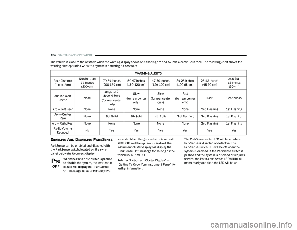
The vehicle is close to the obstacle when the warning display shows one flashing arc and sounds a continuous tone. The following chart shows the
warning alert operation when the system is detecting an obstacle:
ENABLING AND DISABLING PARKSENSE
ParkSense can be enabled and disabled with
the ParkSense switch, located on the switch
panel below the Uconnect display.
When the ParkSense switch is pushed
to disable the system, the instrument
cluster will display the “ParkSense
Off” message for approximately five seconds. When the gear selector is moved to
REVERSE and the system is disabled, the
instrument cluster display will display the
“ParkSense Off” message for as long as the
vehicle is in REVERSE.
Refer to “Instrument Cluster Display” in
“Getting To Know Your Instrument Panel” for
further information.
The ParkSense switch LED will be on when
ParkSense is disabled or defective. The
ParkSense switch LED will be off when the
system is enabled. If the ParkSense switch is
pushed and the system is disabled or requires
service, the ParkSense switch LED will blink
momentarily and then the LED will be on.
WARNING ALERTS
Rear Distance
(inches/cm) Greater than
79 inches (200 cm) 79-59 inches
(200-150 cm) 59-47 inches
(150-120 cm) 47-39 inches
(120-100 cm) 39-25 inches
(100-65 cm) 25-12 inches
(65-30 cm) Less than
12 inches (30 cm)
Audible Alert Chime NoneSingle 1/2-
Second Tone
(for rear center only) Slow
(for rear center only) Slow
(for rear center only) Fast
(for rear center only) Fast Continuous
Arc — Left Rear None NoneNoneNoneNone 2nd Flashing 1st Flashing
Arc — Center Rear None 6th Solid 5th Solid 4th Solid 3rd Flashing 2nd Flashing 1st Flashing
Arc — Right Rear None NoneNoneNoneNone 2nd Flashing 1st Flashing
Radio Volume Reduced No
Yes YesYesYesYesYes
20_LD_OM_EN_USC_t.book Page 194
Page 197 of 412

STARTING AND OPERATING195
SERVICE THE PARKSENSE REAR PARK
A
SSIST SYSTEM
During vehicle start up, when the ParkSense
Rear Park Assist System has detected a faulted
condition, the instrument cluster display will
actuate a single chime, once per ignition cycle,
and it will display the “PARKSENSE
UNAVAILABLE WIPE REAR SENSORS” or the
“PARKSENSE UNAVAILABLE SERVICE
REQUIRED” message. Refer to “Instrument
Cluster Display” in “Getting To Know Your
Instrument Panel” for further information.
When the gear selector is moved to REVERSE
and the system has detected a faulted
condition, the instrument cluster display will
show the "PARKSENSE UNAVAILABLE WIPE
REAR SENSORS" or "PARKSENSE UNAVAILABLE
SERVICE REQUIRED" message for as long as the
vehicle is in REVERSE. Under this condition,
ParkSense will not operate.
If “PARKSENSE UNAVAILABLE WIPE REAR
SENSORS” appears in the instrument cluster
display, make sure the outer surface and the
underside of the rear fascia/bumper is clean
and clear of snow, ice, mud, dirt or other
obstruction and then cycle the ignition. If the message continues to appear, see an
authorized dealer.
If “PARKSENSE UNAVAILABLE SERVICE
REQUIRED” appears in the instrument cluster
display, see an authorized dealer.
CLEANING THE PARKSENSE SYSTEM
Clean the Rear Park Assist sensors with water,
car wash soap and a soft cloth. Do not use
rough or hard cloths. In washing stations, clean
sensors quickly keeping the vapor jet/high
pressure washing nozzles at least 4 inches
(10 cm) from the sensors. Do not scratch or
poke the sensors. Otherwise, you could
damage the sensors.
PARKSENSE SYSTEM USAGE
P
RECAUTIONS
NOTE:
Ensure that the rear bumper is free of snow, ice,
mud, dirt and debris to keep the ParkSense
system operating properly.
Jackhammers, large trucks, and other vibrations
could affect the performance of ParkSense or
render the system temporarily unavailable.
When you turn ParkSense off in DRIVE, the
instrument cluster will display "PARKSENSE
OFF" for five seconds. Furthermore, once you
turn ParkSense off, it remains off until you
turn it on again, even if you cycle the ignition.
When you move the gear selector to the
REVERSE position and ParkSense is turned
off, the instrument cluster display will show
the “PARKSENSE OFF” message for as long
as the vehicle is in REVERSE.
ParkSense will reduce the volume of the
radio when it is sounding an audio tone.
Clean the ParkSense sensors regularly,
taking care not to scratch or damage them.
The sensors must not be covered with ice,
snow, slush, mud, dirt or debris. Failure to do
so can result in the system not working prop -
erly. The ParkSense system might not detect
an obstacle behind the fascia/bumper, or it
could provide a false indication that an
obstacle is behind the fascia/bumper.
Ensure the ParkSense system is off if objects
such as bicycle carriers, trailer hitches, etc.,
are placed within 12 inches (30 cm) from the
rear fascia/bumper. Failure to do so can
result in the system misinterpreting a close
5
20_LD_OM_EN_USC_t.book Page 195
Page 217 of 412
IN CASE OF EMERGENCY215
Even if the SOS Call system is fully functional,
factors beyond FCA US LLC’s control may
prevent or stop the SOS Call system operation.
These include, but are not limited to, the
following factors:
The ignition is in the OFF position.
The vehicle’s electrical systems are not
intact.
The SOS Call system software and/or hard -
ware are damaged during a crash.
The vehicle battery loses power or becomes
disconnected during a vehicle crash.
LTE (voice/data) or 4G (data) network and/or
Global Positioning Satellite signals are
unavailable or obstructed.
Equipment malfunction at the SOS operator
facility.
Operator error by the SOS operator.
LTE (voice/data) or 4G (data) network
congestion.
Weather.
Buildings, structures, geographic terrain, or
tunnels. NOTE:
Your vehicle may be transmitting data as
authorized by the subscriber.
Never place anything on or near the vehicle’s
LTE (voice/data) or 4G (data) and GPS
antennas. You could prevent LTE (voice/
data) or 4G (data) and GPS signal reception,
which can prevent your vehicle from placing
an emergency call. An operable LTE (voice/
data) or 4G (data) network connection and a
GPS signal is required for the SOS Call
system to function properly.
WARNING!
Ignoring the Rearview Mirror light could
mean you will not have SOS Call services. If
the Rearview Mirror light is illuminated,
have an authorized dealer service the SOS
Call system immediately.
The Occupant Restraint Control module
turns on the air bag Warning Light on the
instrument panel if a malfunction in any
part of the system is detected. If the Air Bag
Warning Light is illuminated, have an
authorized dealer service the Occupant
Restraint Control system immediately.
WARNING!
ALWAYS obey traffic laws and pay attention to
the road. ALWAYS drive safely with your hands
on the steering wheel. You have full
responsibility and assume all risks related to
the use of the Uconnect and SiriusXM
Guardian™ features and applications in this
vehicle. Only use Uconnect features and
SiriusXM Guardian™ services when it is safe
to do so. Failure to do so may result in an
accident involving serious injury or death.
6
20_LD_OM_EN_USC_t.book Page 215
Page 240 of 412
238IN CASE OF EMERGENCY
3. The Sealant Bottle (1) may be empty due to
previous use. Call for assistance.
NOTE:
If the Mode Select Knob (5) is on Air Mode and
the pump is operating, air will dispense from the
Air Pump Hose (7) only, not the Sealant Hose
(6).
If the sealant (white fluid) does flow through the
Sealant Hose (6):
1. Continue to operate the pump until sealant is no longer flowing through the hose
(typically takes 30 - 70 seconds). As the
sealant flows through the Sealant Hose (6),
the Pressure Gauge (3) can read as high as
70 psi (4.8 Bar). The Pressure Gauge (3)
will decrease quickly from approximately
70 psi (4.8 Bar) to the actual tire pressure
when the Sealant Bottle (1) is empty.
2. The pump will start to inject air into the tire immediately after the Sealant Bottle (1) is
empty. Continue to operate the pump and
inflate the tire to the pressure indicated on
the tire pressure label on the driver-side
latch pillar (recommended pressure). Check
the tire pressure by looking at the Pressure
Gauge (3). If the tire does not inflate to at least 26 psi (1.8
Bar) pressure within 15 minutes:
The tire is too badly damaged. Do not attempt
to drive the vehicle further. Call for assis
-
tance.
NOTE:
If the tire becomes overinflated, push the Defla-
tion Button (2) to reduce the tire pressure to the
recommended inflation pressure before
continuing.
If the tire inflates to the recommended pressure
or is at least 26 psi (1.8 Bar) pressure within
15 minutes:
1. Push the Power Button (4) to turn off the Tire Service Kit.
2. Remove the Speed Limit sticker from the top of the Sealant Bottle (1) and place the
sticker on the instrument panel.
3. Immediately disconnect the Sealant Hose (6) from the valve stem, reinstall the cap on
the fitting at the end of the hose, and place
the Tire Service Kit in the vehicle storage
location. Quickly proceed to (D) “Drive
Vehicle.”
(D) Drive Vehicle:
Immediately after injecting sealant and inflating
the tire, drive the vehicle 5 miles (8 km) or
10 minutes to ensure distribution of the Tire
Service Kit Sealant within the tire. Do not
exceed 50 mph (80 km/h).
CAUTION!
The metal end fitting from Power Plug (8)
may get hot after use, so it should be
handled carefully.
Failure to reinstall the cap on the fitting at the
end of the Sealant Hose (6) can result in
sealant contacting your skin, clothing, and the
vehicle’s interior. It can also result in sealant
contacting internal Tire Service Kit components
which may cause permanent damage to the kit.
WARNING!
Tire Service Kit is not a permanent flat tire repair.
Have the tire inspected and repaired or replaced
after using Tire Service Kit. Do not exceed
50 mph (80 km/h) until the tire is repaired or
replaced. Failure to follow this warning can result
in injuries that are serious or fatal to you, your
passengers, and others around you.
20_LD_OM_EN_USC_t.book Page 238
Page 241 of 412

IN CASE OF EMERGENCY239
(E) After Driving:
Pull over to a safe location. Refer to “(A)
Whenever You Stop To Use Tire Service Kit”
before continuing.
1. Push in the Mode Select Knob (5) and turn
to the Air Mode position.
2. Uncoil the power plug and insert the plug into the vehicle's 12 Volt power outlet.
3. Uncoil the Air Pump Hose (7) (black in color) and screw the fitting at the end of hose (7)
onto the valve stem.
4. Check the pressure in the tire by reading the Pressure Gauge (3).
If tire pressure is less than 19 psi (1.3 Bar):
The tire is too badly damaged. Do not attempt to
drive the vehicle further. Call for assistance.
If the tire pressure is 19 psi (1.3 Bar) or higher:
1. Push the Power Button (4) to turn on Tire Service Kit and inflate the tire to the
pressure indicated on the tire and loading
information label on the driver-side door
opening.
NOTE:
If the tire becomes over-inflated, push the
Deflation Button (2) to reduce the tire pressure
to the recommended inflation pressure before
continuing.
2. Disconnect the Tire Service Kit from the
valve stem, reinstall the cap on the valve
stem and unplug from 12 Volt outlet.
3. Place the Tire Service Kit in its proper storage area in the vehicle.
4. Have the tire inspected and repaired or replaced at the earliest opportunity at an
authorized dealer or tire service center.
5. Remove the Speed Limit sticker from the instrument panel after the tire has been
repaired.
6. Replace the Sealant Bottle (1) and Sealant Hose (6) assembly at an authorized dealer
as soon as possible. Refer to “(F) Sealant
Bottle And Hose Replacement”.
NOTE:
When having the tire serviced, advise the autho -
rized dealer or service center that the tire has
been sealed using the Tire Service Kit.
(F) Sealant Bottle And Hose Replacement:
1. Uncoil the Sealant Hose (6) (clear in color).
2. Locate the round Sealant Bottle release button in the recessed area under the
sealant bottle.
3. Push the Sealant Bottle release button. The Sealant Bottle (1) will pop up. Remove the
bottle and dispose of it accordingly.
4. Clean any remaining sealant from the Tire Service Kit housing.
5. Position the new Sealant Bottle (1) in the housing so that the Sealant Hose (6) aligns
with the hose slot in the front of the
housing. Push the bottle into the housing.
An audible click will be heard indicating the
bottle is locked into place.
6. Verify that the cap is installed on the fitting at the end of the Sealant Hose (6) and
return the hose to its storage area (located
on the bottom of the air pump).
7. Return the Tire Service Kit to its storage location in the vehicle.
6
20_LD_OM_EN_USC_t.book Page 239
Page 252 of 412
250
SERVICING AND MAINTENANCE
SCHEDULED SERVICING
3.6L AND 5.7L ENGINES
These vehicles are equipped with an automatic
oil change indicator system. The oil change
indicator system will remind you that it is time to
take your vehicle in for scheduled maintenance.
Based on engine operation conditions, the oil
change indicator message will illuminate. This
means that service is required for your vehicle.
Operating conditions such as frequent
short-trips, trailer tow, and extremely hot or cold
ambient temperatures will influence when the
“Change Oil” or “Oil Change Required” message
is displayed. Severe Operating Conditions can
cause the change oil message to illuminate as
early as 3,500 miles (5,600 km) since last
reset. Have your vehicle serviced as soon as
possible, within the next 500 miles (805 km).
The “Oil Change Required” message will be
displayed in the instrument cluster and a single
chime will sound, indicating that an oil change
is necessary.An authorized dealer will reset the oil change
indicator message after completing the
scheduled oil change. If a scheduled oil change
is performed by someone other than an
authorized dealer, the message can be reset by
referring to “Instrument Cluster Display” in
“Getting To Know Your Instrument Panel” for
further information.
NOTE:
Under no circumstances should oil change
intervals exceed 10,000 miles (16,000 km),
12 months or 350 hours of engine run time,
whichever comes first. The 350 hours of engine
run or idle time is generally only a concern for
fleet customers.
Severe Duty All Models
Change Engine Oil at 4,000 miles (6,500 km) or
350 hours of engine run time if the vehicle is
operated in a dusty and off-road environment,
or is operated predominantly at idle or only very
low engine RPM. This type of vehicle use is
considered Severe Duty.
Once A Month Or Before A Long Trip:
Check engine oil level.
Check windshield washer fluid level.
Check tire pressure and look for unusual
wear or damage. Rotate tires at the first sign
of irregular wear, even if it occurs before your
next scheduled service.
Check the fluid levels of the coolant reservoir,
brake master cylinder, and power steering
(if equipped) and fill as needed.
Check function of all interior and exterior
lights.
Maintenance Plan — 3.6L And 5.7L
Required Maintenance Intervals:
Refer to the maintenance schedules on the
following page for the required maintenance
intervals. More frequent maintenance may be
needed in severe conditions, such as dusty
areas and very short trip driving. In some
extreme conditions, additional maintenance
not specified in the maintenance schedule may
be required.
20_LD_OM_EN_USC_t.book Page 250