2020 DODGE CHARGER wheel
[x] Cancel search: wheelPage 181 of 412
STARTING AND OPERATING179
ADAPTIVE CRUISE CONTROL (ACC)
O
PERATION
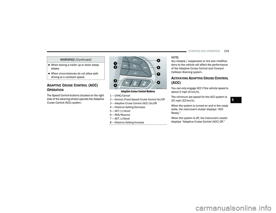
The Speed Control buttons (located on the right
side of the steering wheel) operate the Adaptive
Cruise Control (ACC) system.
Adaptive Cruise Control Buttons
NOTE:
Any chassis / suspension or tire size modifica
-
tions to the vehicle will affect the performance
of the Adaptive Cruise Control and Forward
Collision Warning system.
ACTIVATING ADAPTIVE CRUISE CONTROL
(ACC)
You can only engage ACC if the vehicle speed is
above 0 mph (0 km/h).
The minimum set speed for the ACC system is
20 mph (32 km/h).
When the system is turned on and in the ready
state, the instrument cluster displays “ACC
Ready.”
When the system is off, the instrument cluster
displays “Adaptive Cruise Control (ACC) Off.”
When towing a trailer up or down steep
slopes.
When circumstances do not allow safe
driving at a constant speed.
WARNING! (Continued)
1 — CANC/Cancel
2 — Normal (Fixed Speed) Cruise Control On/Off
3 — Adaptive Cruise Control (ACC) On/Off
4 — Distance Setting Decrease
5 — SET (+)/Accel
6 — RES/Resume
7 — SET (-)/Decel
8 — Distance Setting Increase
5
20_LD_OM_EN_USC_t.book Page 179
Page 187 of 412

STARTING AND OPERATING185
ADAPTIVE CRUISE CONTROL (ACC)
M
ENU
The instrument cluster display will show the
current ACC system settings. The instrument
cluster display is located in the center of the
instrument cluster. The information it displays
depends on ACC system status.
Push the Adaptive Cruise Control (ACC) on/off
button (located on the steering wheel) until one
of the following appears in the instrument
cluster display:
Adaptive Cruise Control Off
When ACC is deactivated, the display will read
“Adaptive Cruise Control Off.”
Adaptive Cruise Control Ready
When ACC is activated, but the vehicle speed
setting has not been selected, the display will
read “Adaptive Cruise Control Ready.”
Adaptive Cruise Control Set
When the SET (+) or the SET (-) button (located
on the steering wheel) is pushed, the display will
read “ACC SET.” When ACC is set, the set speed will show in the
instrument cluster display.
The ACC screen may display once again if any
ACC activity occurs, which may include any of
the following:
System Cancel
Driver Override
System Off
ACC Proximity Warning
ACC Unavailable Warning
The instrument cluster display will return to
the last display selected after five seconds of
no ACC display activity
DISPLAY WARNINGS AND
M
AINTENANCE
“Wipe Front Radar Sensor In Front Of
Vehicle” Warning
The “ACC/FCW Unavailable Wipe Front Radar
Sensor” warning will display and also a chime
will indicate when conditions temporarily limit
system performance. This most often occurs at times of poor visibility,
such as in snow or heavy rain. The ACC system
may also become temporarily blinded due to
obstructions, such as mud, dirt or ice. In these
cases, the instrument cluster display will display
“ACC/FCW Unavailable Wipe Front Radar
Sensor” and the system will deactivate.
The “ACC/FCW Unavailable Wipe Front Radar
Sensor” message can sometimes be displayed
while driving in highly reflective areas (i.e.
tunnels with reflective tiles, or ice and snow).
The ACC system will recover after the vehicle
has left these areas. Under rare conditions,
when the radar is not tracking any vehicles or
objects in its path this warning may temporarily
occur.
NOTE:
If the “ACC/FCW Unavailable Wipe Front Radar
Sensor” warning is active Normal (Fixed Speed)
Cruise Control is still available. For additional
information refer to “Normal (Fixed Speed)
Cruise Control Mode” in this section.
If weather conditions are not a factor, the driver
should examine the sensor. It may require
cleaning or removal of an obstruction. The
sensor is located in the center of the vehicle
behind the lower grille.
5
20_LD_OM_EN_USC_t.book Page 185
Page 198 of 412

196STARTING AND OPERATING
(Continued)
object as a sensor problem, causing the
“PARKSENSE UNAVAILABLE SERVICE
REQUIRED” message to be shown in the
instrument cluster display.
LANESENSE — IF EQUIPPED
LANESENSE OPERATION
The LaneSense system is operational at speeds
above 37 mph (60 km/h) and below 112 mph
(180 km/h). The LaneSense system uses a
forward looking camera to detect lane markings
and measure vehicle position within the lane
boundaries.
When both lane markings are detected and the
driver unintentionally drifts out of the lane (no
turn signal applied), the LaneSense system
provides a haptic warning in the form of torque
applied to the steering wheel to prompt the
driver to remain within the lane boundaries. If
the driver continues to unintentionally drift out
of the lane, the LaneSense system provides a
visual warning through the instrument cluster
display to prompt the driver to remain within the
lane boundaries. The driver may manually override the haptic
warning by applying torque into the steering
wheel at any time.
When only a single lane marking is detected
and the driver unintentionally drifts across the
lane marking (no turn signal applied), the
LaneSense system provides visual warnings
through the instrument cluster display to
prompt the driver to remain within the lane.
When only a single lane marking is detected, a
haptic (torque) warning will not be provided.
NOTE:
When operating conditions have been met, the
LaneSense system will monitor if the driver’s
hands are on the steering wheel and provides
an audible warning to the driver when the
driver’s hands are not detected on the steering
wheel. The system will cancel if the driver does
not return their hands to the wheel.
TURNING LANESENSE ON OR OFF
The default status of LaneSense is off.
The LaneSense button is located on the center
stack below the Uconnect display.
WARNING!
Drivers must be careful when backing up
even when using the Rear Park Assist system.
Always check carefully behind your vehicle,
and be sure to check for pedestrians,
animals, other vehicles, obstructions, or blind
spots before backing up. You are responsible
for the safety of your surroundings and must
continue to pay attention while backing up.
Failure to do so can result in serious injury or
death.
CAUTION!
ParkSense is only a parking aid and it is
unable to recognize every obstacle,
including small obstacles. Parking curbs
might be temporarily detected or not
detected at all. Obstacles located above or
below the sensors will not be detected
when they are in close proximity.
The vehicle must be driven slowly when
using ParkSense in order to be able to stop
in time when an obstacle is detected. It is
recommended that the driver looks over
his/her shoulder when using ParkSense.
CAUTION!
(Continued)
20_LD_OM_EN_USC_t.book Page 196
Page 199 of 412
STARTING AND OPERATING197
To turn the LaneSense system on,
push the LaneSense button (LED
turns off). A “LaneSense On”
message is shown in the instrument
cluster display.
To turn the LaneSense system off, push the
LaneSense button once (LED turns on).
NOTE:
The LaneSense system will retain the last
system state, on or off, from the last ignition
cycle when the ignition is changed to the ON/
RUN position.
LANESENSE WARNING MESSAGE
The LaneSense system will indicate the current
lane drift condition through the instrument
cluster display.
Premium Instrument Cluster Display Screen —
If Equipped
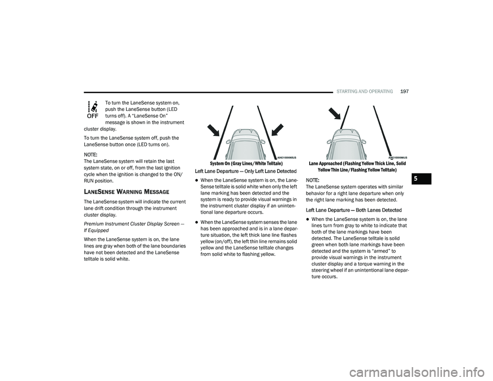
When the LaneSense system is on, the lane
lines are gray when both of the lane boundaries
have not been detected and the LaneSense
telltale is solid white.
System On (Gray Lines/White Telltale)
Left Lane Departure — Only Left Lane Detected
When the LaneSense system is on, the Lane-
Sense telltale is solid white when only the left
lane marking has been detected and the
system is ready to provide visual warnings in
the instrument cluster display if an uninten -
tional lane departure occurs.
When the LaneSense system senses the lane
has been approached and is in a lane depar -
ture situation, the left thick lane line flashes
yellow (on/off), the left thin line remains solid
yellow and the LaneSense telltale changes
from solid white to flashing yellow.
Lane Approached (Flashing Yellow Thick Line, Solid
Yellow Thin Line/Flashing Yellow Telltale)
NOTE:
The LaneSense system operates with similar
behavior for a right lane departure when only
the right lane marking has been detected.
Left Lane Departure — Both Lanes Detected When the LaneSense system is on, the lane
lines turn from gray to white to indicate that
both of the lane markings have been
detected. The LaneSense telltale is solid
green when both lane markings have been
detected and the system is “armed” to
provide visual warnings in the instrument
cluster display and a torque warning in the
steering wheel if an unintentional lane depar -
ture occurs.
5
20_LD_OM_EN_USC_t.book Page 197
Page 200 of 412
198STARTING AND OPERATING
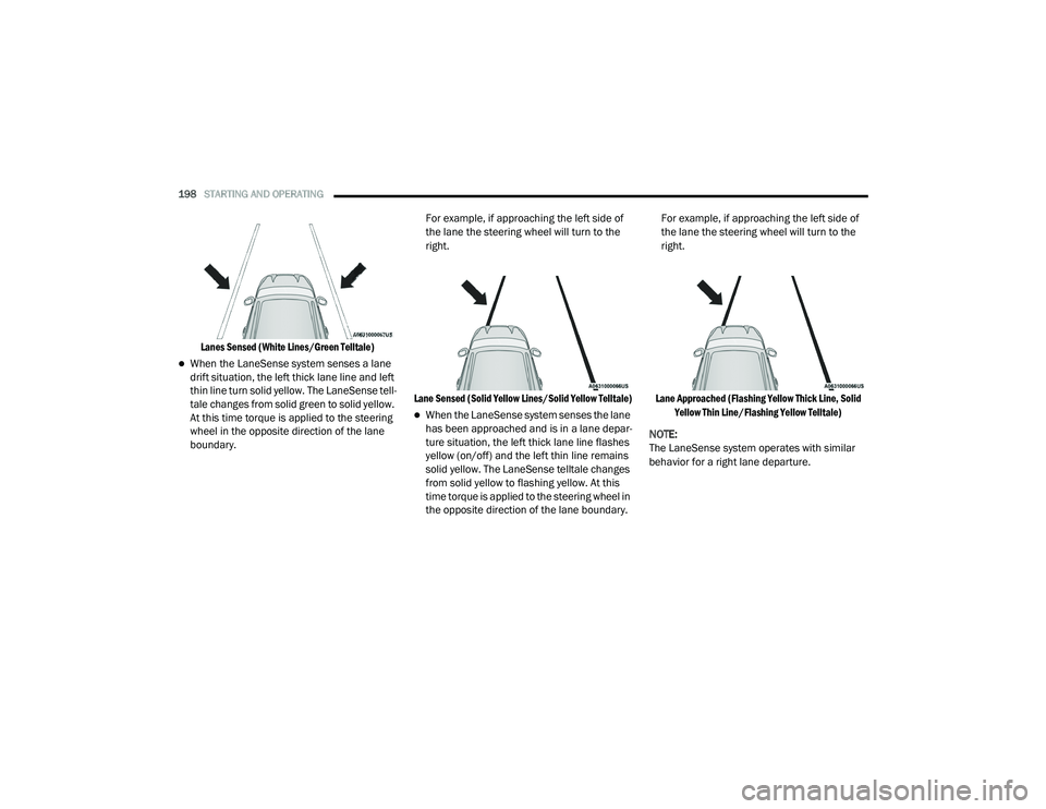
Lanes Sensed (White Lines/Green Telltale)
When the LaneSense system senses a lane
drift situation, the left thick lane line and left
thin line turn solid yellow. The LaneSense tell -
tale changes from solid green to solid yellow.
At this time torque is applied to the steering
wheel in the opposite direction of the lane
boundary. For example, if approaching the left side of
the lane the steering wheel will turn to the
right.
Lane Sensed (Solid Yellow Lines/Solid Yellow Telltale)
When the LaneSense system senses the lane
has been approached and is in a lane depar -
ture situation, the left thick lane line flashes
yellow (on/off) and the left thin line remains
solid yellow. The LaneSense telltale changes
from solid yellow to flashing yellow. At this
time torque is applied to the steering wheel in
the opposite direction of the lane boundary. For example, if approaching the left side of
the lane the steering wheel will turn to the
right.
Lane Approached (Flashing Yellow Thick Line, Solid Yellow Thin Line/Flashing Yellow Telltale)
NOTE:
The LaneSense system operates with similar
behavior for a right lane departure.
20_LD_OM_EN_USC_t.book Page 198
Page 201 of 412
STARTING AND OPERATING199
CHANGING LANESENSE STATUS
The LaneSense system settings can be
configured through the Uconnect system
screen.
Follow these steps to change the LaneSense
settings:
1. Press the “Controls” button located on the
bottom of the Uconnect touchscreen
display.
2. Press the “Settings” button.
3. Press the “Safety & Driving Assistance” button.
When in the Safety & Driving Assistance screen,
you can configure the intensity of the torque
warning and the warning zone sensitivity (early/
late) through the personalization settings.
NOTE:
When enabled the system operates above
37 mph (60 km/h) and below 112 mph (180 km/h).
Use of the turn signal suppresses the warn -
ings.
The system will not apply torque to the
steering wheel whenever a safety system
engages. (Anti-Lock Brakes, Traction Control
System, Electronic Stability Control, Forward
Collision Warning, etc.)
PARKVIEW REAR BACK UP CAMERA
Your vehicle is equipped with the ParkView Rear
Back Up Camera that allows you to see an
on-screen image of the rear surroundings of
your vehicle whenever the gear selector is put
into REVERSE. The ParkView camera is located
on the rear of the vehicle above the rear license
plate. The image will be displayed in the
touchscreen display along with a caution note
to “Check Entire Surroundings” across the top
of the screen. After five seconds, this note will
disappear.
NOTE:
The ParkView Rear Back Up Camera has
programmable modes of operation that may be
selected through the Uconnect system. Refer to
“Uconnect Settings” in “Multimedia” for further
information. If your vehicle is equipped with the Camera
Delay feature and it is turned on, the rear
camera image will be displayed for up to 10
seconds when the vehicle is shifted out of
REVERSE. However, this feature is canceled if
the forward vehicle speed exceeds 8 mph
(13 km/h), the transmission is shifted into
PARK, the vehicle's ignition is placed in the OFF
position, or by pressing the image defeat “X”
button.
If your vehicle is not equipped with the Camera
Delay feature, or it is turned off, when the
vehicle is shifted out of REVERSE the rear
camera mode is exited and the previous
touchscreen display appears again.
When enabled, active guidelines are overlaid on
the image to illustrate the width of the vehicle
and its projected backup path based on the
steering wheel position. The active guidelines
will show separate zones that will help indicate
the distance to the rear of the vehicle.
5
20_LD_OM_EN_USC_t.book Page 199
Page 204 of 412

202STARTING AND OPERATING
VEHICLE LOADING
The load carrying capacity of your vehicle is
shown on the “Vehicle Certification Label”. This
information should be used for passenger and
luggage loading as indicated.
Do not exceed the specified Gross Vehicle
Weight Rating (GVWR) or the Gross Axle Weight
Rating (GAWR).
VEHICLE CERTIFICATION LABEL
Your vehicle has a Vehicle Certification Label
affixed to the drivers side B-pillar or the rear of
the driver’s door.
The label contains the following information:
Name of manufacturer
Month and year of manufacture
Gross Vehicle Weight Rating (GVWR)
Gross Axle Weight Rating (GAWR) front
Gross Axle Weight Rating (GAWR) rear
Vehicle Identification Number (VIN)
Type of vehicle
Month, Day, and Hour of manufacture (MDH)
The bar code allows a computer scanner to read
the VIN.
GROSS VEHICLE WEIGHT RATING
(GVWR)
The GVWR is the total allowable weight of your
vehicle. This includes driver, passengers, and
cargo. The total load must be limited so that you
do not exceed the GVWR.
GROSS AXLE WEIGHT RATING (GAWR)
The GAWR is the maximum capacity of the front
and rear axles. Distribute the load over the front
and rear axles evenly. Make sure that you do
not exceed either front or rear GAWR.
OVERLOADING
The load carrying components (axle, springs,
tires, wheels, etc.) of your vehicle will provide
satisfactory service as long as you do not
exceed the GVWR and the front and rear GAWR.
The best way to figure out the total weight of
your vehicle is to weigh it when it is fully loaded
and ready for operation. Weigh it on a
commercial scale to ensure that it is not over
the GVWR.
Figure out the weight on the front and rear of
the vehicle separately. It is important that you
distribute the load evenly over the front and rear
axles.
CAUTION!
To avoid fuel spillage and overfilling, do not
“top off” the fuel tank after filling.
WARNING!
Because the front wheels steer the vehicle, it
is important that you do not exceed the
maximum front or rear GAWR. A dangerous
driving condition can result if either rating is
exceeded. You could lose control of the
vehicle and have a collision.
20_LD_OM_EN_USC_t.book Page 202
Page 206 of 412
204STARTING AND OPERATING
Tongue Weight (TW)
The tongue weight is the downward force
exerted on the hitch ball by the trailer. You must
consider this as part of the load on your vehicle.
Trailer Frontal Area
The frontal area is the maximum height multiplied
by the maximum width of the front of a trailer.
Trailer Sway Control
The Trailer Sway Control (TSC) can be a
mechanical telescoping link that can be
installed between the hitch receiver and the
trailer tongue that typically provides adjustable
friction associated with the telescoping motion
to dampen any unwanted trailer swaying
motions while traveling. If equipped, the electronic TSC recognizes a
swaying trailer and automatically applies
individual wheel brakes and/or reduces engine
power to attempt to eliminate the trailer sway.
Weight-Carrying Hitch
A weight-carrying hitch supports the trailer
tongue weight, just as if it were luggage located
at a hitch ball or some other connecting point of
the vehicle. These kinds of hitches are the most
popular on the market today and they are
commonly used to tow small and medium sized
trailers.
Weight-Distributing Hitch
A weight-distributing system works by applying
leverage through spring (load) bars. They are
typically used for heavier loads to distribute
trailer tongue weight to the tow vehicle's front
axle and the trailer axle(s). When used in
accordance with the manufacturer's directions,
it provides for a more level ride, offering more
consistent steering and brake control thereby
enhancing towing safety. The addition of a
friction/hydraulic sway control also dampens
sway caused by traffic and crosswinds and
contributes positively to tow vehicle and trailer
stability. Trailer sway control and a weight
distributing (load equalizing) hitch are
recommended for heavier Tongue Weights (TW)
and may be required depending on vehicle and
trailer configuration/loading to comply with
Gross Axle Weight Rating (GAWR) requirements.
WARNING!
It is important that you do not exceed the
maximum front or rear GAWR. A dangerous
driving condition can result if either rating is
exceeded. You could lose control of the
vehicle and have a collision.
WARNING!
An improperly adjusted Weight Distributing
Hitch system may reduce handling,
stability, braking performance, and could
result in a collision.
Weight Distributing Systems may not be
compatible with Surge Brake Couplers.
Consult with your hitch and trailer manufac
-
turer or a reputable Recreational Vehicle
dealer for additional information.
20_LD_OM_EN_USC_t.book Page 204