2020 DODGE CHARGER stop start
[x] Cancel search: stop startPage 184 of 412
182STARTING AND OPERATING
The driver's preferred units can be selected
through the instrument panel settings if
equipped. Refer to “Getting To Know Your
Instrument Panel” for more information. The
speed increment shown is dependent on the
chosen speed unit of U.S. (mph) or Metric (km/h):
U.S. Speed (mph)
Pushing the SET (+) button once will result in
a 1 mph increase in set speed. Each subse -
quent tap of the button results in an increase
of 1 mph.
If the button is continually pushed, the set
speed will continue to increase in 5 mph
increments until the button is released. The
increase in set speed is reflected in the
instrument cluster display.
Metric Speed (km/h)
Pushing the SET (+) button once will result in
a 1 km/h increase in set speed. Each subse -
quent tap of the button results in an increase
of 1 km/h.
If the button is continually pushed, the set
speed will continue to increase in 10 km/h
increments until the button is released. The
increase in set speed is reflected in the
instrument cluster display. To Decrease Speed
While ACC is set, the set speed can be
decreased by pushing the SET
(-) button.
The driver's preferred units can be selected
through the instrument panel settings if
equipped. Refer to “Getting To Know Your
Instrument Panel” for more information. The
speed decrement shown is dependent on the
chosen speed unit of U.S. (mph) or Metric (km/h):
U.S. Speed (mph)
Pushing the SET (-) button once will result in
a 1 mph decrease in set speed. Each subse -
quent tap of the button results in a decrease
of 1 mph.
If the button is continually pushed, the set
speed will continue to decrease in 5 mph
decrements until the button is released. The
decrease in set speed is reflected in the
instrument cluster display.
Metric Speed (km/h)
Pushing the SET (-) button once will result in
a 1 km/h decrease in set speed. Each subse -
quent tap of the button results in a decrease
of 1 km/h.
If the button is continually pushed, the set
speed will continue to decrease in 10 km/h
decrements until the button is released. The
decrease in set speed is reflected in the
instrument cluster display.
NOTE:
When you override and push the SET (+)
button or SET (-) buttons, the new set speed
will be the current speed of the vehicle.
When you use the SET (-) button to decel -
erate, if the engine’s braking power does not
slow the vehicle sufficiently to reach the set
speed, the brake system will automatically
slow the vehicle.
The ACC system applies the brake down to a
full stop when following a target vehicle. If an
ACC host vehicle follows a target vehicle to a
standstill, the host vehicle will release the
vehicle brakes two seconds after coming to a
full stop.
20_LD_OM_EN_USC_t.book Page 182
Page 186 of 412
184STARTING AND OPERATING
The maximum braking applied by ACC is limited;
however, the driver can always apply the brakes
manually, if necessary.
NOTE:
The brake lights will illuminate whenever the
ACC system applies the brakes.
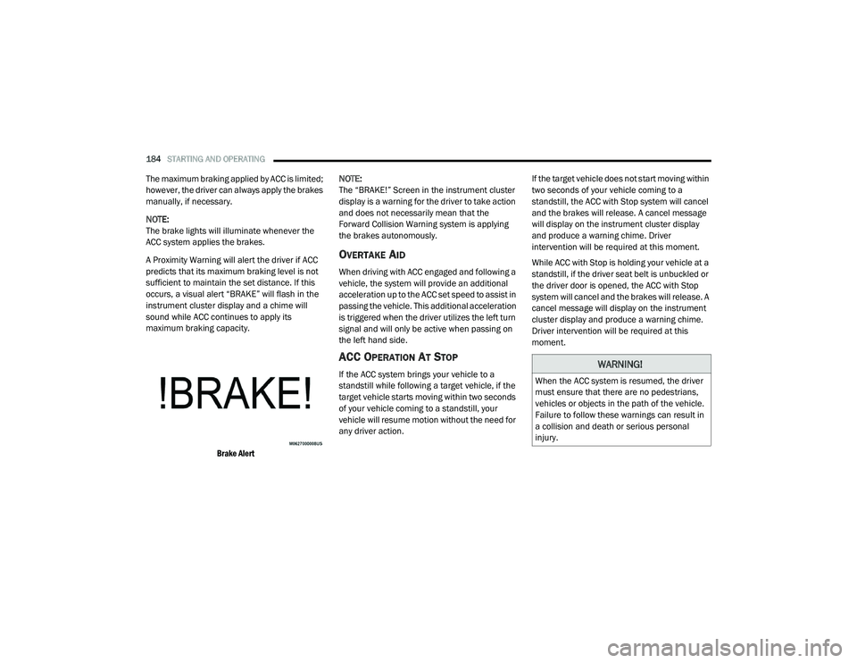
A Proximity Warning will alert the driver if ACC
predicts that its maximum braking level is not
sufficient to maintain the set distance. If this
occurs, a visual alert “BRAKE” will flash in the
instrument cluster display and a chime will
sound while ACC continues to apply its
maximum braking capacity.
Brake Alert
NOTE:
The “BRAKE!” Screen in the instrument cluster
display is a warning for the driver to take action
and does not necessarily mean that the
Forward Collision Warning system is applying
the brakes autonomously.
OVERTAKE AID
When driving with ACC engaged and following a
vehicle, the system will provide an additional
acceleration up to the ACC set speed to assist in
passing the vehicle. This additional acceleration
is triggered when the driver utilizes the left turn
signal and will only be active when passing on
the left hand side.
ACC OPERATION AT STOP
If the ACC system brings your vehicle to a
standstill while following a target vehicle, if the
target vehicle starts moving within two seconds
of your vehicle coming to a standstill, your
vehicle will resume motion without the need for
any driver action.
If the target vehicle does not start moving within
two seconds of your vehicle coming to a
standstill, the ACC with Stop system will cancel
and the brakes will release. A cancel message
will display on the instrument cluster display
and produce a warning chime. Driver
intervention will be required at this moment.
While ACC with Stop is holding your vehicle at a
standstill, if the driver seat belt is unbuckled or
the driver door is opened, the ACC with Stop
system will cancel and the brakes will release. A
cancel message will display on the instrument
cluster display and produce a warning chime.
Driver intervention will be required at this
moment.WARNING!
When the ACC system is resumed, the driver
must ensure that there are no pedestrians,
vehicles or objects in the path of the vehicle.
Failure to follow these warnings can result in
a collision and death or serious personal
injury.
20_LD_OM_EN_USC_t.book Page 184
Page 191 of 412
STARTING AND OPERATING189
Stationary Objects And Vehicles
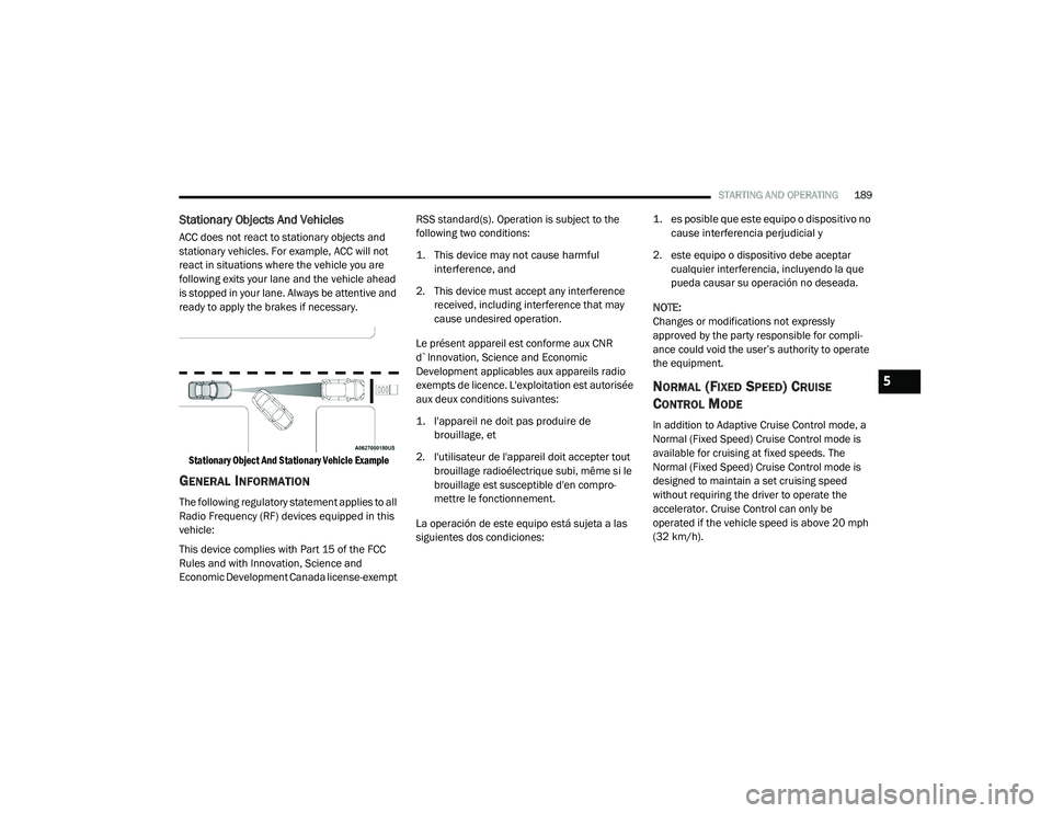
ACC does not react to stationary objects and
stationary vehicles. For example, ACC will not
react in situations where the vehicle you are
following exits your lane and the vehicle ahead
is stopped in your lane. Always be attentive and
ready to apply the brakes if necessary.
Stationary Object And Stationary Vehicle Example
GENERAL INFORMATION
The following regulatory statement applies to all
Radio Frequency (RF) devices equipped in this
vehicle:
This device complies with Part 15 of the FCC
Rules and with Innovation, Science and
Economic Development Canada license-exempt RSS standard(s). Operation is subject to the
following two conditions:
1. This device may not cause harmful
interference, and
2. This device must accept any interference received, including interference that may
cause undesired operation.
Le présent appareil est conforme aux CNR
d`Innovation, Science and Economic
Development applicables aux appareils radio
exempts de licence. L'exploitation est autorisée
aux deux conditions suivantes:
1. l'appareil ne doit pas produire de brouillage, et
2. l'utilisateur de l'appareil doit accepter tout brouillage radioélectrique subi, même si le
brouillage est susceptible d'en compro -
mettre le fonctionnement.
La operación de este equipo está sujeta a las
siguientes dos condiciones:
1. es posible que este equipo o dispositivo no
cause interferencia perjudicial y
2. este equipo o dispositivo debe aceptar cualquier interferencia, incluyendo la que
pueda causar su operación no deseada.
NOTE:
Changes or modifications not expressly
approved by the party responsible for compli -
ance could void the user’s authority to operate
the equipment.
NORMAL (FIXED SPEED) CRUISE
C
ONTROL MODE
In addition to Adaptive Cruise Control mode, a
Normal (Fixed Speed) Cruise Control mode is
available for cruising at fixed speeds. The
Normal (Fixed Speed) Cruise Control mode is
designed to maintain a set cruising speed
without requiring the driver to operate the
accelerator. Cruise Control can only be
operated if the vehicle speed is above 20 mph
(32 km/h).
5
20_LD_OM_EN_USC_t.book Page 189
Page 198 of 412

196STARTING AND OPERATING
(Continued)
object as a sensor problem, causing the
“PARKSENSE UNAVAILABLE SERVICE
REQUIRED” message to be shown in the
instrument cluster display.
LANESENSE — IF EQUIPPED
LANESENSE OPERATION
The LaneSense system is operational at speeds
above 37 mph (60 km/h) and below 112 mph
(180 km/h). The LaneSense system uses a
forward looking camera to detect lane markings
and measure vehicle position within the lane
boundaries.
When both lane markings are detected and the
driver unintentionally drifts out of the lane (no
turn signal applied), the LaneSense system
provides a haptic warning in the form of torque
applied to the steering wheel to prompt the
driver to remain within the lane boundaries. If
the driver continues to unintentionally drift out
of the lane, the LaneSense system provides a
visual warning through the instrument cluster
display to prompt the driver to remain within the
lane boundaries. The driver may manually override the haptic
warning by applying torque into the steering
wheel at any time.
When only a single lane marking is detected
and the driver unintentionally drifts across the
lane marking (no turn signal applied), the
LaneSense system provides visual warnings
through the instrument cluster display to
prompt the driver to remain within the lane.
When only a single lane marking is detected, a
haptic (torque) warning will not be provided.
NOTE:
When operating conditions have been met, the
LaneSense system will monitor if the driver’s
hands are on the steering wheel and provides
an audible warning to the driver when the
driver’s hands are not detected on the steering
wheel. The system will cancel if the driver does
not return their hands to the wheel.
TURNING LANESENSE ON OR OFF
The default status of LaneSense is off.
The LaneSense button is located on the center
stack below the Uconnect display.
WARNING!
Drivers must be careful when backing up
even when using the Rear Park Assist system.
Always check carefully behind your vehicle,
and be sure to check for pedestrians,
animals, other vehicles, obstructions, or blind
spots before backing up. You are responsible
for the safety of your surroundings and must
continue to pay attention while backing up.
Failure to do so can result in serious injury or
death.
CAUTION!
ParkSense is only a parking aid and it is
unable to recognize every obstacle,
including small obstacles. Parking curbs
might be temporarily detected or not
detected at all. Obstacles located above or
below the sensors will not be detected
when they are in close proximity.
The vehicle must be driven slowly when
using ParkSense in order to be able to stop
in time when an obstacle is detected. It is
recommended that the driver looks over
his/her shoulder when using ParkSense.
CAUTION!
(Continued)
20_LD_OM_EN_USC_t.book Page 196
Page 202 of 412
200STARTING AND OPERATING
Manual Activation Of The Rear View Camera:
1. Press the "Controls" button located on the
bottom of the Uconnect display.
2. Press the "Backup Camera" button to turn the Rear View Camera system on.
When manually activated, a counter will be
initiated after the vehicle speed is above 8 mph
(13 km/h). The rear view camera image will turn
off when this counter reaches 10 seconds. The
counter will be reset when the vehicle speed is
8 mph (13 km/h) or below.
If the vehicle speed remains below 8 mph
(13 km/h), the rear view camera image will
continue to be displayed until the transmission
is shifted into PARK, the vehicle’s ignition is
placed in the OFF position, or the image defeat
“X” button is pressed.
Different colored zones indicate the distance to
the rear of the vehicle. The following table shows the approximate
distances for each zone:
NOTE:
If snow, ice, mud, or any foreign substance
builds up on the camera lens, clean the lens,
rinse with water, and dry with a soft cloth. Do
not cover the lens.
REFUELING THE VEHICLE
1. Put the vehicle in PARK and switch the ignition off.
Zone
Distance To The Rear
Of The Vehicle
Red 0 - 1 ft (0 - 30 cm)
Yellow 1 ft - 6.5 ft
(30 cm - 2 m)
Green 6.5 ft or greater
(2 m or greater)
WARNING!
Drivers must be careful when backing up even
when using the ParkView Rear Back Up Camera.
Always check carefully behind your vehicle, and
be sure to check for pedestrians, animals, other
vehicles, obstructions, or blind spots before
backing up. You are responsible for the safety of
your surroundings and must continue to pay
attention while backing up. Failure to do so can
result in serious injury or death.
CAUTION!
To avoid vehicle damage, ParkView should
only be used as a parking aid. The ParkView
camera is unable to view every obstacle or
object in your drive path.
To avoid vehicle damage, the vehicle must
be driven slowly when using ParkView to be
able to stop in time when an obstacle is
seen. It is recommended that the driver
look frequently over his/her shoulder when
using ParkView.
20_LD_OM_EN_USC_t.book Page 200
Page 210 of 412
208STARTING AND OPERATING
Towing Requirements — Trailer Lights
And Wiring
Whenever you pull a trailer, regardless of the
trailer size, stoplights and turn signals on the
trailer are required for motoring safety.
The Trailer Tow Package may include a four- and
seven-pin wiring harness. Use a factory
approved trailer harness and connector.
NOTE:
Do not cut or splice wiring into the vehicle’s
wiring harness.
The electrical connections are all complete to
the vehicle but you must mate the harness to a
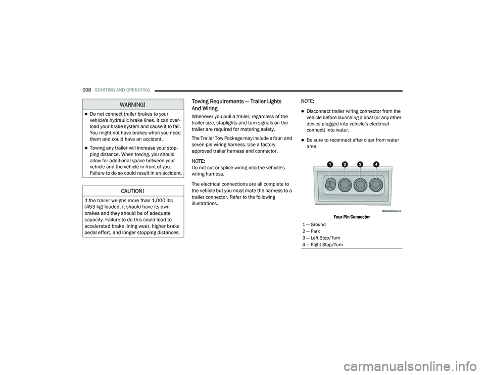
trailer connector. Refer to the following
illustrations. NOTE:Disconnect trailer wiring connector from the
vehicle before launching a boat (or any other
device plugged into vehicle’s electrical
connect) into water.
Be sure to reconnect after clear from water
area.
Four-Pin Connector
WARNING!
Do not connect trailer brakes to your
vehicle's hydraulic brake lines. It can over -
load your brake system and cause it to fail.
You might not have brakes when you need
them and could have an accident.
Towing any trailer will increase your stop -
ping distance. When towing, you should
allow for additional space between your
vehicle and the vehicle in front of you.
Failure to do so could result in an accident.
CAUTION!
If the trailer weighs more than 1,000 lbs
(453 kg) loaded, it should have its own
brakes and they should be of adequate
capacity. Failure to do this could lead to
accelerated brake lining wear, higher brake
pedal effort, and longer stopping distances.
1 — Ground
2 — Park
3 — Left Stop/Turn
4 — Right Stop/Turn
20_LD_OM_EN_USC_t.book Page 208
Page 211 of 412
STARTING AND OPERATING209
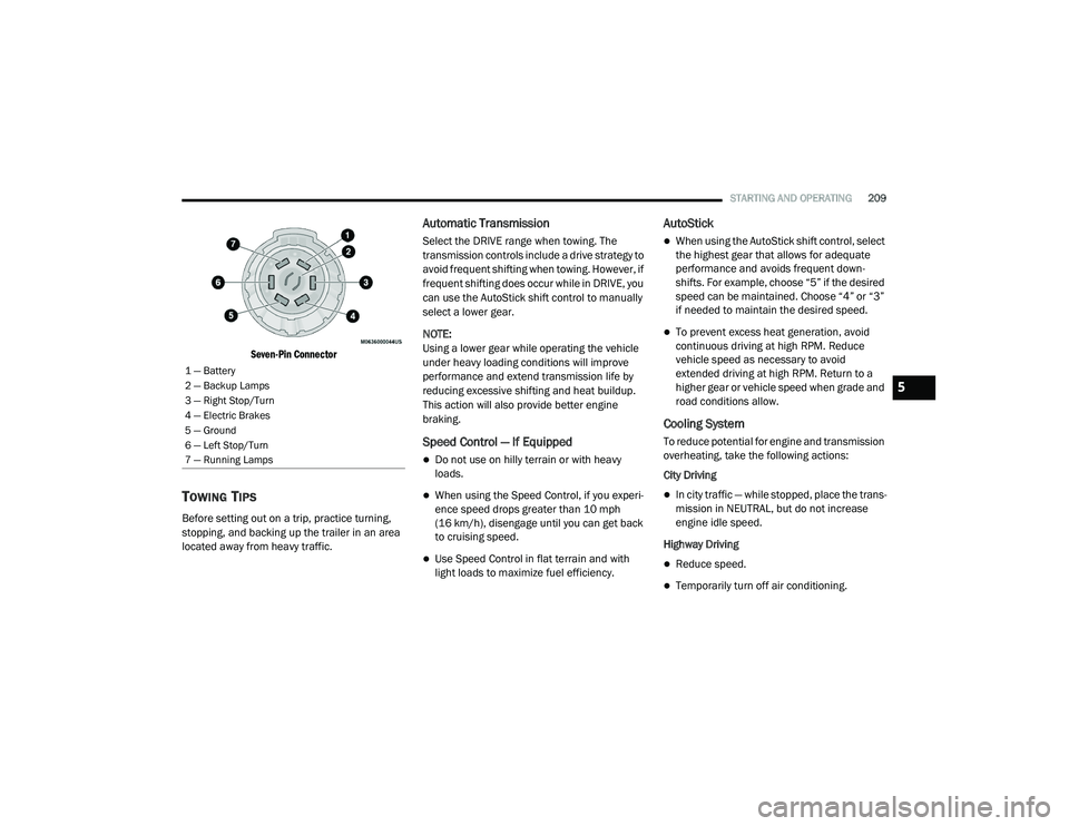
Seven-Pin Connector
TOWING TIPS
Before setting out on a trip, practice turning,
stopping, and backing up the trailer in an area
located away from heavy traffic.
Automatic Transmission
Select the DRIVE range when towing. The
transmission controls include a drive strategy to
avoid frequent shifting when towing. However, if
frequent shifting does occur while in DRIVE, you
can use the AutoStick shift control to manually
select a lower gear.
NOTE:
Using a lower gear while operating the vehicle
under heavy loading conditions will improve
performance and extend transmission life by
reducing excessive shifting and heat buildup.
This action will also provide better engine
braking.
Speed Control — If Equipped
Do not use on hilly terrain or with heavy
loads.
When using the Speed Control, if you experi -
ence speed drops greater than 10 mph
(16 km/h), disengage until you can get back
to cruising speed.
Use Speed Control in flat terrain and with
light loads to maximize fuel efficiency.
AutoStick
When using the AutoStick shift control, select
the highest gear that allows for adequate
performance and avoids frequent down -
shifts. For example, choose “5” if the desired
speed can be maintained. Choose “4” or “3”
if needed to maintain the desired speed.
To prevent excess heat generation, avoid
continuous driving at high RPM. Reduce
vehicle speed as necessary to avoid
extended driving at high RPM. Return to a
higher gear or vehicle speed when grade and
road conditions allow.
Cooling System
To reduce potential for engine and transmission
overheating, take the following actions:
City Driving
In city traffic — while stopped, place the trans -
mission in NEUTRAL, but do not increase
engine idle speed.
Highway Driving
Reduce speed.
Temporarily turn off air conditioning.
1 — Battery
2 — Backup Lamps
3 — Right Stop/Turn
4 — Electric Brakes
5 — Ground
6 — Left Stop/Turn
7 — Running Lamps
5
20_LD_OM_EN_USC_t.book Page 209
Page 212 of 412
210STARTING AND OPERATING
RECREATIONAL TOWING (BEHIND
MOTORHOME, ETC.)
Recreational towing (with all four wheels on the
ground, or using a tow dolly) is NOT ALLOWED.
The only acceptable method for towing this
vehicle (behind another vehicle) is on a vehicle
trailer with all four wheels OFF the ground.
DRIVING TIPS
DRIVING ON SLIPPERY SURFACES
Information in this section will aid in safe
controlled launches in adverse conditions.
Acceleration
Rapid acceleration on snow covered, wet, or
other slippery surfaces may cause the driving
wheels to pull erratically to the right or left. This
phenomenon occurs when there is a difference
in the surface traction under the front (driving)
wheels.
Traction
When driving on wet or slushy roads, it is
possible for a wedge of water to build up
between the tire and road surface. This is
known as hydroplaning and may cause partial or complete loss of vehicle control and stopping
ability. To reduce this possibility, the following
precautions should be observed:
Slow down during rainstorms or when the
roads are slushy.
Slow down if the road has standing water or
puddles.
Replace tires when tread wear indicators first
become visible.
Keep tires properly inflated.
Maintain sufficient distance between your
vehicle and the vehicle in front of you to avoid
a collision in a sudden stop.
Your vehicle may be equipped with a Limited
Slip Differential (LSD) that reduces, but does
not eliminate, the amount of wheel slip across a
given axle for improved handling.
CAUTION!
Towing this vehicle in violation of the above
requirements can cause severe transmission
and/or transfer case damage. Damage from
improper towing is not covered under the New
Vehicle Limited Warranty.
WARNING!
Rapid acceleration on slippery surfaces is
dangerous. Unequal traction can cause
sudden pulling of the front wheels. You could
lose control of the vehicle and possibly have a
collision. Accelerate slowly and carefully
whenever there is likely to be poor traction
(ice, snow, wet, mud, loose sand, etc.).
20_LD_OM_EN_USC_t.book Page 210