2020 DODGE CHARGER parking brake
[x] Cancel search: parking brakePage 232 of 412
230IN CASE OF EMERGENCY
JACK LOCATION/SPARE TIRE STOWAGE
The jack and spare tire are both stowed under
an access cover in the trunk. Follow these steps
to access the jack and spare tire.
NOTE:
The spare tire must be removed in order to
access the jack.
1. Open the trunk.
2. Lift the access cover using the pull strap.
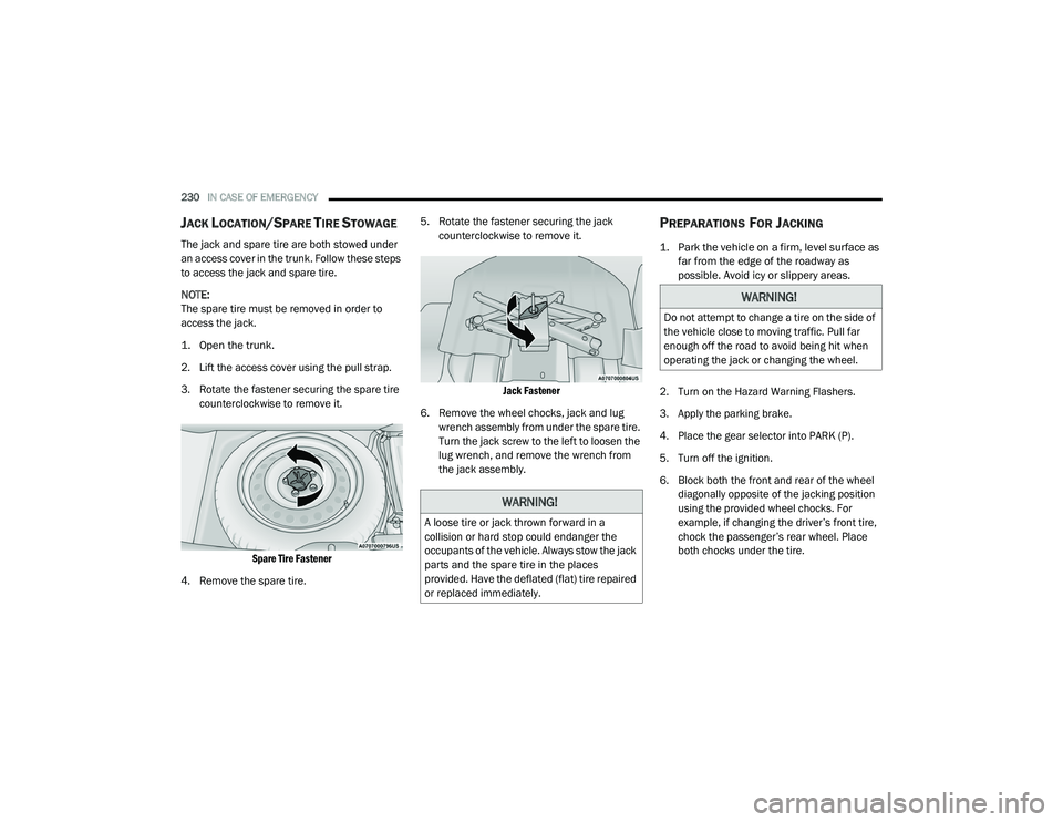
3. Rotate the fastener securing the spare tire
counterclockwise to remove it.
Spare Tire Fastener
4. Remove the spare tire. 5. Rotate the fastener securing the jack
counterclockwise to remove it.
Jack Fastener
6. Remove the wheel chocks, jack and lug wrench assembly from under the spare tire.
Turn the jack screw to the left to loosen the
lug wrench, and remove the wrench from
the jack assembly.
PREPARATIONS FOR JACKING
1. Park the vehicle on a firm, level surface as far from the edge of the roadway as
possible. Avoid icy or slippery areas.
2. Turn on the Hazard Warning Flashers.
3. Apply the parking brake.
4. Place the gear selector into PARK (P).
5. Turn off the ignition.
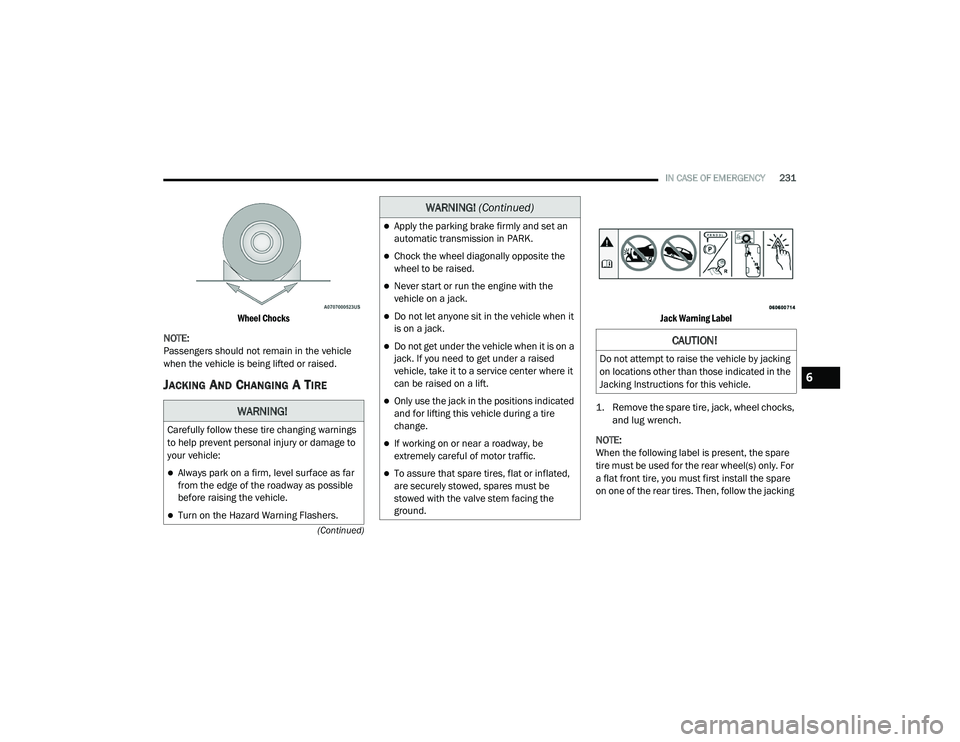
6. Block both the front and rear of the wheel diagonally opposite of the jacking position
using the provided wheel chocks. For
example, if changing the driver’s front tire,
chock the passenger’s rear wheel. Place
both chocks under the tire.
WARNING!
A loose tire or jack thrown forward in a
collision or hard stop could endanger the
occupants of the vehicle. Always stow the jack
parts and the spare tire in the places
provided. Have the deflated (flat) tire repaired
or replaced immediately.
WARNING!
Do not attempt to change a tire on the side of
the vehicle close to moving traffic. Pull far
enough off the road to avoid being hit when
operating the jack or changing the wheel.
20_LD_OM_EN_USC_t.book Page 230
Page 233 of 412
IN CASE OF EMERGENCY231
(Continued)
Wheel Chocks
NOTE:
Passengers should not remain in the vehicle
when the vehicle is being lifted or raised.
JACKING AND CHANGING A TIRE
Jack Warning Label
1. Remove the spare tire, jack, wheel chocks, and lug wrench.
NOTE:
When the following label is present, the spare
tire must be used for the rear wheel(s) only. For
a flat front tire, you must first install the spare
on one of the rear tires. Then, follow the jacking
WARNING!
Carefully follow these tire changing warnings
to help prevent personal injury or damage to
your vehicle:
Always park on a firm, level surface as far
from the edge of the roadway as possible
before raising the vehicle.
Turn on the Hazard Warning Flashers.
Apply the parking brake firmly and set an
automatic transmission in PARK.
Chock the wheel diagonally opposite the
wheel to be raised.
Never start or run the engine with the
vehicle on a jack.
Do not let anyone sit in the vehicle when it
is on a jack.
Do not get under the vehicle when it is on a
jack. If you need to get under a raised
vehicle, take it to a service center where it
can be raised on a lift.
Only use the jack in the positions indicated
and for lifting this vehicle during a tire
change.
If working on or near a roadway, be
extremely careful of motor traffic.
To assure that spare tires, flat or inflated,
are securely stowed, spares must be
stowed with the valve stem facing the
ground.
WARNING! (Continued)
CAUTION!
Do not attempt to raise the vehicle by jacking
on locations other than those indicated in the
Jacking Instructions for this vehicle.
6
20_LD_OM_EN_USC_t.book Page 231
Page 239 of 412
IN CASE OF EMERGENCY237
SEALING A TIRE WITH TIRE SERVICE KIT
(A) Whenever You Stop To Use Tire Service
Kit:
1. Pull over to a safe location and turn on the
vehicle’s Hazard Warning flashers.
2. Verify that the valve stem (on the wheel with the deflated tire) is in a position that is near
to the ground. This will allow the Tire Service
Kit Hoses (6) and (7) to reach the valve
stem and keep the Tire Service Kit flat on
the ground. This will provide the best
positioning of the kit when injecting the
sealant into the deflated tire and running
the air pump. Move the vehicle as
necessary to place the valve stem in this
position before proceeding.
3. Place the transmission in PARK (auto transmission) or in Gear (manual
transmission) and place the ignition in the
OFF position.
4. Apply the parking brake.
(B) Setting Up To Use Tire Service Kit:
1. Push in the Mode Select Knob (5) and turn to the Sealant Mode position.
2. Uncoil the Sealant Hose (6) and then
remove the cap from the fitting at the end of
the hose.
3. Place the Tire Service Kit flat on the ground next to the deflated tire.
4. Remove the cap from the valve stem and then screw the fitting at the end of the
Sealant Hose (6) onto the valve stem.
5. Uncoil the Power Plug (8) and insert the plug into the vehicle’s 12 Volt power outlet.
NOTE:
Do not remove foreign objects (e.g., screws or
nails) from the tire.
(C) Injecting Tire Service Kit Sealant Into
The Deflated Tire:
Always start the engine before turning ON the
Tire Service Kit.
NOTE:
Manual transmission vehicles must have the
parking brake engaged and the gear selector in
NEUTRAL.
After pushing the Power Button (4), the
sealant (white fluid) will flow from the Sealant
Bottle (1) through the Sealant Hose (6) and
into the tire.
NOTE:
Sealant may leak out through the puncture in
the tire.
If the sealant (white fluid) does not flow within 0
– 10 seconds through the Sealant Hose (6):
1. Push the Power Button (4) to turn Off the Tire Service Kit. Disconnect the Sealant
Hose (6) from the valve stem. Make sure
the valve stem is free of debris. Reconnect
the Sealant Hose (6) to the valve stem.
Check that the Mode Select Knob (5) is in
the Sealant Mode position and not Air
Mode. Push the Power Button (4) to turn
On the Tire Service Kit.
2. Connect the Power Plug (8) to a different 12 Volt power outlet in your vehicle or
another vehicle, if available. Make sure the
engine is running before turning ON the
Tire Service Kit.
6
20_LD_OM_EN_USC_t.book Page 237
Page 243 of 412

IN CASE OF EMERGENCY241
1. Apply the parking brake, shift the
automatic transmission into PARK and
place the ignition in the OFF position.
2. Turn off the heater, radio, and all unnecessary electrical accessories.
3. If using another vehicle to jump start the battery, park the vehicle within the jumper
cable’s reach, apply the parking brake and
make sure the ignition is OFF.
JUMP STARTING PROCEDURE
1. Connect the positive
(+) end of the jumper
cable to the remote positive (+)
post of the
vehicle with the discharged battery.
2. Connect the opposite end of the positive (+)
jumper cable to the positive (+) post of the
booster battery.
3. Connect the negative (-) end of the jumper
cable to the negative (-) post of the booster
battery.
4. Connect the opposite end of the negative (-)
jumper cable to the remote negative (-) post
of the vehicle with the discharged battery. 5. Start the engine in the vehicle that has the
booster battery, let the engine idle a few
minutes, and then start the engine in the
vehicle with the discharged battery.
6. Once the engine is started, remove the jumper cables in the reverse sequence.
Disconnecting The Jumper Cables
1. Disconnect the negative
(-) end of the
jumper cable from the remote negative (-)
post of the vehicle with the discharged
battery.
2. Disconnect the opposite end of the negative (-) jumper cable from the negative (-) post of
the booster battery.
Batteries contain sulfuric acid that can
burn your skin or eyes and generate
hydrogen gas which is flammable and
explosive. Keep open flames or sparks
away from the battery.
WARNING!
Do not allow vehicles to touch each other as
this could establish a ground connection and
personal injury could result.
WARNING! (Continued)
WARNING!
Failure to follow this jump starting procedure
could result in personal injury or property
damage due to battery explosion.
CAUTION!
Failure to follow these procedures could
result in damage to the charging system of
the booster vehicle or the discharged vehicle.
WARNING!
Do not connect the jumper cable to the
negative (-) post of the discharged battery. The
resulting electrical spark could cause the
battery to explode and could result in personal
injury. Only use the specific ground point, do
not use any other exposed metal parts.
6
20_LD_OM_EN_USC_t.book Page 241
Page 245 of 412

IN CASE OF EMERGENCY243
MANUAL PARK RELEASE — 8 – SPEED
TRANSMISSION
To move the vehicle in cases where the
transmission will not shift out of PARK (such as
a depleted battery), a Manual Park Release is
available.
Follow these steps to use the Manual Park
Release:
1. Firmly apply the parking brake.
2. Remove the console storage bin.
Console Storage Bin
Manual Park Release Cover
3. Remove the plastic cover under the bin by using the slot provided to access the
Manual Park Release lever.
4. Using a small screwdriver or similar tool, fish the tether strap up through the opening
in the console base. 5. Press and maintain firm pressure on the
brake pedal.
6. Insert the screwdriver into the slot in the center of the lever, and disengage the lever
locking tab by pushing it to the right.
Engaging The Lever
7. While holding the locking tab in the disengaged position, pull the tether strap to
rotate the lever up and rearward, until it
locks in place in the vertical position. The
vehicle is now out of PARK and can be
moved. Release the parking brake only
when the vehicle is securely connected to a
tow vehicle.
WARNING!
Always secure your vehicle by fully applying
the parking brake before activating the
Manual Park Release. In addition, you should
be seated in the driver's seat with your foot
firmly on the brake pedal when activating the
Manual Park Release. Activating the Manual
Park Release will allow your vehicle to roll
away if it is not secured by the parking brake,
or by proper connection to a tow vehicle.
Activating the Manual Park Release on an
unsecured vehicle could lead to serious injury
or death for those in or around the vehicle.
6
20_LD_OM_EN_USC_t.book Page 243
Page 261 of 412

SERVICING AND MAINTENANCE259
Adjust the
parking
brake on
vehicles
equipped
with four
wheel disc
brakes.X
XX X X
Miles:
6,000
12,000
18,000
24,000
30,000
36,000
42,000
48,000
54,000
60,000
66,000
72,000
78,000
84,000
90,000
96,000
102,000
108,000
114,000
120,000
126,000
132,000
138,000
144,000
150,000
Or Months:
6 12 18 24 30 36 42 48 54 60 66 72 78 84 90 96 102 108 114 120 126 132 138 144 150
Or
Kilometers:
10,000
20,000
30,000
40,000
50,000
60,000
70,000
80,000
90,000
100,000
110,000
120,000
130,000
140,000
150,000
160,000
170,000
180,000
190,000
200,000
210,000
220,000
230,000
240,000
250,000
7
20_LD_OM_EN_USC_t.book Page 259
Page 303 of 412
SERVICING AND MAINTENANCE301
When cleaning extremely dirty wheels including
excessive brake dust, care must be taken in the
selection of tire and wheel cleaning chemicals
and equipment to prevent damage to the wheels.
Mopar Wheel Treatment or Mopar Chrome
Cleaner or their equivalent is recommended or
select a non-abrasive, non-acidic cleaner for
aluminum or chrome wheels.
NOTE:
If you intend parking or storing your vehicle for
an extended period after cleaning the wheels
with wheel cleaner, drive your vehicle and apply
the brakes to remove the water droplets from
the brake components. This activity will remove
the red rust on the brake rotors and prevent
vehicle vibration when braking. Dark Vapor Chrome, Black Satin Chrome, or
Low Gloss Clear Coat Wheels
TIRE CHAINS AND TRACTION DEVICES —
N
ON-SRT
Use of traction devices require sufficient
tire-to-body clearance. Due to limited clearance,
the following traction devices are
recommended. Follow these recommendations
to guard against damage.
Traction device must be of proper size for the
tire, as recommended by the traction device
manufacturer.
No other tire sizes are recommended for use
with a tire chain or traction device.
Install on rear tires only.
Rear Wheel Drive (RWD) Models
For a P215/65R17 tire, use a Peerless Chain
Super Z6 low profile traction device or
equivalent is recommended.
All Wheel Drive (AWD) Models
For a P235/55R19 tire, use of an S Class
traction device or equivalent is recommended.
CAUTION!
Do not use scouring pads, steel wool, a bristle
brush, metal polishes or oven cleaner. These
products may damage the wheel's protective
finish. Such damage is not covered by the
New Vehicle Limited Warranty. Only car wash
soap, Mopar Wheel Cleaner or equivalent is
recommended.
CAUTION!
If your vehicle is equipped with these
specialty wheels, DO NOT USE wheel
cleaners, abrasives, or polishing compounds.
They will permanently damage this finish and
such damage is not covered by the New
Vehicle Limited Warranty. HAND WASH ONLY
USING MILD SOAP AND WATER WITH A SOFT
CLOTH. Used on a regular basis; this is all that
is required to maintain this finish.
WARNING!
Using tires of different size and type (M+S,
Snow) between front and rear axles can
cause unpredictable handling. You could lose
control and have a collision.
7
20_LD_OM_EN_USC_t.book Page 301
Page 329 of 412
MULTIMEDIA327
Safety & Driving Assistance
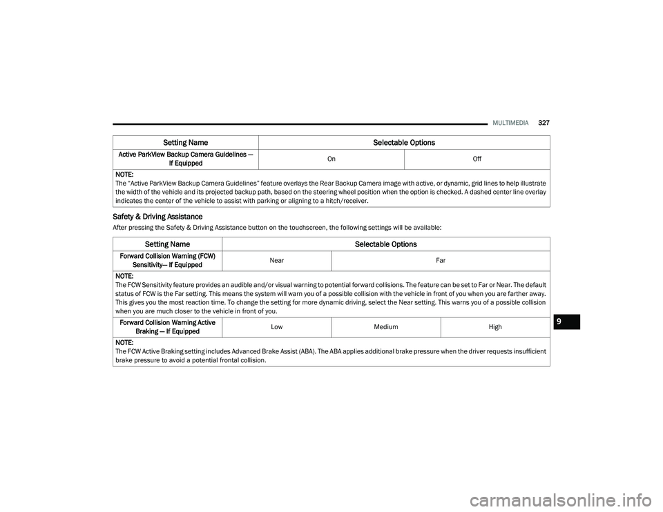
After pressing the Safety & Driving Assistance button on the touchscreen, the following settings will be available:Active ParkView Backup Camera Guidelines —
If Equipped On
Off
NOTE:
The “Active ParkView Backup Camera Guidelines” feature overlays the Rear Backup Camera image with active, or dynamic, grid lines to help illustrate
the width of the vehicle and its projected backup path, based on the steering wheel position when the option is checked. A dashed center line overlay
indicates the center of the vehicle to assist with parking or aligning to a hitch/receiver.
Setting Name Selectable Options
Setting NameSelectable Options
Forward Collision Warning (FCW)
Sensitivity— If Equipped Near
Far
NOTE:
The FCW Sensitivity feature provides an audible and/or visual warning to potential forward collisions. The feature can be set to Far or Near. The default
status of FCW is the Far setting. This means the system will warn you of a possible collision with the vehicle in front of you when you are farther away.
This gives you the most reaction time. To change the setting for more dynamic driving, select the Near setting. This warns you of a possible collision
when you are much closer to the vehicle in front of you. Forward Collision Warning Active Braking — If Equipped Low
Medium High
NOTE:
The FCW Active Braking setting includes Advanced Brake Assist (ABA). The ABA applies additional brake pressure when the driver requests insufficient
brake pressure to avoid a potential frontal collision.
9
20_LD_OM_EN_USC_t.book Page 327