2020 DODGE CHARGER fuel
[x] Cancel search: fuelPage 202 of 412
200STARTING AND OPERATING
Manual Activation Of The Rear View Camera:
1. Press the "Controls" button located on the
bottom of the Uconnect display.
2. Press the "Backup Camera" button to turn the Rear View Camera system on.
When manually activated, a counter will be
initiated after the vehicle speed is above 8 mph
(13 km/h). The rear view camera image will turn
off when this counter reaches 10 seconds. The
counter will be reset when the vehicle speed is
8 mph (13 km/h) or below.
If the vehicle speed remains below 8 mph
(13 km/h), the rear view camera image will
continue to be displayed until the transmission
is shifted into PARK, the vehicle’s ignition is
placed in the OFF position, or the image defeat
“X” button is pressed.
Different colored zones indicate the distance to
the rear of the vehicle. The following table shows the approximate
distances for each zone:
NOTE:
If snow, ice, mud, or any foreign substance
builds up on the camera lens, clean the lens,
rinse with water, and dry with a soft cloth. Do
not cover the lens.
REFUELING THE VEHICLE
1. Put the vehicle in PARK and switch the ignition off.
Zone
Distance To The Rear
Of The Vehicle
Red 0 - 1 ft (0 - 30 cm)
Yellow 1 ft - 6.5 ft
(30 cm - 2 m)
Green 6.5 ft or greater
(2 m or greater)
WARNING!
Drivers must be careful when backing up even
when using the ParkView Rear Back Up Camera.
Always check carefully behind your vehicle, and
be sure to check for pedestrians, animals, other
vehicles, obstructions, or blind spots before
backing up. You are responsible for the safety of
your surroundings and must continue to pay
attention while backing up. Failure to do so can
result in serious injury or death.
CAUTION!
To avoid vehicle damage, ParkView should
only be used as a parking aid. The ParkView
camera is unable to view every obstacle or
object in your drive path.
To avoid vehicle damage, the vehicle must
be driven slowly when using ParkView to be
able to stop in time when an obstacle is
seen. It is recommended that the driver
look frequently over his/her shoulder when
using ParkView.
20_LD_OM_EN_USC_t.book Page 200
Page 203 of 412
STARTING AND OPERATING201
2. Push near the rear edge and center of the of
the fuel filler door to release. The door will
pop open to allow hand access to open the
door the rest of the way.
Fuel Filler Door
3. Open the fuel filler door.
Fuel Filler
NOTE:
In certain cold conditions, ice may prevent the
fuel door from opening. If this occurs, lightly
push on the fuel door to break the ice buildup.
4. There is no fuel filler cap. A flapper door
inside the pipe seals the system.
5. Insert the fuel nozzle fully into the filler pipe – the nozzle opens and holds the flapper
door while refueling.
6. Fill the vehicle with fuel – when the fuel nozzle “clicks” or shuts off the fuel tank is
full.
7. Maintain nozzle in filler for five seconds to allow nozzle to drain.
8. Remove the fuel nozzle and close the fuel door.
9. To close the fuel filler door, push the center-rear edge (three o’clock position) of
the fuel filler door then release.
NOTE:
A funnel is provided (located in the trunk in the
spare tire area) to open the flapper door to allow
for emergency refueling with a gas can.
Fuel Funnel
WARNING!
Never have any smoking materials lit in or
near the vehicle when the fuel door is open
or the tank is being filled.
Never add fuel when the engine is running.
This is in violation of most state and federal
fire regulations and may cause the
“Malfunction Indicator Light” to turn on.
A fire may result if fuel is pumped into a
portable container that is inside of a
vehicle. You could be burned. Always place
fuel containers on the ground while filling.
5
20_LD_OM_EN_USC_t.book Page 201
Page 204 of 412

202STARTING AND OPERATING
VEHICLE LOADING
The load carrying capacity of your vehicle is
shown on the “Vehicle Certification Label”. This
information should be used for passenger and
luggage loading as indicated.
Do not exceed the specified Gross Vehicle
Weight Rating (GVWR) or the Gross Axle Weight
Rating (GAWR).
VEHICLE CERTIFICATION LABEL
Your vehicle has a Vehicle Certification Label
affixed to the drivers side B-pillar or the rear of
the driver’s door.
The label contains the following information:
Name of manufacturer
Month and year of manufacture
Gross Vehicle Weight Rating (GVWR)
Gross Axle Weight Rating (GAWR) front
Gross Axle Weight Rating (GAWR) rear
Vehicle Identification Number (VIN)
Type of vehicle
Month, Day, and Hour of manufacture (MDH)
The bar code allows a computer scanner to read
the VIN.
GROSS VEHICLE WEIGHT RATING
(GVWR)
The GVWR is the total allowable weight of your
vehicle. This includes driver, passengers, and
cargo. The total load must be limited so that you
do not exceed the GVWR.
GROSS AXLE WEIGHT RATING (GAWR)
The GAWR is the maximum capacity of the front
and rear axles. Distribute the load over the front
and rear axles evenly. Make sure that you do
not exceed either front or rear GAWR.
OVERLOADING
The load carrying components (axle, springs,
tires, wheels, etc.) of your vehicle will provide
satisfactory service as long as you do not
exceed the GVWR and the front and rear GAWR.
The best way to figure out the total weight of
your vehicle is to weigh it when it is fully loaded
and ready for operation. Weigh it on a
commercial scale to ensure that it is not over
the GVWR.
Figure out the weight on the front and rear of
the vehicle separately. It is important that you
distribute the load evenly over the front and rear
axles.
CAUTION!
To avoid fuel spillage and overfilling, do not
“top off” the fuel tank after filling.
WARNING!
Because the front wheels steer the vehicle, it
is important that you do not exceed the
maximum front or rear GAWR. A dangerous
driving condition can result if either rating is
exceeded. You could lose control of the
vehicle and have a collision.
20_LD_OM_EN_USC_t.book Page 202
Page 211 of 412
STARTING AND OPERATING209
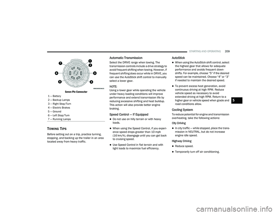
Seven-Pin Connector
TOWING TIPS
Before setting out on a trip, practice turning,
stopping, and backing up the trailer in an area
located away from heavy traffic.
Automatic Transmission
Select the DRIVE range when towing. The
transmission controls include a drive strategy to
avoid frequent shifting when towing. However, if
frequent shifting does occur while in DRIVE, you
can use the AutoStick shift control to manually
select a lower gear.
NOTE:
Using a lower gear while operating the vehicle
under heavy loading conditions will improve
performance and extend transmission life by
reducing excessive shifting and heat buildup.
This action will also provide better engine
braking.
Speed Control — If Equipped
Do not use on hilly terrain or with heavy
loads.
When using the Speed Control, if you experi -
ence speed drops greater than 10 mph
(16 km/h), disengage until you can get back
to cruising speed.
Use Speed Control in flat terrain and with
light loads to maximize fuel efficiency.
AutoStick
When using the AutoStick shift control, select
the highest gear that allows for adequate
performance and avoids frequent down -
shifts. For example, choose “5” if the desired
speed can be maintained. Choose “4” or “3”
if needed to maintain the desired speed.
To prevent excess heat generation, avoid
continuous driving at high RPM. Reduce
vehicle speed as necessary to avoid
extended driving at high RPM. Return to a
higher gear or vehicle speed when grade and
road conditions allow.
Cooling System
To reduce potential for engine and transmission
overheating, take the following actions:
City Driving
In city traffic — while stopped, place the trans -
mission in NEUTRAL, but do not increase
engine idle speed.
Highway Driving
Reduce speed.
Temporarily turn off air conditioning.
1 — Battery
2 — Backup Lamps
3 — Right Stop/Turn
4 — Electric Brakes
5 — Ground
6 — Left Stop/Turn
7 — Running Lamps
5
20_LD_OM_EN_USC_t.book Page 209
Page 228 of 412

226IN CASE OF EMERGENCY
F8 30 Amp Pink –Interior Lighting
F9 40 Amp Green –Power Locks
F10 30 Amp Pink –Driver Door Control Module
F11 30 Amp Pink –Passenger Door Control Module
F12 –20 Amp YellowCigar Lighter/IP APO/RR USB
(Selectable Fuse)– If Equipped
F15 40 Amp Green –HVAC Blower
F16 20 Amp Blue –Left Spot Lamp – Police
F17 20 Amp Blue –Right Spot Lamp – Police
F18 30 Amp Pink –VISM Mod (Police)
F19 ––Fuse – Spare
F20 ––Fuse – Spare
F21 30 Amp Pink –Fuel Pump (Non 6.2L ADR)
F22 –5 Amp Tan Cyber Gateway Mod
F23 –10 Amp RedFuel Door – If Equipped/Diagnostic
Port
F24 –10 Amp RedIntegrated Center Stack
F25 –10 Amp Red Tire Pressure Monitor
F26 –15 Amp BlueTrans Mod (Charger Non- Police/
300)
F27 –25 Amp Clear Amplifier – If Equipped
CavityCartridge Fuse Mini-FuseDescription
20_LD_OM_EN_USC_t.book Page 226
Page 229 of 412
IN CASE OF EMERGENCY227
F31 –25 Amp Breaker Power Seats – If Equipped
F32 –15 Amp Blue HVAC Module/Cluster
F33 –15 Amp BlueIgnition Switch/Wireless Mod/
Steer Column Lock Mod/Remote Start – If Equipped
F34 –10 Amp RedSteering Column Module/Clock
(300)
F35 –5 Amp Tan Battery Sensor
F36 –15 Amp BlueElectronic Exhaust Valve –
If Equipped
F37 –20 Amp Yellow Radio
F38 –20 Amp Yellow Media Hub/ Console APO
F40 30 Amp Pink –Fuel Pump #1 (6.2L ADR) –
If Equipped
F41 30 Amp Pink –Fuel Pump #2 (6.2L ADR) –
If Equipped
F42 30 Amp Pink –Rear Defrost
F43 –20 Amp YellowRR Heated Seat – If Equipped/
Heated Steering Wheel – If Equipped
F44 –10 Amp RedPark Assist / Blind Spot / Rear
View Camera – If Equipped
Cavity Cartridge Fuse Mini-FuseDescription
6
20_LD_OM_EN_USC_t.book Page 227
Page 257 of 412
SERVICING AND MAINTENANCE255
An authorized dealer will reset the oil change
indicator message after completing the
scheduled oil change. If a scheduled oil change
is performed by someone other than an
authorized dealer, the message can be reset by
referring to the steps described under
“Instrument Cluster Display” in “Getting To
Know Your Instrument Panel” for further
information.
At Each Stop For Fuel
Check the engine oil level. Refer to “Engine
Compartment” in this chapter for further
information.
Check the windshield washer solvent and
add if required. Once A Month
Check tire pressure and look for unusual
wear or damage.
Inspect the battery, and clean and tighten the
terminals as required.
Check the fluid levels of the coolant reservoir,
brake master cylinder, and power steering
(6.2L only), and add as needed.
Check all lights and other electrical items for
correct operation.
At Each Oil Change
Change the engine oil filter.
Inspect the brake hoses and lines.
Inspect the CV/Universal joints.
CAUTION!
Failure to perform the required maintenance
items may result in damage to the vehicle.
7
20_LD_OM_EN_USC_t.book Page 255
Page 275 of 412

SERVICING AND MAINTENANCE273
Engine Oil Selection — 6.2L And 6.4L
Engine
For best performance and maximum protection
under all types of operating conditions, the
manufacturer only recommends full synthetic
engine oils that meet the American Petroleum
Institute (API) categories of SN.
The manufacturer recommends the use of a full
synthetic SAE 0W-40 engine oil or equivalent
meeting the requirements of FCA Material
Standard MS-12633.
NOTE:
Hemi engines at times can tick right after
startup and then quiet down after approxi -
mately 30 seconds. This is normal and will not
harm the engine. This characteristic can be
caused by short drive cycles. For example, if the
vehicle is started then shut off after driving a
short distance. Upon restarting, you may experi -
ence a ticking sound. Other causes could be if
the vehicle is unused for an extended period of
time, incorrect oil, extended oil changes or
extended idling. If the engine continues to tick
or if the Malfunction Indicator Light (MIL) comes
on, see the nearest authorized dealer.
American Petroleum Institute (API) Engine
Oil Identification Symbol
This symbol means that the oil has
been certified by the American
Petroleum Institute (API). The
manufacturer only recommends API
Certified engine oils.
This symbol certifies 0W-20, 5W-20, 0W-30,
5W-30 and 10W-30 engine oils.
Engine Oil Viscosity (SAE Grade) — 3.6L
Engine
Mopar SAE 5W-20 engine oil approved to FCA
Material Standard MS-6395 such as Pennzoil,
Shell Helix Ultra or equivalent is recommended
for all operating temperatures. This engine oil
improves low temperature starting and vehicle
fuel economy.
The engine oil filler cap also shows the
recommended engine oil viscosity for your
engine. For information on engine oil filler cap
location, refer to the “Engine Compartment”
illustration in this section.
NOTE:
Mopar SAE 5W-30 engine oil approved to FCA
Material Standard MS-6395 such as Pennzoil,
Shell Helix Ultra or equivalent may be used
when SAE 5W-20 engine oil meeting MS-6395
is not available.
Lubricants which do not have both the engine
oil certification mark and the correct SAE
viscosity grade number should not be used.
CAUTION!
Do not use chemical flushes in your engine oil
as the chemicals can damage your engine.
Such damage is not covered by the New
Vehicle Limited Warranty.
CAUTION!
Do not use chemical flushes in your engine oil
as the chemicals can damage your engine.
Such damage is not covered by the New
Vehicle Limited Warranty.
7
20_LD_OM_EN_USC_t.book Page 273