2020 CHRYSLER 300 brake
[x] Cancel search: brakePage 171 of 328

STARTING AND OPERATING169
instrument cluster displays the “Sensed Vehicle
Indicator” icon, and the system adjusts vehicle
speed automatically to maintain the distance
setting, regardless of the set speed.
The vehicle will then maintain the set distance
until:
The vehicle ahead accelerates to a speed
above the set speed.
The vehicle ahead moves out of your lane or
view of the sensor.
The distance setting is changed.
The system disengages. (Refer to the infor -
mation on ACC Activation).
The maximum braking applied by ACC is limited;
however, the driver can always apply the brakes
manually, if necessary.
NOTE:
The brake lights will illuminate whenever the
ACC system applies the brakes.
A Proximity Warning will alert the driver if ACC
predicts that its maximum braking level is not
sufficient to maintain the set distance. If this
occurs, a visual alert “BRAKE” will flash in the instrument cluster display and a chime will
sound while ACC continues to apply its
maximum braking capacity.
Brake Alert
NOTE:
The “BRAKE!” screen in the instrument cluster
display is a warning for the driver to take action
and does not necessarily mean that the
Forward Collision Warning system is applying
the brakes autonomously.
OVERTAKE AID
When driving with ACC engaged and following a
vehicle, the system will provide an additional
acceleration up to the ACC set speed to assist in
passing the vehicle. This additional acceleration
is triggered when the driver utilizes the left turn
signal (Lane Change Assist feature included) and will only be active when passing on the left
hand side. Switching lanes will not impact the
ACC system if the driver is already traveling at
the set speed.
ACC OPERATION AT STOP
If the ACC system brings your vehicle to a
standstill while following a target vehicle, if the
target vehicle starts moving within two seconds
of your vehicle coming to a standstill, your
vehicle will resume motion without the need for
any driver action.
If the target vehicle does not start moving within
two seconds of your vehicle coming to a
standstill, the ACC with Stop system will cancel
and the brakes will release. A cancel message
will display on the instrument cluster display
and produce a warning chime. Driver
intervention will be required at this moment.
While ACC with Stop is holding your vehicle at a
standstill, if the driver seat belt is unbuckled or
the driver door is opened, the ACC with Stop
system will cancel and the brakes will release. A
cancel message will display on the instrument
cluster display and produce a warning chime.
Driver intervention will be required at this
moment.
5
20_LX_OM_EN_USC_t.book Page 169
Page 174 of 328

172STARTING AND OPERATING
NOTE:
If the “ACC/FCW Limited Functionality Clean
Front Windshield” message occurs frequently
(e.g. more than once on every trip) without any
snow, rain, mud, or other obstruction, have the
windshield and forward facing camera
inspected at an authorized dealer.
Service ACC/FCW Warning
If the system turns off, and the instrument cluster
displays “ACC/FCW Unavailable Service
Required” or “Cruise/FCW Unavailable Service
Required”, there may be an internal system fault
or a temporary malfunction that limits ACC
functionality. Although the vehicle is still drivable
under normal conditions, ACC will be temporarily
unavailable. If this occurs, try activating ACC
again later, following an ignition cycle. If the
problem persists, see an authorized dealer.
PRECAUTIONS WHILE DRIVING WITH
ACC
In certain driving situations, ACC may have
detection issues. In these cases, ACC may
brake late or unexpectedly. The driver needs to
stay alert and may need to intervene.
Towing A Trailer
Towing a trailer is not advised when using ACC.
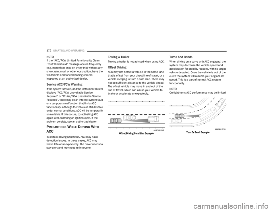
Offset Driving
ACC may not detect a vehicle in the same lane
that is offset from your direct line of travel, or a
vehicle merging in from a side lane. There may
not be sufficient distance to the vehicle ahead.
The offset vehicle may move in and out of the
line of travel, which can cause your vehicle to
brake or accelerate unexpectedly.
Offset Driving Condition Example
Turns And Bends
When driving on a curve with ACC engaged, the
system may decrease the vehicle speed and
acceleration for stability reasons, with no target
vehicle detected. Once the vehicle is out of the
curve the system will resume your original set
speed. This is a part of normal ACC system
functionality.
NOTE:
On tight turns ACC performance may be limited.
Turn Or Bend Example
20_LX_OM_EN_USC_t.book Page 172
Page 175 of 328

STARTING AND OPERATING173
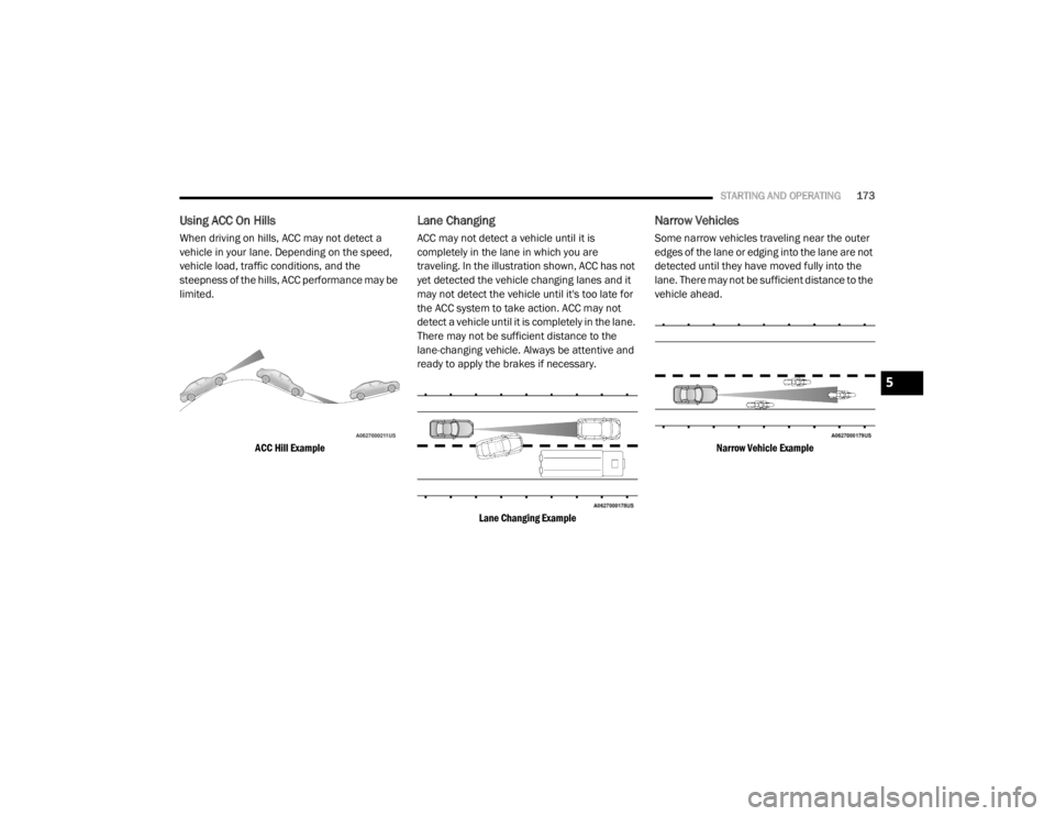
Using ACC On Hills
When driving on hills, ACC may not detect a
vehicle in your lane. Depending on the speed,
vehicle load, traffic conditions, and the
steepness of the hills, ACC performance may be
limited.
ACC Hill Example
Lane Changing
ACC may not detect a vehicle until it is
completely in the lane in which you are
traveling. In the illustration shown, ACC has not
yet detected the vehicle changing lanes and it
may not detect the vehicle until it's too late for
the ACC system to take action. ACC may not
detect a vehicle until it is completely in the lane.
There may not be sufficient distance to the
lane-changing vehicle. Always be attentive and
ready to apply the brakes if necessary.
Lane Changing Example
Narrow Vehicles
Some narrow vehicles traveling near the outer
edges of the lane or edging into the lane are not
detected until they have moved fully into the
lane. There may not be sufficient distance to the
vehicle ahead.
Narrow Vehicle Example
5
20_LX_OM_EN_USC_t.book Page 173
Page 176 of 328

174STARTING AND OPERATING
Stationary Objects And Vehicles
ACC does not react to stationary objects and
stationary vehicles. For example, ACC will not
react in situations where the vehicle you are
following exits your lane and the vehicle ahead
is stopped in your lane. Always be attentive and
ready to apply the brakes if necessary.
Stationary Object And Stationary Vehicle Example
GENERAL INFORMATION
The following regulatory statement applies to all
Radio Frequency (RF) devices equipped in this
vehicle:
This device complies with Part 15 of the FCC
Rules and with Innovation, Science and
Economic Development Canada license-exempt RSS standard(s). Operation is subject to the
following two conditions:
1. This device may not cause harmful
interference, and
2. This device must accept any interference received, including interference that may
cause undesired operation.
Le présent appareil est conforme aux CNR
d`Innovation, Science and Economic
Development applicables aux appareils radio
exempts de licence. L'exploitation est autorisée
aux deux conditions suivantes:
1. l'appareil ne doit pas produire de brouillage, et
2. l'utilisateur de l'appareil doit accepter tout brouillage radioélectrique subi, même si le
brouillage est susceptible d'en compro -
mettre le fonctionnement.
La operación de este equipo está sujeta a las
siguientes dos condiciones:
1. es posible que este equipo o dispositivo no cause interferencia perjudicial y
2. este equipo o dispositivo debe aceptar
cualquier interferencia, incluyendo la que
pueda causar su operación no deseada.
NOTE:
Changes or modifications not expressly
approved by the party responsible for compli -
ance could void the user’s authority to operate
the equipment.
NORMAL (FIXED SPEED) CRUISE
C
ONTROL MODE
In addition to Adaptive Cruise Control mode, a
Normal (Fixed Speed) Cruise Control mode is
available for cruising at fixed speeds. The
Normal (Fixed Speed) Cruise Control mode is
designed to maintain a set cruising speed
without requiring the driver to operate the
accelerator. Cruise Control can only be
operated if the vehicle speed is above
20 mph (32 km/h).
To change between the different control modes,
push the Adaptive Cruise Control (ACC) on/off
button which turns the ACC and the Normal
(Fixed Speed) Cruise Control off. Pushing the
Normal (Fixed Speed) Cruise Control on/off
button will result in turning on (changing to) the
Normal (Fixed Speed) Cruise Control mode.
20_LX_OM_EN_USC_t.book Page 174
Page 178 of 328

176STARTING AND OPERATING
If the button is continually pushed, the set
speed will continue to decrease in 5 mph
decrements until the button is released. The
decrease in set speed is reflected in the
instrument cluster display.
Metric Speed (km/h)
Pushing the SET (-) button once will result in
a 1 km/h decrease in set speed. Each subse -
quent tap of the button results in a decrease
of 1 km/h.
If the button is continually pushed, the set
speed will continue to decrease in 10 km/h
decrements until the button is released. The
decrease in set speed is reflected in the
instrument cluster display.
To Cancel
The following conditions will cancel the Normal
(Fixed Speed) Cruise Control without clearing
the memory:
The brake pedal is applied.
The CANC button is pushed.
The Electronic Stability Control/Traction
Control System (ESC/TCS) activates.
The vehicle parking brake is applied.
The braking temperature exceeds normal
range (overheated).
The gear selector is removed from the DRIVE
position.
To Resume Speed
To resume a previously set speed, push the RES
button and release. Resume can be used at any
speed above 20 mph (32 km/h).
To Turn Off
The system will turn off and erase the set speed
in memory if:
The Normal (Fixed Speed) Cruise Control on/
off button is pushed.
The ignition is placed in the OFF position.
The Adaptive Cruise Control (ACC) on/off
button is pushed.
20_LX_OM_EN_USC_t.book Page 176
Page 183 of 328

STARTING AND OPERATING181
NOTE:
ParkSense will reduce the volume of the radio,
if on, when the system is sounding an audio
tone.
Front Park Assist Audible Alerts
ParkSense will turn off the Front Park Assist
audible alert (chime) after approximately three
seconds when an obstacle has been detected,
the vehicle is stationary, and brake pedal is
applied. Adjustable Chime Volume Settings
Front and Rear chime volume settings can be
selected from the Customer Programmable
Features section of the Uconnect system, refer
to “Uconnect Settings” in “Multimedia” for
further information.
If the Uconnect system is equipped, chime
volume settings will not be accessible from the
instrument cluster display.
The chime volume settings include low,
medium, and high. The factory default volume
setting is medium.
ParkSense will retain its last known
configuration state through ignition cycles.ENABLING AND DISABLING PARKSENSE
ParkSense can be enabled and disabled with
the ParkSense switch, located on the switch
panel below the Uconnect display.
When the ParkSense switch is pushed
to disable the system, the instrument
cluster will display the “PARKSENSE
OFF” message for approximately five
seconds. Refer to “Instrument Cluster Display”
in “Getting To Know Your Instrument Panel” for
further information. When the gear selector is
moved to REVERSE and the system is disabled,
the instrument cluster display will show the
“PARKSENSE OFF” message for as long as the
vehicle is in REVERSE.
WARNING ALERTS FOR FRONT
Front Distance (inches/cm) Greater than 47 inches
(120 cm) 47-39 inches
(120-100 cm) 39-25 inches
(100-65 cm) 25-12 inches
(65-30 cm) Less than 12 inches
(30 cm)
Arcs — Left NoneNone None3rd Flashing 4th Flashing
Arcs — Center None1st Solid 2nd Flashing 3rd Flashing4th Flashing
Arcs — Right NoneNone None3rd Flashing 4th Flashing
Audible Alert Chime NoneNone None FastContinuous
Radio Volume Reduced No
No NoYesYes
5
20_LX_OM_EN_USC_t.book Page 181
Page 188 of 328

186STARTING AND OPERATING
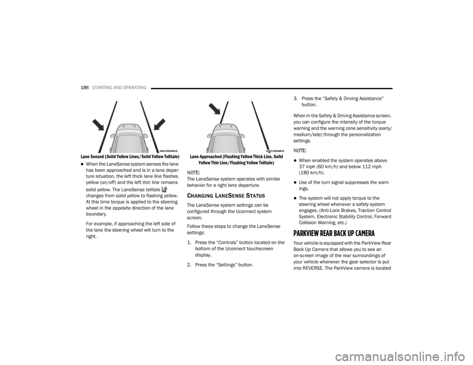
Lane Sensed (Solid Yellow Lines/Solid Yellow Telltale)
When the LaneSense system senses the lane
has been approached and is in a lane depar -
ture situation, the left thick lane line flashes
yellow (on/off) and the left thin line remains
solid yellow. The LaneSense telltale
changes from solid yellow to flashing yellow.
At this time torque is applied to the steering
wheel in the opposite direction of the lane
boundary.
For example, if approaching the left side of
the lane the steering wheel will turn to the
right.
Lane Approached (Flashing Yellow Thick Line, Solid
Yellow Thin Line/Flashing Yellow Telltale)
NOTE:
The LaneSense system operates with similar
behavior for a right lane departure.
CHANGING LANESENSE STATUS
The LaneSense system settings can be
configured through the Uconnect system
screen.
Follow these steps to change the LaneSense
settings:
1. Press the “Controls” button located on the bottom of the Uconnect touchscreen
display.
2. Press the “Settings” button. 3. Press the “Safety & Driving Assistance”
button.
When in the Safety & Driving Assistance screen,
you can configure the intensity of the torque
warning and the warning zone sensitivity (early/
medium/late) through the personalization
settings.
NOTE:
When enabled the system operates above
37 mph (60 km/h) and below 112 mph (180 km/h).
Use of the turn signal suppresses the warn -
ings.
The system will not apply torque to the
steering wheel whenever a safety system
engages. (Anti-Lock Brakes, Traction Control
System, Electronic Stability Control, Forward
Collision Warning, etc.)
PARKVIEW REAR BACK UP CAMERA
Your vehicle is equipped with the ParkView Rear
Back Up Camera that allows you to see an
on-screen image of the rear surroundings of
your vehicle whenever the gear selector is put
into REVERSE. The ParkView camera is located
20_LX_OM_EN_USC_t.book Page 186
Page 193 of 328

STARTING AND OPERATING191
have exceeded either GAWR, but the total load
is within the specified GVWR, you must
redistribute the weight. Improper weight
distribution can have an adverse effect on the
way your vehicle steers and handles and the
way the brakes operate.
NOTE:
Refer to the “Vehicle Certification Label”
affixed to the rear of the driver's door for your
vehicle's GVWR and GAWRs.
Refer to the “Tire Placard” for your vehicle's
proper tire pressure.
TRAILER TOWING
In this section you will find safety tips and
information on limits to the type of towing you
can reasonably do with your vehicle. Before
towing a trailer, carefully review this information
to tow your load as efficiently and safely as
possible.
To maintain the New Vehicle Limited Warranty
coverage, follow the requirements and
recommendations in this manual concerning
vehicles used for trailer towing.
COMMON TOWING DEFINITIONS
The following trailer towing related definitions
will assist you in understanding the following
information:
Gross Vehicle Weight Rating (GVWR)
The GVWR is the total allowable weight of your
vehicle. This includes driver, passengers, cargo
and tongue weight. The total load must be
limited so that you do not exceed the GVWR.
Refer to “Loading” in “Starting And Operating”
for further information.
Gross Trailer Weight (GTW)
The GTW is the weight of the trailer plus the
weight of all cargo, consumables, and
equipment (permanent or temporary) loaded in
or on the trailer in its "loaded and ready for
operation" condition.
The recommended way to measure GTW is to
put your fully loaded trailer on a vehicle scale.
The entire weight of the trailer must be
supported by the scale.
Gross Combination Weight Rating (GCWR)
The GCWR is the total allowable weight of your
vehicle and trailer when weighed in
combination.
Gross Axle Weight Rating (GAWR)
The GAWR is the maximum capacity of the front
and rear axles. Distribute the load over the front
and rear axles evenly. Make sure that you do
not exceed either front or rear GAWR. Refer to
“Loading” in “Starting And Operating” for
further information.
WARNING!
It is important that you do not exceed the
maximum front or rear GAWR. A dangerous
driving condition can result if either rating is
exceeded. You could lose control of the
vehicle and have a collision.
5
20_LX_OM_EN_USC_t.book Page 191