2020 CHRYSLER 300 towing
[x] Cancel search: towingPage 105 of 328

SAFETY103
The BSM system detection zone DOES NOT
change if your vehicle is towing a trailer.
Therefore, visually verify the adjacent lane is
clear for both your vehicle and trailer before
making a lane change. If the trailer or other
object (i.e., bicycle, sports equipment)
extends beyond the side of your vehicle, this
may result in the BSM warning light randomly
alerting on the trailer or even remaining illu -
minated the entire time the vehicle is in a
forward gear.
The Blind Spot Monitoring (BSM) system may
experience drop outs (blinking on and off) of
the side mirror Warning Indicator lamps
when a motorcycle or any small object
remains at the side of the vehicle for
extended periods of time (more than a couple
of seconds).
The area on the rear fascia where the radar
sensors are located must remain free of snow,
ice, and dirt/road contamination so that the
BSM system can function properly. Do not block
the area of the rear fascia where the radar
sensors are located with foreign objects
(bumper stickers, bicycle racks, etc.).
Sensor Location (Driver Side Shown)
The BSM system notifies the driver of objects in
the detection zones by illuminating the BSM
warning light located in the outside mirrors in
addition to sounding an audible (chime) alert
and reducing the radio volume if the
corresponding turn signal is activated. Refer to
“Modes Of Operation” for further information.
The BSM system monitors the detection zone
from three different entry points (side, rear,
front) while driving to see if an alert is
necessary. The BSM system will issue an alert
during these types of zone entries.
Entering From The Side
Vehicles that move into your adjacent lanes
from either side of the vehicle.
Side Monitoring
Entering From The Rear
Vehicles that come up from behind your vehicle
on either side and enter the rear detection zone
with a relative speed of less than 31 mph
(50 km/h).
Rear Monitoring
4
20_LX_OM_EN_USC_t.book Page 103
Page 159 of 328

STARTING AND OPERATING157
DRIVE (D)
This range should be used for most city and
highway driving. It provides the smoothest
upshifts and downshifts, and the best fuel
economy. The transmission automatically
upshifts through all forward gears. The DRIVE
position provides optimum driving characteristics
under all normal operating conditions.
When frequent transmission shifting occurs
(such as when operating the vehicle under
heavy loading conditions, in hilly terrain,
traveling into strong head winds, or while towing
a heavy trailer), use the AutoStick shift control
(if equipped, refer to “AutoStick” in this section
for further information) to select a lower gear.
Under these conditions, using a lower gear will improve performance and extend transmission
life by reducing excessive shifting and heat
buildup.
During extremely cold temperatures (-22°F
[-30°C] or below), transmission operation may
be modified depending on engine and
transmission temperature as well as vehicle
speed. Normal operation will resume once the
transmission temperature has risen to a
suitable level.
SPORT (S) — If Equipped
This mode alters the transmission's automatic
shift schedule for sportier driving. Upshift
speeds are increased to make full use of
available engine power.
To access SPORT mode, push down on the gear
selector and rotate it fully clockwise, or push the
SPORT button in the center stack.
LOW (L) — If Equipped
Use this range for engine braking when
descending very steep grades. In this range, the
transmission will downshift for increased
engine braking. To access the LOW position,
push down on the gear selector and rotate it
fully clockwise.
Transmission Limp Home Mode
Transmission function is monitored
electronically for abnormal conditions. If a
condition is detected that could result in
transmission damage, Transmission Limp
Home Mode is activated. In this mode, the
transmission may operate only in certain gears,
or may not shift at all. Vehicle performance may
be severely degraded and the engine may stall.
In some situations, the transmission may not
re-engage if the engine is turned off and
restarted. The Malfunction Indicator Light (MIL)
may be illuminated. A message in the
instrument cluster will inform the driver of the
more serious conditions, and indicate what
actions may be necessary.
In the event of a momentary problem, the
transmission can be reset to regain all forward
gears by performing the following steps:
NOTE:
In cases where the instrument cluster message
indicates the transmission may not re-engage
after engine shutdown, perform this procedure
only in a desired location (preferably, at an
authorized dealer).CAUTION!
Towing the vehicle, coasting, or driving for any
other reason with the transmission in NEUTRAL
can cause severe transmission damage.
Refer to “Recreational Towing” in “Starting
And Operating” and “Towing A Disabled
Vehicle” in “In Case Of Emergency” for further
information.
5
20_LX_OM_EN_USC_t.book Page 157
Page 160 of 328

158STARTING AND OPERATING
1. Stop the vehicle.
2. Shift the transmission into PARK, if
possible. If not, shift the transmission to
NEUTRAL.
3. Push and hold the ignition switch until the engine turns off.
4. Wait approximately 30 seconds.
5. Restart the engine.
6. Shift into the desired gear range. If the problem is no longer detected, the
transmission will return to normal operation.
NOTE:
Even if the transmission can be reset, we
recommend that you visit an authorized dealer
at your earliest possible convenience. An autho -
rized dealer has diagnostic equipment to
assess the condition of your transmission.
If the transmission cannot be reset, authorized
dealer service is required.
AutoStick — If Equipped
AutoStick is a driver-interactive transmission
feature providing manual shift control, giving
you more control of the vehicle. AutoStick allows you to maximize engine braking,
eliminate undesirable upshifts and downshifts,
and improve overall vehicle performance.
This system can also provide you with more
control during passing, city driving, cold slippery
conditions, mountain driving, trailer towing, and
many other situations.
Operation
When the transmission is in DRIVE or SPORT
mode, it will operate automatically, shifting
between the eight available gears. To engage
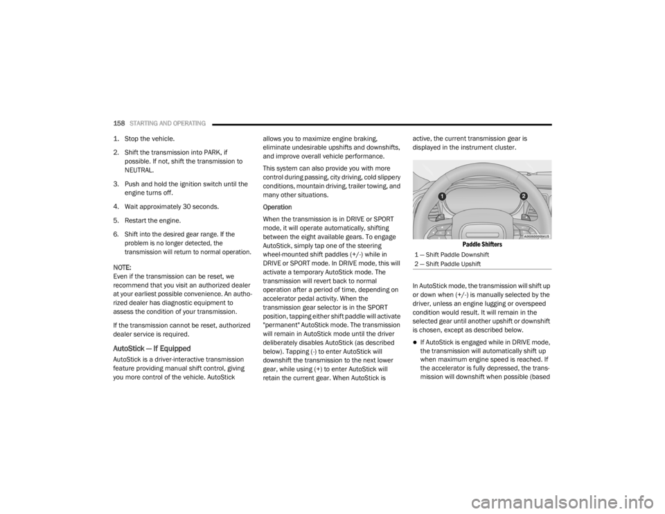
AutoStick, simply tap one of the steering
wheel-mounted shift paddles (+/-) while in
DRIVE or SPORT mode. In DRIVE mode, this will
activate a temporary AutoStick mode. The
transmission will revert back to normal
operation after a period of time, depending on
accelerator pedal activity. When the
transmission gear selector is in the SPORT
position, tapping either shift paddle will activate
"permanent" AutoStick mode. The transmission
will remain in AutoStick mode until the driver
deliberately disables AutoStick (as described
below). Tapping (-) to enter AutoStick will
downshift the transmission to the next lower
gear, while using (+) to enter AutoStick will
retain the current gear. When AutoStick is active, the current transmission gear is
displayed in the instrument cluster.
Paddle Shifters
In AutoStick mode, the transmission will shift up
or down when (+/-) is manually selected by the
driver, unless an engine lugging or overspeed
condition would result. It will remain in the
selected gear until another upshift or downshift
is chosen, except as described below.
If AutoStick is engaged while in DRIVE mode,
the transmission will automatically shift up
when maximum engine speed is reached. If
the accelerator is fully depressed, the trans -
mission will downshift when possible (based
1 — Shift Paddle Downshift
2 — Shift Paddle Upshift
20_LX_OM_EN_USC_t.book Page 158
Page 166 of 328

164STARTING AND OPERATING
(Continued)
ADAPTIVE CRUISE CONTROL (ACC)
O
PERATION
The Speed Control buttons (located on the right
side of the steering wheel) operate the Adaptive
Cruise Control (ACC) system.
Adaptive Cruise Control Buttons
NOTE:
Any chassis/suspension or tire size modifica -
tions to the vehicle will affect the performance
of the Adaptive Cruise Control and Forward
Collision Warning system.
The ACC system:
Does not react to pedestrians,
oncoming vehicles, and stationary
objects (e.g., a stopped vehicle in a
traffic jam or a disabled vehicle).
Cannot take street, traffic, and weather
conditions into account, and may be
limited upon adverse sight distance
conditions.
Does not always fully recognize
complex driving conditions, which can
result in wrong or missing distance
warnings.
Will bring the vehicle to a complete stop
while following a target vehicle and hold
the vehicle for two seconds in the stop
position. If the target vehicle does not
start moving within two seconds the
ACC system will display a message that
the system will release the brakes and
that the brakes must be applied manu -
ally. An audible chime will sound when
the brakes are released.
WARNING! (Continued)
You should switch off the ACC system:
When driving in fog, heavy rain, heavy
snow, sleet, heavy traffic, and complex
driving situations (i.e., in highway construc -
tion zones).
When entering a turn lane or highway off
ramp; when driving on roads that are
winding, icy, snow-covered, slippery, or
have steep uphill or downhill slopes.
When towing a trailer up or down steep
slopes.
When circumstances do not allow safe
driving at a constant speed.
WARNING! (Continued)
1 — CANC/Cancel
2 — Normal (Fixed Speed) Cruise Control On/Off
3 — Adaptive Cruise Control (ACC) On/Off
4 — Distance Setting Decrease
5 — SET (+)/Accelerate
6 — RES/Resume
7 — SET (-)/Decelerate
8 — Distance Setting Increase
20_LX_OM_EN_USC_t.book Page 164
Page 174 of 328

172STARTING AND OPERATING
NOTE:
If the “ACC/FCW Limited Functionality Clean
Front Windshield” message occurs frequently
(e.g. more than once on every trip) without any
snow, rain, mud, or other obstruction, have the
windshield and forward facing camera
inspected at an authorized dealer.
Service ACC/FCW Warning
If the system turns off, and the instrument cluster
displays “ACC/FCW Unavailable Service
Required” or “Cruise/FCW Unavailable Service
Required”, there may be an internal system fault
or a temporary malfunction that limits ACC
functionality. Although the vehicle is still drivable
under normal conditions, ACC will be temporarily
unavailable. If this occurs, try activating ACC
again later, following an ignition cycle. If the
problem persists, see an authorized dealer.
PRECAUTIONS WHILE DRIVING WITH
ACC
In certain driving situations, ACC may have
detection issues. In these cases, ACC may
brake late or unexpectedly. The driver needs to
stay alert and may need to intervene.
Towing A Trailer
Towing a trailer is not advised when using ACC.
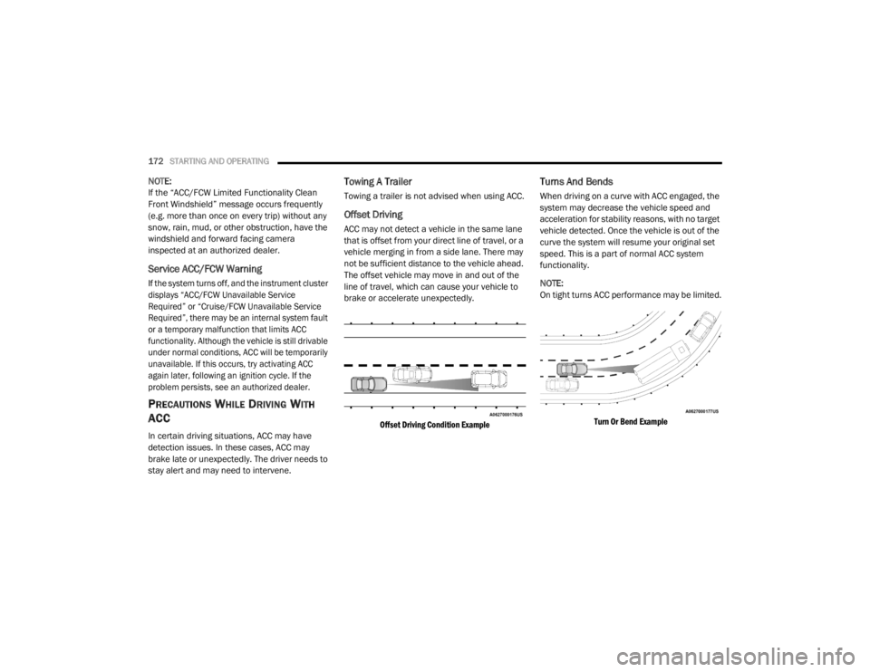
Offset Driving
ACC may not detect a vehicle in the same lane
that is offset from your direct line of travel, or a
vehicle merging in from a side lane. There may
not be sufficient distance to the vehicle ahead.
The offset vehicle may move in and out of the
line of travel, which can cause your vehicle to
brake or accelerate unexpectedly.
Offset Driving Condition Example
Turns And Bends
When driving on a curve with ACC engaged, the
system may decrease the vehicle speed and
acceleration for stability reasons, with no target
vehicle detected. Once the vehicle is out of the
curve the system will resume your original set
speed. This is a part of normal ACC system
functionality.
NOTE:
On tight turns ACC performance may be limited.
Turn Or Bend Example
20_LX_OM_EN_USC_t.book Page 172
Page 185 of 328

STARTING AND OPERATING183
ParkSense, when on, will reduce the volume
of the radio when it is sounding a tone.
Clean the ParkSense sensors regularly,
taking care not to scratch or damage them.
The sensors must not be covered with ice,
snow, slush, mud, dirt or debris. Failure to do
so can result in the system not working prop -
erly. The ParkSense system might not detect
an obstacle behind or in front of the fascia/
bumper, or it could provide a false indication
that an obstacle is behind or in front of the
fascia/bumper.
Use the ParkSense switch to turn the Park -
Sense system off if objects such as bicycle
carriers, trailer hitches, etc. are placed within
12 inches (30 cm) from the rear fascia/
bumper. Failure to do so can result in the
system misinterpreting a close object as a
sensor problem, causing the “PARKSENSE
UNAVAILABLE SERVICE REQUIRED” message
to be displayed in the instrument cluster.
LANESENSE — IF EQUIPPED
LANESENSE OPERATION
The LaneSense system is operational at speeds
above 37 mph (60 km/h) and below 112 mph
(180 km/h). The LaneSense system uses a
forward looking camera to detect lane markings
and measure vehicle position within the lane
boundaries.
When both lane markings are detected and the
driver drifts out of the lane (no turn signal
applied), the LaneSense system provides a
WARNING!
Drivers must be careful when backing up
even when using ParkSense. Always check
carefully behind your vehicle, look behind
you, and be sure to check for pedestrians,
animals, other vehicles, obstructions, and
blind spots before backing up. You are
responsible for safety and must continue to
pay attention to your surroundings. Failure
to do so can result in serious injury or
death.
Before using ParkSense, it is strongly
recommended that the ball mount and
hitch ball assembly is disconnected from
the vehicle when the vehicle is not used for
towing. Failure to do so can result in injury
or damage to vehicles or obstacles
because the hitch ball will be much closer
to the obstacle than the rear fascia when
the loudspeaker sounds the continuous
tone. Also, the sensors could detect the ball
mount and hitch ball assembly, depending
on its size and shape, giving a false indica -
tion that an obstacle is behind the vehicle.
CAUTION!
ParkSense is only a parking aid and it is
unable to recognize every obstacle,
including small obstacles. Parking curbs
might be temporarily detected or not
detected at all. Obstacles located above or
below the sensors will not be detected
when they are in close proximity.
The vehicle must be driven slowly when
using ParkSense in order to be able to stop
in time when an obstacle is detected. It is
recommended that the driver looks over
his/her shoulder when using ParkSense.
5
20_LX_OM_EN_USC_t.book Page 183
Page 193 of 328

STARTING AND OPERATING191
have exceeded either GAWR, but the total load
is within the specified GVWR, you must
redistribute the weight. Improper weight
distribution can have an adverse effect on the
way your vehicle steers and handles and the
way the brakes operate.
NOTE:
Refer to the “Vehicle Certification Label”
affixed to the rear of the driver's door for your
vehicle's GVWR and GAWRs.
Refer to the “Tire Placard” for your vehicle's
proper tire pressure.
TRAILER TOWING
In this section you will find safety tips and
information on limits to the type of towing you
can reasonably do with your vehicle. Before
towing a trailer, carefully review this information
to tow your load as efficiently and safely as
possible.
To maintain the New Vehicle Limited Warranty
coverage, follow the requirements and
recommendations in this manual concerning
vehicles used for trailer towing.
COMMON TOWING DEFINITIONS
The following trailer towing related definitions
will assist you in understanding the following
information:
Gross Vehicle Weight Rating (GVWR)
The GVWR is the total allowable weight of your
vehicle. This includes driver, passengers, cargo
and tongue weight. The total load must be
limited so that you do not exceed the GVWR.
Refer to “Loading” in “Starting And Operating”
for further information.
Gross Trailer Weight (GTW)
The GTW is the weight of the trailer plus the
weight of all cargo, consumables, and
equipment (permanent or temporary) loaded in
or on the trailer in its "loaded and ready for
operation" condition.
The recommended way to measure GTW is to
put your fully loaded trailer on a vehicle scale.
The entire weight of the trailer must be
supported by the scale.
Gross Combination Weight Rating (GCWR)
The GCWR is the total allowable weight of your
vehicle and trailer when weighed in
combination.
Gross Axle Weight Rating (GAWR)
The GAWR is the maximum capacity of the front
and rear axles. Distribute the load over the front
and rear axles evenly. Make sure that you do
not exceed either front or rear GAWR. Refer to
“Loading” in “Starting And Operating” for
further information.
WARNING!
It is important that you do not exceed the
maximum front or rear GAWR. A dangerous
driving condition can result if either rating is
exceeded. You could lose control of the
vehicle and have a collision.
5
20_LX_OM_EN_USC_t.book Page 191
Page 194 of 328

192STARTING AND OPERATING
Tongue Weight (TW)
The tongue weight is the downward force
exerted on the hitch ball by the trailer. You must
consider this as part of the load on your vehicle.
Trailer Frontal Area
The frontal area is the maximum height
multiplied by the maximum width of the front of
a trailer.
Trailer Sway Control
The Trailer Sway Control (TSC) can be a
mechanical telescoping link that can be
installed between the hitch receiver and the
trailer tongue that typically provides adjustable
friction associated with the telescoping motion
to dampen any unwanted trailer swaying
motions while traveling.
If equipped, the electronic TSC recognizes a
swaying trailer and automatically applies
individual wheel brakes and/or reduces engine
power to attempt to eliminate the trailer sway.
Weight-Carrying Hitch
A weight-carrying hitch supports the trailer
tongue weight, just as if it were luggage located
at a hitch ball or some other connecting point of
the vehicle. These kinds of hitches are the most
popular on the market today and they are
commonly used to tow small and medium sized
trailers.
Weight-Distributing Hitch
A weight-distributing system works by applying
leverage through spring (load) bars. They are
typically used for heavier loads to distribute
trailer tongue weight to the tow vehicle's front
axle and the trailer axle(s). When used in
accordance with the manufacturer's directions,
it provides for a more level ride, offering more
consistent steering and brake control thereby
enhancing towing safety. The addition of a
friction/hydraulic sway control also dampens
sway caused by traffic and crosswinds and
contributes positively to tow vehicle and trailer stability. Trailer sway control and a weight
distributing (load equalizing) hitch are
recommended for heavier Tongue Weights (TW)
and may be required depending on vehicle and
trailer configuration/loading to comply with
Gross Axle Weight Rating (GAWR) requirements.
WARNING!
An improperly adjusted Weight Distributing
Hitch system may reduce handling,
stability, braking performance, and could
result in a collision.
Weight Distributing Systems may not be
compatible with Surge Brake Couplers.
Consult with your hitch and trailer manufac
-
turer or a reputable Recreational Vehicle
dealer for additional information.
20_LX_OM_EN_USC_t.book Page 192