2020 CHRYSLER 300 alarm
[x] Cancel search: alarmPage 68 of 328

66GETTING TO KNOW YOUR VEHICLE
GARAGE DOOR OPENER — IF EQUIPPED
HomeLink® replaces up to three hand-held
transmitters that operate devices such as
garage door openers, motorized gates, lighting
or home security systems. The HomeLink® unit
is powered by your vehicle’s battery.
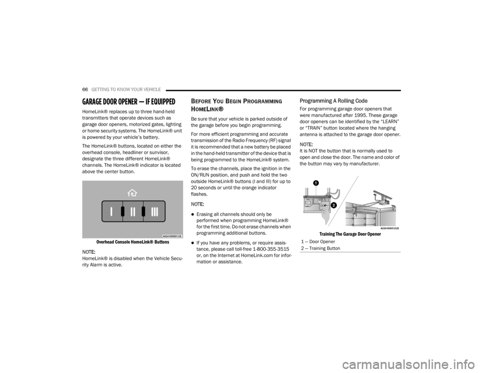
The HomeLink® buttons, located on either the
overhead console, headliner or sunvisor,
designate the three different HomeLink®
channels. The HomeLink® indicator is located
above the center button.
Overhead Console HomeLink® Buttons
NOTE:
HomeLink® is disabled when the Vehicle Secu -
rity Alarm is active.
BEFORE YOU BEGIN PROGRAMMING
H
OMELINK®
Be sure that your vehicle is parked outside of
the garage before you begin programming.
For more efficient programming and accurate
transmission of the Radio Frequency (RF) signal
it is recommended that a new battery be placed
in the hand-held transmitter of the device that is
being programmed to the HomeLink® system.
To erase the channels, place the ignition in the
ON/RUN position, and push and hold the two
outside HomeLink® buttons (I and III) for up to
20 seconds or until the orange indicator
flashes.
NOTE:
Erasing all channels should only be
performed when programming HomeLink®
for the first time. Do not erase channels when
programming additional buttons.
If you have any problems, or require assis -
tance, please call toll-free 1-800-355-3515
or, on the Internet at HomeLink.com for infor -
mation or assistance.
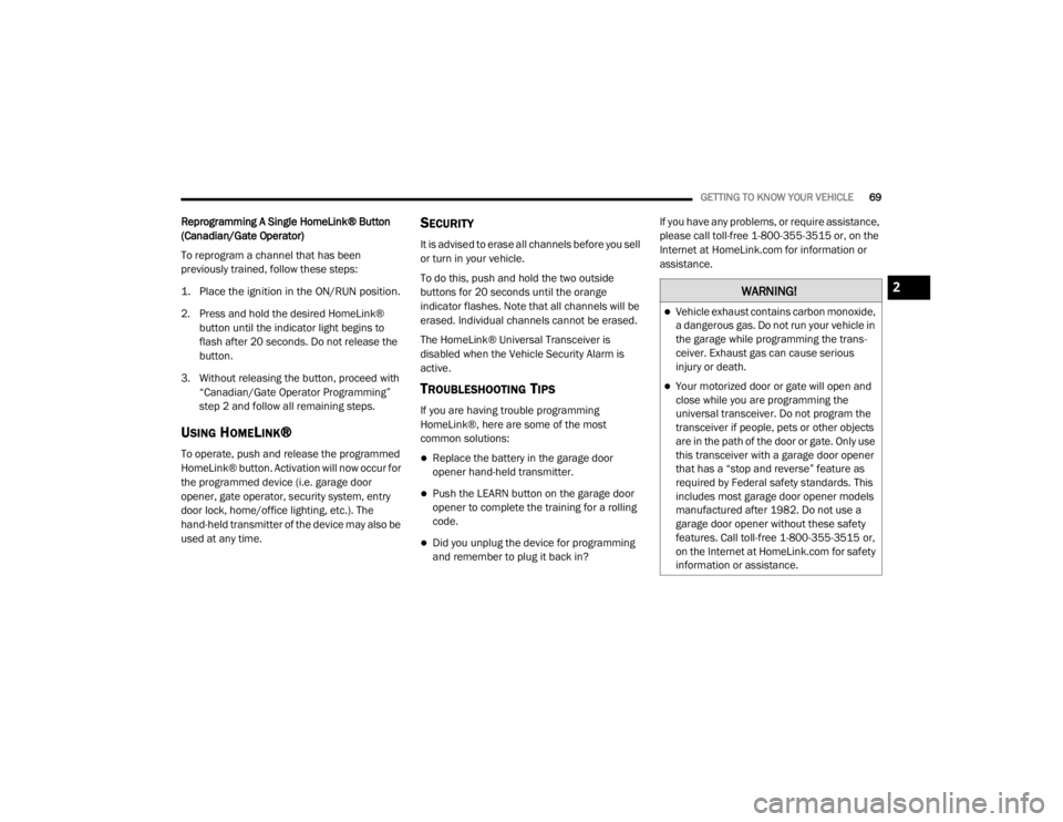
Programming A Rolling Code
For programming garage door openers that
were manufactured after 1995. These garage
door openers can be identified by the “LEARN”
or “TRAIN” button located where the hanging
antenna is attached to the garage door opener.
NOTE:
It is NOT the button that is normally used to
open and close the door. The name and color of
the button may vary by manufacturer.
Training The Garage Door Opener
1 — Door Opener
2 — Training Button
20_LX_OM_EN_USC_t.book Page 66
Page 71 of 328

GETTING TO KNOW YOUR VEHICLE69
Reprogramming A Single HomeLink® Button
(Canadian/Gate Operator)
To reprogram a channel that has been
previously trained, follow these steps:
1. Place the ignition in the ON/RUN position.
2. Press and hold the desired HomeLink®
button until the indicator light begins to
flash after 20 seconds. Do not release the
button.
3. Without releasing the button, proceed with “Canadian/Gate Operator Programming”
step 2 and follow all remaining steps.
USING HOMELINK®
To operate, push and release the programmed
HomeLink® button. Activation will now occur for
the programmed device (i.e. garage door
opener, gate operator, security system, entry
door lock, home/office lighting, etc.). The
hand-held transmitter of the device may also be
used at any time.
SECURITY
It is advised to erase all channels before you sell
or turn in your vehicle.
To do this, push and hold the two outside
buttons for 20 seconds until the orange
indicator flashes. Note that all channels will be
erased. Individual channels cannot be erased.
The HomeLink® Universal Transceiver is
disabled when the Vehicle Security Alarm is
active.
TROUBLESHOOTING TIPS
If you are having trouble programming
HomeLink®, here are some of the most
common solutions:
Replace the battery in the garage door
opener hand-held transmitter.
Push the LEARN button on the garage door
opener to complete the training for a rolling
code.
Did you unplug the device for programming
and remember to plug it back in? If you have any problems, or require assistance,
please call toll-free 1-800-355-3515 or, on the
Internet at HomeLink.com for information or
assistance.
WARNING!
Vehicle exhaust contains carbon monoxide,
a dangerous gas. Do not run your vehicle in
the garage while programming the trans -
ceiver. Exhaust gas can cause serious
injury or death.
Your motorized door or gate will open and
close while you are programming the
universal transceiver. Do not program the
transceiver if people, pets or other objects
are in the path of the door or gate. Only use
this transceiver with a garage door opener
that has a “stop and reverse” feature as
required by Federal safety standards. This
includes most garage door opener models
manufactured after 1982. Do not use a
garage door opener without these safety
features. Call toll-free 1-800-355-3515 or,
on the Internet at HomeLink.com for safety
information or assistance.
2
20_LX_OM_EN_USC_t.book Page 69
Page 86 of 328

84GETTING TO KNOW YOUR INSTRUMENT PANEL
115 Volts AC Power Inverter System
Audio and Telematics System
Loss of the battery charge may indicate one or
more of the following conditions:
The charging system cannot deliver enough
electrical power to the vehicle system
because the electrical loads are larger than
the capability of the charging system. The
charging system is still functioning properly.
Turning on all possible vehicle electrical
loads (e.g. HVAC to max settings, exterior and
interior lights, overloaded power outlets
+12 Volts, 115 Volts AC, USB ports) during
certain driving conditions (city driving,
towing, frequent stopping).
Installing options like additional lights,
upfitter electrical accessories, audio
systems, alarms and similar devices.
Unusual driving cycles (short trips separated
by long parking periods).
The vehicle was parked for an extended
period of time (weeks, months).
The battery was recently replaced and was
not charged completely.
The battery was discharged by an electrical
load left on when the vehicle was parked.
The battery was used for an extended period
with the engine not running to supply radio,
lights, chargers, +12 Volt portable appli -
ances like vacuum cleaners, game consoles
and similar devices.
What to do when an electrical load reduction
action message is present (“Battery Saver On”
or “Battery Saver Mode”)
During a trip:
Reduce power to unnecessary loads if
possible:
Turn off redundant lights (interior or exte -
rior)
Check what may be plugged in to power
outlets +12 Volts, 115 Volts AC, USB
ports
Check HVAC settings (blower, tempera -
ture)
Check the audio settings (volume)
After a trip:
Check if any aftermarket equipment was
installed (additional lights, upfitter electrical accessories, audio systems, alarms) and
review specifications if any (load and Ignition
Off Draw currents).
Evaluate the latest driving cycles (distance,
driving time and parking time).
The vehicle should have service performed if
the message is still present during consecu
-
tive trips and the evaluation of the vehicle
and driving pattern did not help to identify the
cause.
WARNING LIGHTS AND MESSAGES
The warning/indicator lights will illuminate in
the instrument panel together with a dedicated
message and/or acoustic signal when
applicable. These indications are indicative and
precautionary and as such must not be
considered as exhaustive and/or alternative to
the information contained in the Owner’s
Manual, which you are advised to read carefully
in all cases. Always refer to the information in
this chapter in the event of a failure indication.
All active warning lights will display first if
applicable. The system check menu may
appear different based upon equipment
options and current vehicle status. Some
warning lights are optional and may not appear.
20_LX_OM_EN_USC_t.book Page 84
Page 89 of 328

GETTING TO KNOW YOUR INSTRUMENT PANEL87
Refer to “If Your Engine Overheats” in “In Case
Of Emergency” for further information.
Oil Pressure Warning Light
This warning light will illuminate to
indicate low engine oil pressure. If the
light turns on while driving, stop the
vehicle, shut off the engine as soon as
possible, and contact an authorized dealer. A
chime will sound when this light turns on.
Do not operate the vehicle until the cause is
corrected. This light does not indicate how
much oil is in the engine. The engine oil level
must be checked under the hood.
Oil Temperature Warning Light
This warning light will illuminate to
indicate the engine oil temperature is
high. If the light turns on while driving,
stop the vehicle and shut off the
engine as soon as possible. Wait for oil
temperature to return to normal levels.
Seat Belt Reminder Warning Light
This warning light indicates when the
driver or passenger seat belt is
unbuckled. When the ignition is first
placed in the ON/RUN or ACC/ON/ RUN position and if the driver’s seat belt is
unbuckled, a chime will sound and the light will
turn on. When driving, if the driver or front
passenger seat belt remains unbuckled, the
Seat Belt Reminder Light will flash or remain on
continuously and a chime will sound.
Refer to “Occupant Restraint Systems” in
“Safety” for further information.
Transmission Temperature Warning Light
— If Equipped
This warning light will illuminate to
warn of a high transmission fluid
temperature. This may occur with
strenuous usage such as trailer
towing. If this light turns on, stop the vehicle and
run the engine at idle or slightly faster, with the
transmission in PARK or NEUTRAL, until the
light turns off. Once the light turns off, you may
continue to drive normally.
Trunk Open Warning Light
This indicator will illuminate when the
trunk is open and not fully closed.
NOTE:
If the vehicle is moving, there will also be a
single chime.
Vehicle Security Warning Light — If
Equipped
This light will flash at a fast rate for
approximately 15 seconds when the
vehicle security alarm is arming, and
then will flash slowly until the vehicle
is disarmed.
WARNING!
If you continue operating the vehicle when
the Transmission Temperature Warning Light
is illuminated you could cause the fluid to boil
over, come in contact with hot engine or
exhaust components and cause a fire.
CAUTION!
Continuous driving with the Transmission
Temperature Warning Light illuminated will
eventually cause severe transmission
damage or transmission failure.
3
20_LX_OM_EN_USC_t.book Page 87
Page 107 of 328

SAFETY105
Rear Cross Path (RCP) - If Equipped
The Rear Cross Path (RCP) feature is intended
to aid the driver when backing out of parking
spaces where their vision of oncoming vehicles
may be blocked. Proceed slowly and cautiously
out of the parking space until the rear end of the
vehicle is exposed. The RCP system will then
have a clear view of the cross traffic and if an
oncoming vehicle is detected, alert the driver.
RCP Detection Zones
RCP monitors the rear detection zones on both
sides of the vehicle, for objects that are moving
toward the side of the vehicle with a minimum
speed of approximately 3 mph (5 km/h), to
objects moving a maximum of approximately
20 mph (32 km/h), such as in parking lot
situations. NOTE:
In a parking lot situation, oncoming vehicles can
be obscured by vehicles parked on either side.
If the sensors are blocked by other structures or
vehicles, the system will not be able to alert the
driver.
When RCP is on and the vehicle is in REVERSE,
the driver is alerted using both the visual and
audible alarms, including reducing the radio
volume.
Modes Of Operation
Three selectable modes of operation are
available in the Uconnect System. Refer to
“Uconnect Settings” in “Multimedia” for further
information.
Blind Spot Alert Lights Only
When operating in Blind Spot Alert mode, the
BSM system will provide a visual alert in the
appropriate side view mirror based on a
detected object. However, when the system is
operating in Rear Cross Path (RCP) mode, the
system will respond with both visual and
audible alerts when a detected object is
present. Whenever an audible alert is
requested, the radio is muted.
Blind Spot Alert Lights/Chime
When operating in Blind Spot Alert Lights/
Chime mode, the BSM system will provide a
visual alert in the appropriate side view mirror
based on a detected object. If the turn signal is
then activated, and it corresponds to an alert
present on that side of the vehicle, an audible
chime will also be sounded. Whenever a turn
signal and detected object are present on the
WARNING!
Rear Cross Path Detection (RCP) is not a back
up aid system. It is intended to be used to
help a driver detect an oncoming vehicle in a
parking lot situation. Drivers must be careful
when backing up, even when using RCP.
Always check carefully behind your vehicle,
look behind you, and be sure to check for
pedestrians, animals, other vehicles,
obstructions, and blind spots before backing
up. Failure to do so can result in serious
injury or death.
4
20_LX_OM_EN_USC_t.book Page 105
Page 127 of 328

SAFETY125
Knee Impact Bolsters
The Knee Impact Bolsters help protect the
knees of the driver and front passenger, and
position the front occupants for improved
interaction with the front air bags.
Supplemental Driver Knee Air Bag
This vehicle is equipped with a Supplemental
Driver Knee Air Bag mounted in the instrument
panel below the steering column. The
Supplemental Driver Knee Air Bag provides
enhanced protection during a frontal impact by
working together with the seat belts,
pretensioners, and front air bags.
Supplemental Side Air Bags
Supplemental Seat-Mounted Side Air Bags
(SABs)
This vehicle is equipped with Supplemental
Seat-Mounted Side Air Bags (SABs).
Supplemental Seat-Mounted Side Air Bags
(SABs) are located in the outboard side of the
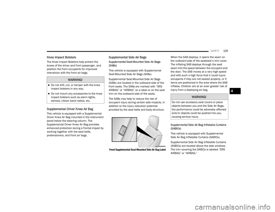
front seats. The SABs are marked with “SRS
AIRBAG” or “AIRBAG” on a label or on the seat
trim on the outboard side of the seats.
The SABs may help to reduce the risk of
occupant injury during certain side impacts, in
addition to the injury reduction potential
provided by the seat belts and body structure.
Front Supplemental Seat-Mounted Side Air Bag Label
When the SAB deploys, it opens the seam on
the outboard side of the seatback’s trim cover.
The inflating SAB deploys through the seat
seam into the space between the occupant and
the door. The SAB moves at a very high speed
and with such a high force that it could injure
occupants if they are not seated properly, or if
items are positioned in the area where the SAB
inflates. Children are at an even greater risk of
injury from a deploying air bag.
Supplemental Side Air Bag Inflatable Curtains
(SABICs)
This vehicle is equipped with Supplemental
Side Air Bag Inflatable Curtains (SABICs).
Supplemental Side Air Bag Inflatable Curtains
(SABICs) are located above the side windows.
The trim covering the SABICs is labeled “SRS
AIRBAG” or “AIRBAG.”
WARNING!
Do not drill, cut, or tamper with the knee
impact bolsters in any way.
Do not mount any accessories to the knee
impact bolsters such as alarm lights,
stereos, citizen band radios, etc.WARNING!
Do not use accessory seat covers or place
objects between you and the Side Air Bags;
the performance could be adversely affected
and/or objects could be pushed into you,
causing serious injury.
4
20_LX_OM_EN_USC_t.book Page 125
Page 177 of 328

STARTING AND OPERATING175
To Set A Desired Speed
Turn the Normal (Fixed Speed) Cruise
Control on. When the vehicle has
reached the desired speed, push the
SET (+) or SET (-) button and release.
Release the accelerator and the vehicle will
operate at the selected speed. Once a speed
has been set a message “CRUISE CONTROL SET
TO MPH (km/h)” will appear indicating what
speed was set. This light will turn on when the
system is turned on via the on/off control. It
turns green when the cruise control is set.
To Vary The Speed Setting
To Increase Speed
When the Normal (Fixed Speed) Cruise Control
is set, you can increase speed by pushing the
SET (+) button.
The driver's preferred units can be selected
through the instrument cluster display. Refer to
“Getting To Know Your Instrument Panel” for
more information. The speed increment shown
is dependent on the speed of U.S. (mph) or
Metric (km/h) units:
U.S. Speed (mph)
Pushing the SET (+) button once will result in
a 1 mph increase in set speed. Each subse -
quent tap of the button results in an increase
of 1 mph.
If the button is continually pushed, the set
speed will continue to increase in 5 mph
increments until the button is released. The
increase in set speed is reflected in the
instrument cluster display. Metric Speed (km/h)
Pushing the SET (+) button once will result in
a 1 km/h increase in set speed. Each subse -
quent tap of the button results in an increase
of 1 km/h.
If the button is continually pushed, the set
speed will continue to increase in 10 km/h
increments until the button is released. The
increase in set speed is reflected in the
instrument cluster display.
To Decrease Speed
When the Normal (Fixed Speed) Cruise Control
is set, you can decrease speed by pushing the
SET (-) button.
The driver's preferred units can be selected
through the instrument cluster display. Refer to
“Getting To Know Your Instrument Panel” for
more information. The speed decrement shown
is dependent on the speed of U.S. (mph) or
Metric (km/h) units:
U.S. Speed (mph)
Pushing the SET (-) button once will result in
a 1 mph decrease in set speed. Each subse -
quent tap of the button results in a decrease
of 1 mph.
WARNING!
In the Normal (Fixed Speed) Cruise Control
mode, the system will not react to vehicles
ahead. In addition, the proximity warning
does not activate and no alarm will sound
even if you are too close to the vehicle ahead
since neither the presence of the vehicle
ahead nor the vehicle-to-vehicle distance is
detected. Be sure to maintain a safe distance
between your vehicle and the vehicle ahead.
Always be aware which mode is selected.
5
20_LX_OM_EN_USC_t.book Page 175
Page 317 of 328

315
INDEX
A
About Your Brakes......................................... 275Adaptive Cruise Control (ACC)
(Cruise Control).............................................. 163Adding Engine Coolant (Antifreeze)............... 248Adding Fuel.................................................... 188Adding Washing Fluid.................................... 238Additives, Fuel............................................... 277AdjustForward....................................................... 31Rearward..................................................... 31Air Bag........................................................... 123Advance Front Air Bag............................... 123Air Bag Operation...................................... 124Air Bag Warning Light................................ 122Driver Knee Air Bag................................... 125Enhanced Accident Response......... 129, 230Event Data Recorder (EDR)....................... 230Front Air Bag............................................. 123If Deployment Occurs................................ 128Knee Impact Bolsters................................ 125Maintaining Your Air Bag System.............. 129Maintenance............................................. 129Redundant Air Bag Warning Light.............123Side Air Bags............................................. 125Transporting Pets...................................... 142
Air Bag Light.................................. 85, 122, 143Air Cleaner, Engine
(Engine Air Cleaner Filter)............................. 241Air Conditioner Maintenance........................ 242Air Conditioner Refrigerant........................... 242Air Conditioner System...........................50, 242Air Conditioning Filter..............................57, 243Air Conditioning, Operating Tips....................... 56Air Filter........................................................ 241Air PressureTires......................................................... 261AlarmArm The System................................... 22, 23Panic........................................................... 13Rearm The System...................................... 23Security Alarm...................................... 22, 87Alarm SystemSecurity Alarm............................................. 22All Wheel DriveTowing...................................................... 229All Wheel Drive (AWD)................................... 253Alterations/ModificationsVehicle........................................................... 9Android Auto................................................. 308Antifreeze (Engine Coolant)................. 248, 280Disposal................................................... 249
Anti-Lock Brake System (ABS)..........................95Anti-Lock Warning Light...................................90Apple CarPlay................................................ 309Arming SystemSecurity Alarm.............................................22Assist, Hill Start............................................. 100Audio Systems (Radio).................................. 284Auto Down Power Windows..............................58Auto Up Power Windows..................................58Automatic Door Locks...............................27, 28Automatic Headlights.......................................44Automatic High Beams.....................................43Automatic Temperature Control (ATC)..............55Automatic Transmission................................ 153Adding Fluid............................ 252, 281, 283Fluid And Filter Change............................. 252Fluid Change............................................. 252Fluid Level Check............................. 251, 252Fluid Type............................... 251, 281, 283Special Additives...................................... 252Automatic Transmission Limp
Home Mode........................................... 27, 157AutostickOperation.................................................. 158AUX Cord....................................................... 302Auxiliary Electrical Outlet (Power Outlet)..........74
11
20_LX_OM_EN_USC_t.book Page 315