2020 CHEVROLET SILVERADO height
[x] Cancel search: heightPage 295 of 495
Chevrolet Silverado Owner Manual (GMNA-Localizing-U.S./Canada/Mexico-
13337620) - 2020 - CTC - 1/27/20
294 Driving and Operating
Vehicle SeriesTrailer WeightWeight-Distributing Hitch
Usage Hitch Distribution
1500 Up to 3 175 kg (7,000 lb) Not Required 50%
1500 Over 3 175 kg (7,000 lb) Required50%
2500/3500 Up to 9 080 kg (20,000 lb) Not Required 25%
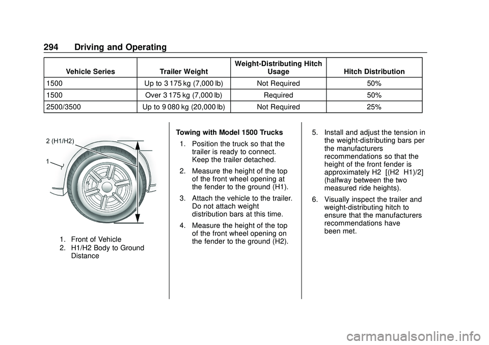
1. Front of Vehicle
2. H1/H2 Body to Ground
Distance
Towing with Model 1500 Trucks
1. Position the truck so that the trailer is ready to connect.
Keep the trailer detached.
2. Measure the height of the top of the front wheel opening at
the fender to the ground (H1).
3. Attach the vehicle to the trailer. Do not attach weight
distribution bars at this time.
4. Measure the height of the top of the front wheel opening on
the fender to the ground (H2). 5. Install and adjust the tension in
the weight-distributing bars per
the manufacturers’
recommendations so that the
height of the front fender is
approximately H2−[(H2−H1)/2]
(halfway between the two
measured ride heights).
6. Visually inspect the trailer and weight-distributing hitch to
ensure that the manufacturers’
recommendations have
been met.
Page 296 of 495
Chevrolet Silverado Owner Manual (GMNA-Localizing-U.S./Canada/Mexico-
13337620) - 2020 - CTC - 1/27/20
Driving and Operating 295
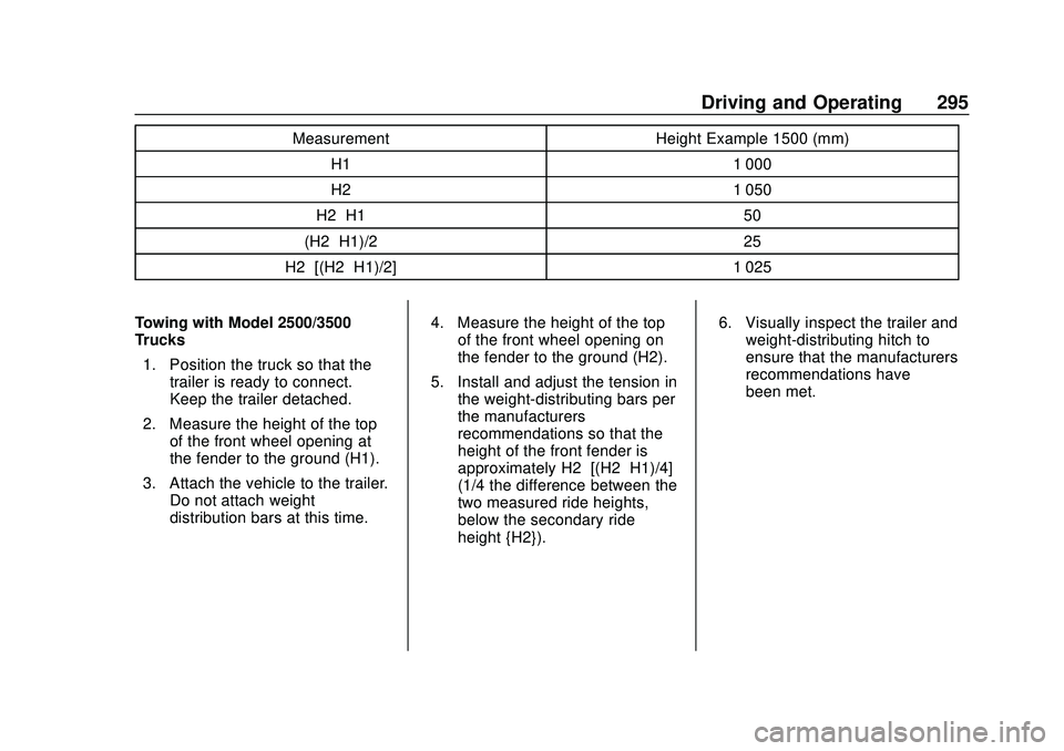
MeasurementHeight Example 1500 (mm)
H1 1 000
H2 1 050
H2−H1 50
(H2−H1)/2 25
H2−[(H2−H1)/2] 1 025
Towing with Model 2500/3500
Trucks 1. Position the truck so that the trailer is ready to connect.
Keep the trailer detached.
2. Measure the height of the top of the front wheel opening at
the fender to the ground (H1).
3. Attach the vehicle to the trailer. Do not attach weight
distribution bars at this time. 4. Measure the height of the top
of the front wheel opening on
the fender to the ground (H2).
5. Install and adjust the tension in the weight-distributing bars per
the manufacturers’
recommendations so that the
height of the front fender is
approximately H2−[(H2−H1)/4]
(1/4 the difference between the
two measured ride heights,
below the secondary ride
height {H2}). 6. Visually inspect the trailer and
weight-distributing hitch to
ensure that the manufacturers’
recommendations have
been met.
Page 297 of 495
Chevrolet Silverado Owner Manual (GMNA-Localizing-U.S./Canada/Mexico-
13337620) - 2020 - CTC - 1/27/20
296 Driving and Operating
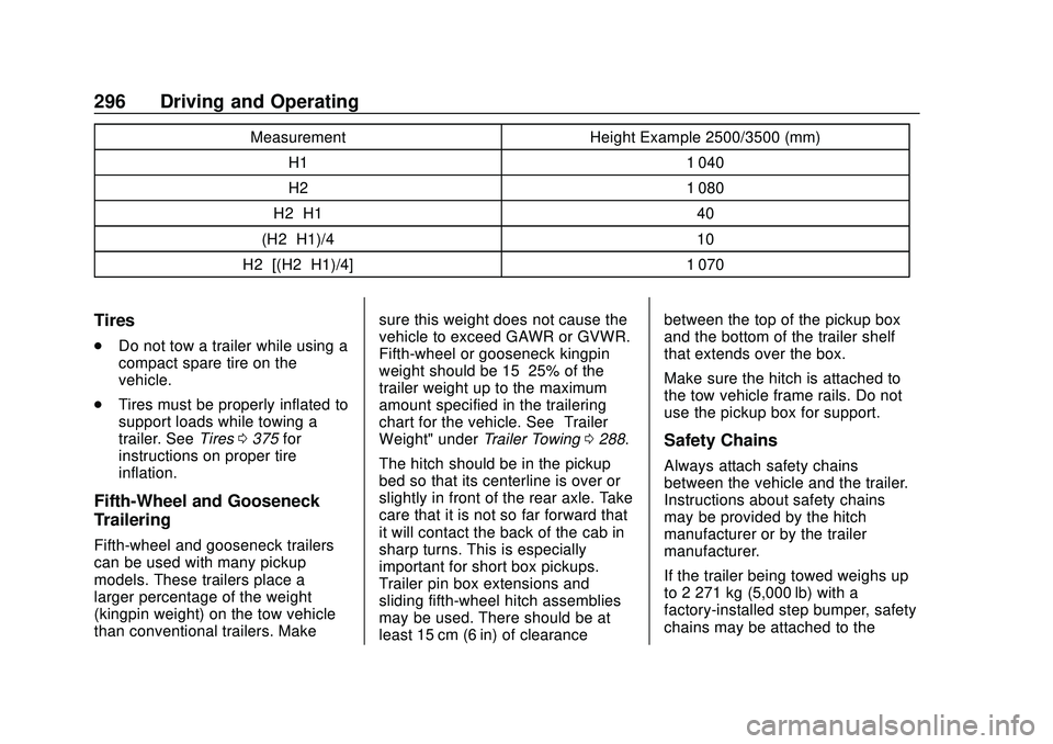
MeasurementHeight Example 2500/3500 (mm)
H1 1 040
H2 1 080
H2−H1 40
(H2−H1)/4 10
H2−[(H2−H1)/4] 1 070
Tires
.
Do not tow a trailer while using a
compact spare tire on the
vehicle.
. Tires must be properly inflated to
support loads while towing a
trailer. See Tires0375 for
instructions on proper tire
inflation.
Fifth-Wheel and Gooseneck
Trailering
Fifth-wheel and gooseneck trailers
can be used with many pickup
models. These trailers place a
larger percentage of the weight
(kingpin weight) on the tow vehicle
than conventional trailers. Make sure this weight does not cause the
vehicle to exceed GAWR or GVWR.
Fifth-wheel or gooseneck kingpin
weight should be 15–25% of the
trailer weight up to the maximum
amount specified in the trailering
chart for the vehicle. See
“Trailer
Weight" under Trailer Towing0288.
The hitch should be in the pickup
bed so that its centerline is over or
slightly in front of the rear axle. Take
care that it is not so far forward that
it will contact the back of the cab in
sharp turns. This is especially
important for short box pickups.
Trailer pin box extensions and
sliding fifth-wheel hitch assemblies
may be used. There should be at
least 15 cm (6 in) of clearance between the top of the pickup box
and the bottom of the trailer shelf
that extends over the box.
Make sure the hitch is attached to
the tow vehicle frame rails. Do not
use the pickup box for support.
Safety Chains
Always attach safety chains
between the vehicle and the trailer.
Instructions about safety chains
may be provided by the hitch
manufacturer or by the trailer
manufacturer.
If the trailer being towed weighs up
to 2 271 kg (5,000 lb) with a
factory-installed step bumper, safety
chains may be attached to the
Page 310 of 495

Chevrolet Silverado Owner Manual (GMNA-Localizing-U.S./Canada/Mexico-
13337620) - 2020 - CTC - 1/27/20
Driving and Operating 309
4. Move to the next tire andrepeat Step 3 for each sensor.
The horn chirps twice when all
sensors are completed.
5. Return to the vehicle to complete the setup.
Maintenance Reminders
To set up maintenance reminders,
touch the Trailer Maintenance icon.
Select Yes to set up the
maintenance reminders for the
Trailer Profile. Follow the on-screen
prompts. The maximum number of
reminders is 50. Select No to return
to the previous screen.
Towing Assistance
If the Transparent Trailer feature is
available, touch the Towing
Assistance icon to set up
transparent trailer.
Touch Yes to begin set up or touch
No to return to the previous screen.
Follow the on-screen instructions.
A rear trailer camera must be
mounted on the trailer and
electrically connected to the vehicle before transparent trailer feature
can be used. See
Assistance
Systems for Parking or Backing
0 253.
Trailer dimensions must be in range
and transparent trailer must be
calibrated prior to use.
Transparent Trailer Setup
To complete setup for transparent
trailer:
1. Select the number of axles on the trailer.
2. Enter trailer dimensions .Trailer Length: 300 cm
(118.1 in) –970 cm
(381.8 in). Measure from
center of coupler to furthest
rear point on the trailer.
. Trailer Width: 120 cm
(47.2 in) –260 cm
(102.3 in). Measure from
left edge to right edge.
. Trailer Height: 1 cm
(0.39 in) –450 cm
(177.1 in). Measure from
ground to tallest point. .
Hitching Point Length:
180 cm (70.8 in) –970 cm
(381.8 in). Measure from
center of coupler to middle
of tires.
. Trailer Tongue Length:
50 cm (119.6 in) –220 cm
(86.6 in). Measure from
center of coupler to trailer
front wall.
. Vehicle Hitch Height: 10 cm
(3.9 in) –100 cm (39.3 in).
Measure from ground to top
of coupler.
. Vehicle Hitch Length: 10 cm
(3.9 in) –100 cm (39.3 in).
Measure from hitch receiver
to center of ball.
3. If trailer dimensions are out of range, this feature will be
unavailable. Select OK to
return.
4. Ensure rear trailer camera is connected.
5. Follow instructions to drive forward to complete calibration.
Page 326 of 495
Chevrolet Silverado Owner Manual (GMNA-Localizing-U.S./Canada/Mexico-
13337620) - 2020 - CTC - 1/27/20
Vehicle Care 325
California Proposition
65 Warning
{Warning
Most motor vehicles, including
this one, as well as many of its
service parts and fluids, contain
and/or emit chemicals known to
the State of California to cause
cancer and birth defects or other
reproductive harm. Engine
exhaust, many parts and
systems, many fluids, and some
component wear by-products
contain and/or emit these
chemicals. For more information
go to www.P65Warnings.ca.gov/
passenger-vehicle.
See Battery - North America 0354
and
Jump Starting - North America
0 415 and the back cover.
California Perchlorate
Materials Requirements
Certain types of automotive
applications, such as airbag
initiators, seat belt pretensioners,
and lithium batteries contained in
electronic keys, may contain
perchlorate materials. Perchlorate
Material –special handling may
apply. See www.dtsc.ca.gov/
hazardouswaste/perchlorate.
Accessories and
Modifications
Adding non-dealer accessories or
making modifications to the vehicle
can affect vehicle performance and
safety, including such things as
airbags, braking, stability, ride and
handling, emissions systems,
aerodynamics, durability, and
electronic systems like antilock
brakes, traction control, and stability
control. These accessories or
modifications could even cause
malfunction or damage not covered
by the vehicle warranty. Damage to suspension components
caused by modifying vehicle height
outside of factory settings will not be
covered by the vehicle warranty.
Damage to vehicle components
resulting from modifications or the
installation or use of non-GM
certified parts, including control
module or software modifications, is
not covered under the terms of the
vehicle warranty and may affect
remaining warranty coverage for
affected parts.
GM Accessories are designed to
complement and function with other
systems on the vehicle. See your
dealer to accessorize the vehicle
using genuine GM Accessories
installed by a dealer technician.
Also, see
Adding Equipment to the
Airbag-Equipped Vehicle 080.
Page 353 of 495

Chevrolet Silverado Owner Manual (GMNA-Localizing-U.S./Canada/Mexico-
13337620) - 2020 - CTC - 1/27/20
352 Vehicle Care
Caution
Continuing to drive with worn-out
brake pads could result in costly
brake repair.
Some driving conditions or climates
can cause a brake squeal when the
brakes are first applied or lightly
applied. This does not mean
something is wrong with the brakes.
Properly torqued wheel nuts are
necessary to help prevent brake
pulsation. When tires are rotated,
inspect brake pads for wear and
evenly tighten wheel nuts in the
proper sequence to torque
specifications in Capacities and
Specifications 0454.
Brake linings should always be
replaced as complete axle sets.
Brake Pedal Travel
See your dealer if the brake pedal
does not return to normal height,
or if there is a rapid increase in
pedal travel. This could be a sign
that brake service may be required.
Replacing Brake System Parts
Always replace brake system parts
with new, approved replacement
parts. If this is not done, the brakes
may not work properly. The braking
performance expected can change
in many other ways if the wrong
replacement brake parts are
installed or parts are improperly
installed.
Brake Pad Life System
When to Change Brake Pads
This vehicle has a system that
estimates the remaining life of the
front and rear brake pads. Brake
pad life is displayed in the Driver
Information Center (DIC), along with
a percentage for each axle. The
system must be reset every time the
brake pads are changed.
When the system has determined
that the brake pads need to be
replaced, a message will display,
which may include mileage
remaining.
Brake pads should always be
replaced as complete axle sets.
How to Reset the Brake Pad
Life System
The system will automatically detect
when significantly worn brake pads
are replaced. When the ignition is
turned on after new pads and wear
sensors are installed, a message
will display. Follow the prompts to
reset the system.
The brake pad life system can also
be manually reset: 1. Display Brake Pad Life on the DIC. See Driver Information
Center (DIC) (Base Level)
0 145 or
Driver Information Center (DIC)
(Midlevel and Uplevel) 0146.
2. Press the thumbwheel or the trip odometer reset stem if the
vehicle does not have DIC
buttons. Select front or rear
pads as appropriate.
3. Select YES on the confirmation message, or press the trip
odometer reset stem on a base
level DIC. Repeat for pads on
the other axle if they were also
replaced.
Page 378 of 495
Chevrolet Silverado Owner Manual (GMNA-Localizing-U.S./Canada/Mexico-
13337620) - 2020 - CTC - 1/27/20
Vehicle Care 377
All-Terrain Tires
This vehicle may have all-terrain
tires. These tires provide good
performance on most road surfaces,
weather conditions, and for off-road
driving. SeeOff-Road Driving 0188.
The tread pattern on these tires may
wear more unevenly than other
tires. Consider rotating the tires
more frequently than at 12 000 km
(7,500 mi) intervals if irregular wear
is noted when the tires are
inspected. See Tire Inspection
0 392.
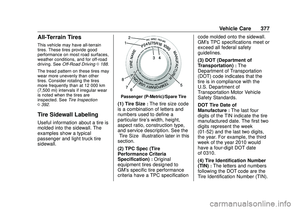
Tire Sidewall Labeling
Useful information about a tire is
molded into the sidewall. The
examples show a typical
passenger and light truck tire
sidewall.
Passenger (P-Metric)/Spare Tire
(1) Tire Size:The tire size code
is a combination of letters and
numbers used to define a
particular tire's width, height,
aspect ratio, construction type,
and service description. See the
“Tire Size” illustration later in this
section.
(2) TPC Spec (Tire
Performance Criteria
Specification)
:Original
equipment tires designed to
GM's specific tire performance
criteria have a TPC specification code molded onto the sidewall.
GM's TPC specifications meet or
exceed all federal safety
guidelines.
(3) DOT (Department of
Transportation)
:The
Department of Transportation
(DOT) code indicates that the
tire is in compliance with the
U.S. Department of
Transportation Motor Vehicle
Safety Standards.
DOT Tire Date of
Manufacture
:The last four
digits of the TIN indicate the tire
manufactured date. The first two
digits represent the week
(01-52) and the last two digits,
the year. For example, the third
week of the year 2010 would
have a four-digit DOT date
of 0310.
(4) Tire Identification Number
(TIN)
:The letters and numbers
following the DOT code are the
Tire Identification Number (TIN).
Page 379 of 495
Chevrolet Silverado Owner Manual (GMNA-Localizing-U.S./Canada/Mexico-
13337620) - 2020 - CTC - 1/27/20
378 Vehicle Care
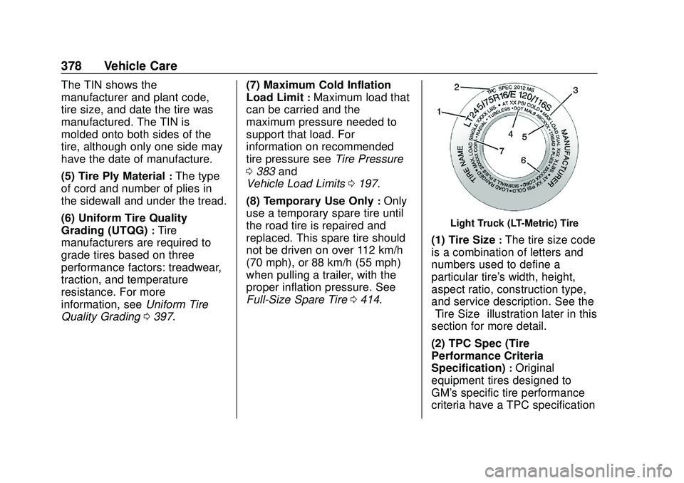
The TIN shows the
manufacturer and plant code,
tire size, and date the tire was
manufactured. The TIN is
molded onto both sides of the
tire, although only one side may
have the date of manufacture.
(5) Tire Ply Material
:The type
of cord and number of plies in
the sidewall and under the tread.
(6) Uniform Tire Quality
Grading (UTQG)
:Tire
manufacturers are required to
grade tires based on three
performance factors: treadwear,
traction, and temperature
resistance. For more
information, see Uniform Tire
Quality Grading 0397. (7) Maximum Cold Inflation
Load Limit
:Maximum load that
can be carried and the
maximum pressure needed to
support that load. For
information on recommended
tire pressure see Tire Pressure
0 383 and
Vehicle Load Limits 0197.
(8) Temporary Use Only
:Only
use a temporary spare tire until
the road tire is repaired and
replaced. This spare tire should
not be driven on over 112 km/h
(70 mph), or 88 km/h (55 mph)
when pulling a trailer, with the
proper inflation pressure. See
Full-Size Spare Tire 0414.
Light Truck (LT-Metric) Tire
(1) Tire Size:The tire size code
is a combination of letters and
numbers used to define a
particular tire's width, height,
aspect ratio, construction type,
and service description. See the
“Tire Size” illustration later in this
section for more detail.
(2) TPC Spec (Tire
Performance Criteria
Specification)
:Original
equipment tires designed to
GM's specific tire performance
criteria have a TPC specification