Page 9 of 316

4M1012721BA
Quick access
PESOGKED oe esciee vo acres vo asteame ww awe 81
— Vehicle key holder
Depending on equipment:
— Audi music interface .......... 213
—Audi phone box ............... 167
—SDicard readers. we.isi ccna eve 210
@ Electromechanical parking brake
BUEEGN segue ¢ s enme ¢ x ae © 2 eee e 104
@9 Automatic transmission selector
LEVEN scoop: « & eres ¢ o ane a 2 eee Fe 96
@ [START ENGINE STOP] button .... 94
@ Steering wheel adjustment ...... 64
@3) Lever for:
— Cruise control system ......... 130
— Adaptive cruise assist .......... 134
@4 Connection port for the On Board
Diagnostic System (OBD) ........ 288
@3) Buttons for:
Lights as 5 2 egies 5 ¢ ewe yo ees & 45
—All-weather lights ............ 45
— Rear fog lights ............... 45
@8 Hood release ..............00-% 234
@2 Button for:
— Luggage compartment lid ...... 36
Exterior mirror adjustment ...... SL.
@9) Buttons for:
— Power windows ...........00. 40
— Child safety lock .............. 40
@ Tips
Some the equipment listed here is only instal-
led in certain models or is available as an op-
tion.
Indicator lights overview
The indicator lights in the instrument cluster
blink or turn on. They indicate functions or mal-
functions. Some warning and indicator lights
turn on when you switch the ignition on and must
turn off when the drive system is switched on or
while driving.
With some indicator lights, messages may ap-
pear and warning signals may sound. The indica-
tor lights and messages may be covered by other
displays. To show them again, select the second
tab for messages with the multifunction steering
wheel & page 12.
Some indicator lights in the display can display in
several colors.
A\ Central indicator light
If the A or indicator light turns on, check
the message in the instrument cluster.
The following indicator lights may be available,
depending on the vehicle equipment:
Red indicator lights
Central indicator light
=> page 7,
Instrument cluster
=> page 11
Safety belt
=> page 69
Engine start system
=>page 95
Transmission
=> page 99
Drive system
=> page 101,
Electrical system
=> page 242
Electromechanical parking brake
=> page 104
Electromechanical parking brake
=>page 105
Brake system
=> page 103, > page 105,
=> page 241
Brake system
=> page 103, > page 105,
=> page 241
Steering
=>page 110
Steering lock
=>page 110
Page 10 of 316

Quick access
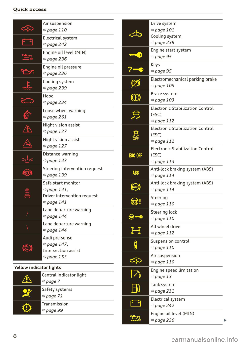
Air suspension
=> page 110
Electrical system
=> page 242
Engine oil level (MIN)
=> page 236
Engine oil pressure
=> page 236
Cooling system
=> page 239
Hood
=> page 234
Loose wheel warning
=> page 261
Night vision assist
=> page 127
Night vision assist
=> page 127
Distance warning
=> page 143
Steering intervention request
=> page 139
Safe start monitor
=> page 141,
Driver intervention request
=> page 141
Lane departure warning
=> page 144
Lane departure warning
=> page 144
Audi pre sense
=> page 147,
Intersection assist
= page 153
Yellow indicator lights
Central indicator light
>page 7
Safety systems
=> page 71
Transmission
=> page 99
Drive system
=> page 101
Cooling system
=> page 239
Engine start system
=>page 95
Keys
>page 95
Electromechanical parking brake
=>page 105
Brake system
=> page 103
Electronic Stabilization Control
(ESC)
=> page 112
Electronic Stabilization Control
(ESC)
=page 112
Electronic Stabilization Control
(ESC)
=> page 113
Anti-lock braking system (ABS)
>page 114
Anti-lock braking system (ABS)
=>page 114
Steering
=>page 110
Steering lock
=>page 110
All wheel drive
=> page 112
Suspension control
=>page 110
Air suspension
=>page 110
Engine speed limitation
=> page 13
Tank system
=> page 231
Electrical system
=> page 242
Engine oil level (MIN)
= page 236
Page 11 of 316

4M1012721BA
Quick access
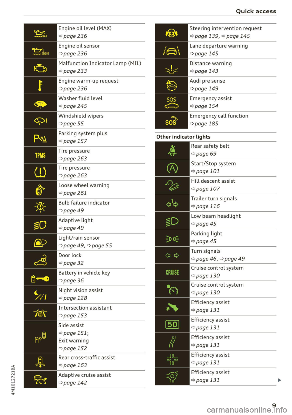
Engine oil level (MAX) Steering intervention request
=> page 236 => page 139, >page 145
Engine oil sensor
=> page 236
Malfunction Indicator Lamp (MIL)
Lane departure warning
=>page 145
Distance warning
=> page 233 => page 143
Engine warm-up request Audi pre sense
=> page 236 =>page 149
Washer fluid level Emergency assist
=>page 245 => page 154
Windshield wipers Emergency call function
=>page 55 =>page 185
Other
indicator lights
Rear safety belt
=> page 69
Parking system plus
=>page 157
Tire pressure
=> page 263
: Start/Stop system
Tire pressure > page 101
=> page 263
Hill descent assist
Loose wheel warning © page 107
=> page 261
5 An Trailer turn signals
Bulb failure indicator
= page 116
= page 49
—— Low beam headlight
Adaptive light >page 45
=> page 49 es : Parking light
Light/rain sensor page 45
= page 49, > page 55 ps Door lock Turn signals
oor loc| => page 46, > page 49
=> page 32
: : Cruise control system
Battery in vehicle key ange 130
=> page 36
Night vision
assist
=> page 128
Cruise control system
=> page 130
Efficiency assist
Intersection assistant => page 131
=> page 153
peg Efficiency assist
Side assist page 131
=> page 151;
P g . Efficiency assist
Exit warning > 131
> page 152 Page
Efficiency assist
> page 131
Rear cross-traffic assist
=> page 163
Adaptive cruise assist | | Efficiency assist
page 142 => page 131 >
Page 12 of 316

Quick access
Adaptive cruise assist
=> page 136
Adaptive cruise assist
=> page 136
Adaptive cruise assist
=> page 136
Adaptive cruise assist
=> page 136
Lane guidance for adaptive cruise
assist
=> page 136
Lane departure warning
=> page 144
High beams
=> page 46
High beam assistant
=> page 46
Laser lights
=> page 47
Rear safety belt
=> page 69
Rear safety belt
=> page 69
Transmission
=> page 99
Convenience key
=>page 95
Electromechanical parking brake
=>page 105
Electromechanical parking brake
=>page 105
Hill descent assist
=> page 107
Air suspension
=>page 110
High beam assistant
=> page 46
Door lock
> page 32
10
Child safety lock
=> page 40
Speed warning system
= page 123
Speed warning system
> page 123
Camera-based traffic sign recog-
nition
=> page 124
Night vision assist
=> page 128
Cruise control system
CS
page 130
Cruise control system
=> page 130
Intersection assistant
=> page 153
Side assist
=>page 151
Distance warning
=> page 143
Rear cross-traffic assist
=> page 163
Adaptive cruise assist
=> page 142,
Efficiency assist
=> page 133
Adaptive cruise assist
=> page 139
Lane guidance for adaptive cruise
assist
=> page 136
Lane departure warning
=> page 144
Lane departure warning
=>page 145
Audi pre sense
=> page 149
Emergency assist
=>page 154
Page 13 of 316

4M1012721BA
Instrument cluster
Instrument cluster
Instrument cluster overview
3:50™
12/5/2019
2800 mi
CHL Oe
Fig. 2 Instrument cluster overview (Audi virtual cockpit)
Depending on the vehicle equipment, the follow-
ing items may appear in the instrument cluster:
@) Display
— Engine coolant temperature =E . . 13
(2) Left dial
13 12 12
(S) Status line (one or two lines)
) Right dial
— Convenience display
— Speedometer
Fuellevel VY ......... 0... e ee eee 231
Right additional display with speed-
ometer
(9) Left additional display with:
— Gear... eee eee ee eee eee 96
— Audi drive select mode ......... 108
Z\ WARNING
If there is a severe malfunction in the instru-
ment cluster, the display may turn off. The
indicator light may also turn on. Stop the ve-
hicle safely. See an authorized Audi dealer or
authorized Audi Service Facility for assistance.
Par
Pa
@) Tips
— You can select the units used for tempera-
ture, speed, and other measurements in the
Infotainment system > page 225.
— Speeds are displayed in mph (miles per
hour) or km/h (kilometers per hour).
— If there is a malfunction in the instrument
cluster, DEF will appear in the trip odometer
display. Have the malfunction corrected as
soon as possible.
— Certain instrument cluster content can also
be displayed in the head-up display*
=> page 24.
— Certain settings are stored automatically in
the active personal profile.
Loading a personal
profile
Coton}
Stare ce re RC
Eater)
lol 4
Switch profile Ps
Fig. 3 Instrument cluster: loading a personal profile >
11
Page 14 of 316

Instrument cluster
You can manage personal profiles in the MMI
=> page 28. Before driving, you can select your
personal profile in the instrument cluster and ap-
ply customized vehicle settings, such as the seat
position.
Requirement: the driver's door must have been
opened and the ignition must not be switched
on.
> Confirm the displayed profile @, or
> To load another profile, select and confirm
Switch profile @).
> Select and confirm the desired profile. The
user-specific settings will load.
> To cancel the seat, mirror, and steering column
adjustment, select Cancel.
G) Tips
For more information and usage options for
personal profiles, see > page 28.
Operating
HAY ele
12/05/2017
Fig. 4 Instrument cluster: driver information system
Selecting a tab
> Press the button @) repeatedly until the
desired tab is selected.
Returning to functions at higher levels
> Press the D button ©).
Opening and closing the menu
> Press the [=] button ©.
Selecting
and confirming a function
Requirement: a menu or list must be displayed.
> To select a function, turn the left thumbwheel
@ to the desired function.
> To confirm a selection, press the left thumb-
wheel (7).
Switching the view
> Press the VIEW button @).
The following tabs may be available, depending
on vehicle equipment:
Fig. 5 Left side of multifunction steering wheel
Information is organized within various tabs (@)
in the instrument cluster. The tab contents are
displayed in the central area (2).
Requirement: the ignition must be switched on.
12
First tab Vehicle functions > page 14
Second tab | Driver messages (this is only dis-
played if at least one indicator
light/message is being displayed)
Third tab Night vision assist (this is only dis-
played if the night vision assist
has been activated) > page 126
Fourth tab | Radio > page 202
Media > page 215
Fifth tab Telephone > page 176
Sixth tab Navigation > page 186
Adjusting the display
RAZ-0673
Fig. 6 Upper display: adjusting the display
Page 15 of 316

4M1012721BA
Instrument cluster
Switching the view
> Press the VIEW button to switch between the
default view @ and the enhanced view (2).
Adjusting the layout
Depending on the vehicle equipment, various lay-
outs may be available.
> Applies to: MMI: Select on the home screen:
SETTINGS > Display & brightness > Virtual
cockpit.
> To adjust the desired layout, press @).
Adjusting the additional display
Depending on the vehicle equipment, the addi-
tional displays that can be selected may vary.
> Applies to: MMI: Select on the home screen:
SETTINGS > Display & brightness > Virtual
cockpit > (Configure).
> Select the desired additional display.
Reducing the display
Depending on the vehicle equipment, you can
hide the central area in the instrument cluster.
> Select on the instrument cluster: vehicle func-
tions tab > EE] button > Reduced display.
Coolant temperature
display
The coolant temperature display @) > page 11
only functions when the ignition is switched on.
To reduce the risk of engine damage, please ob-
serve the following notes about the temperature
ranges.
Cold range
If only the LEDs at the bottom of the gauge turn
on, the engine has not reached operating tem-
perature yet. Avoid high engine speeds, full accel-
eration, and heavy engine loads.
Normal range
The engine has reached its operating tempera-
ture once the LEDs up to the center of the gauge
turn on. If the || indicator light in the instru-
ment cluster display turns on, the coolant tem-
perature is too high > page 239.
CG) Note
— Auxiliary headlights and other accessories in
front of the air intake impair the cooling ef-
fect of the coolant. This increases the risk of
the engine overheating during high outside
temperatures and heavy engine load.
—The front spoiler also helps to distribute
cooling air correctly while driving. If the
spoiler is damaged, the cooling effect will
be impaired and the risk of the engine over-
heating will increase. See an authorized
Audi dealer or authorized Audi Service Fa-
cility for assistance.
Tachometer
The tachometer 2) > page 11 displays the engine
speed in revolutions per minute (RPM). The be-
ginning of the red zone in the tachometer indi-
cates the maximum permissible engine speed for
all gears once the engine has been broken in. Be-
fore reaching the red zone, you should shift into
the next higher gear, select the "D" or "S" selec-
tor lever position, or remove your foot from the
accelerator pedal.
Engine speed limitation
If the Ay indicator light turns on, the engine will
be automatically limited to the RPM displayed in
the instrument cluster. This will protect the en-
gine components, for example during a cold start
or from overheating.
The engine speed limitation will be deactivated
once the engine has reached its normal operating
temperature and you have released the accelera-
tor pedal.
If the engine speed limitation was activated by
an engine control malfunction, the By indicator
light also turns on. Make sure the engine speed
does not go above the speed displayed, for exam-
ple when downshifting. Drive to an authorized
Audi dealer or authorized Audi Service Facility im-
mediately to have the malfunction corrected.
() Note
The needle in the tachometer may only be in
the red area of the gauge for a short period of >
13
Page 16 of 316

Instrument cluster
time before there is a risk of damaging the
engine. The location where the red zone be-
gins varies depending on the engine.
Odometer
The trip odometer and odometer are displayed in
the status line ©) > page 11.
The trip odometer shows the distance driven
since it was last reset. It can be used to measure
short distances. The odometer shows the total
distance that the vehicle has been driven.
Resetting the trip odometer
> Select on the instrument cluster: vehicle func-
tions tab > [| button > Reset mi.
@ Tips
Distances are displayed in mi (miles) or km
(kilometers).
Outside temperature
display
The outside temperature is displayed in the sta-
tus line @) > page 11.
If your vehicle is stationary or if you are driving at
very low speeds, the temperature displayed in
the instrument cluster may be slightly higher
than the actual temperature outside due to heat
radiating from the engine.
At temperatures below 41 °F (+5 °C), a snowflake
symbol appears in front of the temperature dis-
play > A.
ZX WARNING
Do not assume the roads are free of ice based
on the outside temperature display. Be aware
that there may be ice on roads even when the
outside temperature is around 41 °F (+5 °C)
and that ice can increase the risk of accidents.
14
Engine oil temperature
indicator
Depending on the vehicle equipment, the engine
oil temperature %7 may be indicated by a bar in
the instrument cluster.
Requirement: the vehicle functions tab must be
selected.
> Switch to the enhanced view > page 12.
When engine oil temperatures are low, the dis-
play --- °F (--- °C) appears in the instrument clus-
ter. The engine has reached its operating temper-
ature when the engine oil temperature is be-
tween 176 °F (80 °C) and 248 °F (120 °C) under
normal driving conditions. The engine oil temper-
ature may be higher if there is heavy engine load
and high temperatures outside. This is not a
cause for concern as long as the ee} => page 236
or 3 => page 236 indicator lights do not turn on.
Vehicle functions
LO Ta TN]
The trip computer is displayed in the first tab of
the driver information system. Additional vehicle
functions can be accessed depending on the vehi-
cle equipment.
> Press the £] button on the multifunction steer-
ing wheel.
— On-board computer > page 14
— Reduced display > page 13
— Reset trip odometer > page 14
On-board computer
Resetting values to zero
Requirement: the Consumption, Short-term
memory, or Long-term memory display must be
selected.
> To reset the values in one of the memories to
zero, press and hold the left thumbwheel on
the multifunction steering wheel for one sec-
ond, or
>» Select on the instrument cluster: vehicle func-
tions tab > EI button > Reset mi.