2020 AUDI A3 sensor
[x] Cancel search: sensorPage 139 of 400
8V2012721BK
Parking aid
Parking system plus
Description
Applies to: vehicles with parking system plus/park assist
B8V-0686
RAH-8914
Fig. 131 Infotainment system: visual distance display
The parking system plus uses audio and visual
warnings to help you avoid obstacles when park-
ing.
Sensors are located in the front and rear bump-
ers. If these detect an obstacle, audible and visu-
al signals warn you.
Make sure the sensors are not covered by stick-
ers, deposits or any other obstructions as it may
impair the function of the system. For informa-
tion on cleaning, see > page 342.
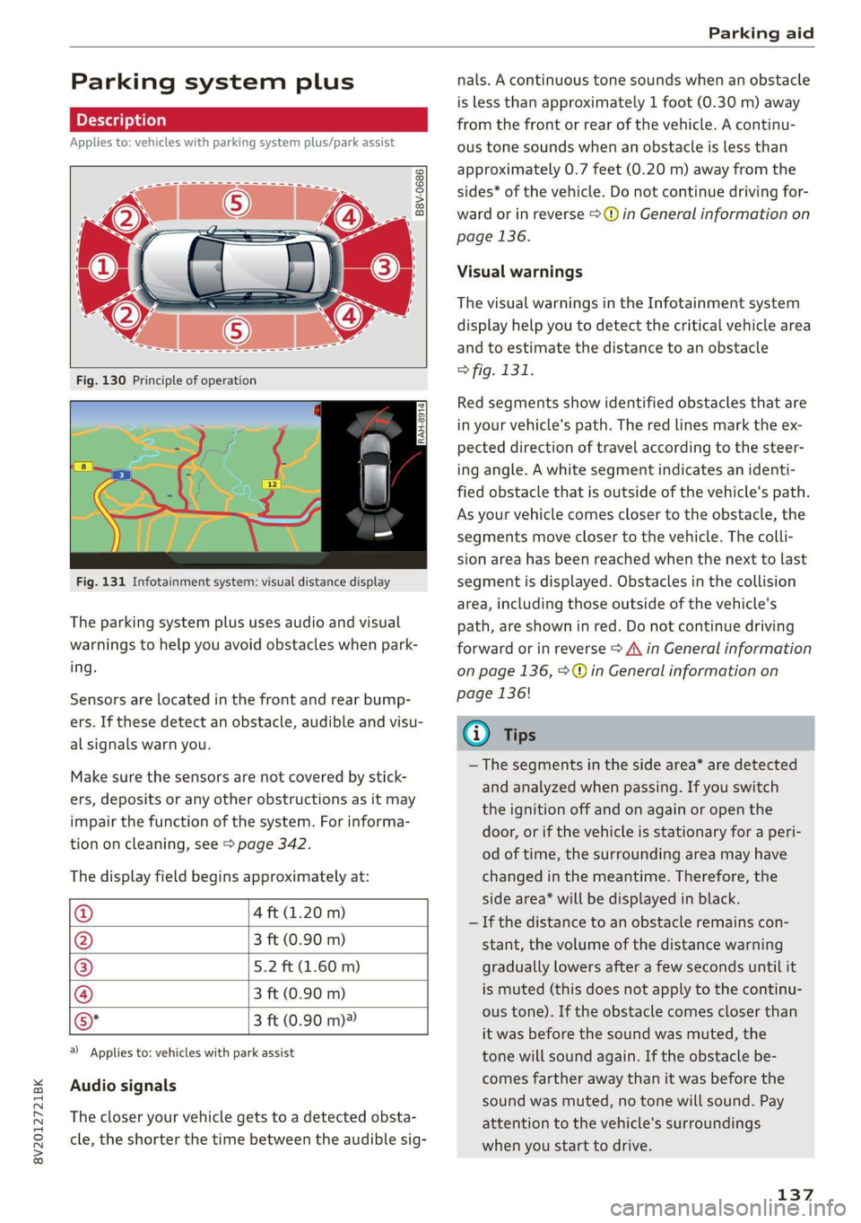
The display field begins approximately at:
@ 4 ft (1.20 m)
@ 3 ft (0.90 m)
® 5.2 ft (1.60 m)
@ 3 ft (0.90 m)
©* 3 ft (0.90 m)®
@) Applies to: vehicles with park assist
Audio signals
The closer your vehicle gets to a detected obsta-
cle, the shorter the time between the audible sig-
nals. A continuous tone sounds when an obstacle
is less than approximately 1 foot (0.30 m) away
from the front or rear of the vehicle. A continu-
ous tone sounds when an obstacle is less than
approximately 0.7 feet (0.20 m) away from the
sides* of the vehicle. Do not continue driving for-
ward or in reverse >@ in General information on
page 136.
Visual warnings
The visual warnings in the Infotainment system
display help you to detect the critical vehicle area
and to estimate the distance to an obstacle
> fig. 131.
Red segments show identified obstacles that are
in your vehicle's path. The red lines mark the ex-
pected direction of travel according to the steer-
ing angle. A white segment indicates an identi-
fied obstacle that is outside of the vehicle's path.
As your vehicle comes closer to the obstacle, the
segments move closer to the vehicle. The colli-
sion area has been reached when the next to last
segment is displayed. Obstacles in the collision
area, including those outside of the vehicle's
path, are shown in red. Do not continue driving
forward or in reverse > A\ in General information
on page 136, >@ in General information on
page 136!
G) Tips
— The segments in the side area* are detected
and analyzed when passing. If you switch
the ignition off and on again or open the
door, or if the vehicle is stationary for a peri-
od of time, the surrounding area may have
changed in the meantime. Therefore, the
side area* will be displayed in black.
— If the distance to an obstacle remains con-
stant, the volume of the distance warning
gradually lowers after a few seconds until it
is muted (this does not apply to the continu-
ous tone). If the obstacle comes closer than
it was before the sound was muted, the
tone will sound again. If the obstacle be-
comes farther away than it was before the
sound was muted, no tone will sound. Pay
attention to the vehicle's surroundings
when you start to drive.
137
Page 140 of 400
Parking aid
Switching on and off
Applies to: vehicles with parking system plus/park assist
2 + 3
S| 2 ©
a.
Fig. 132 Center console: parking aid button
Switching on and off
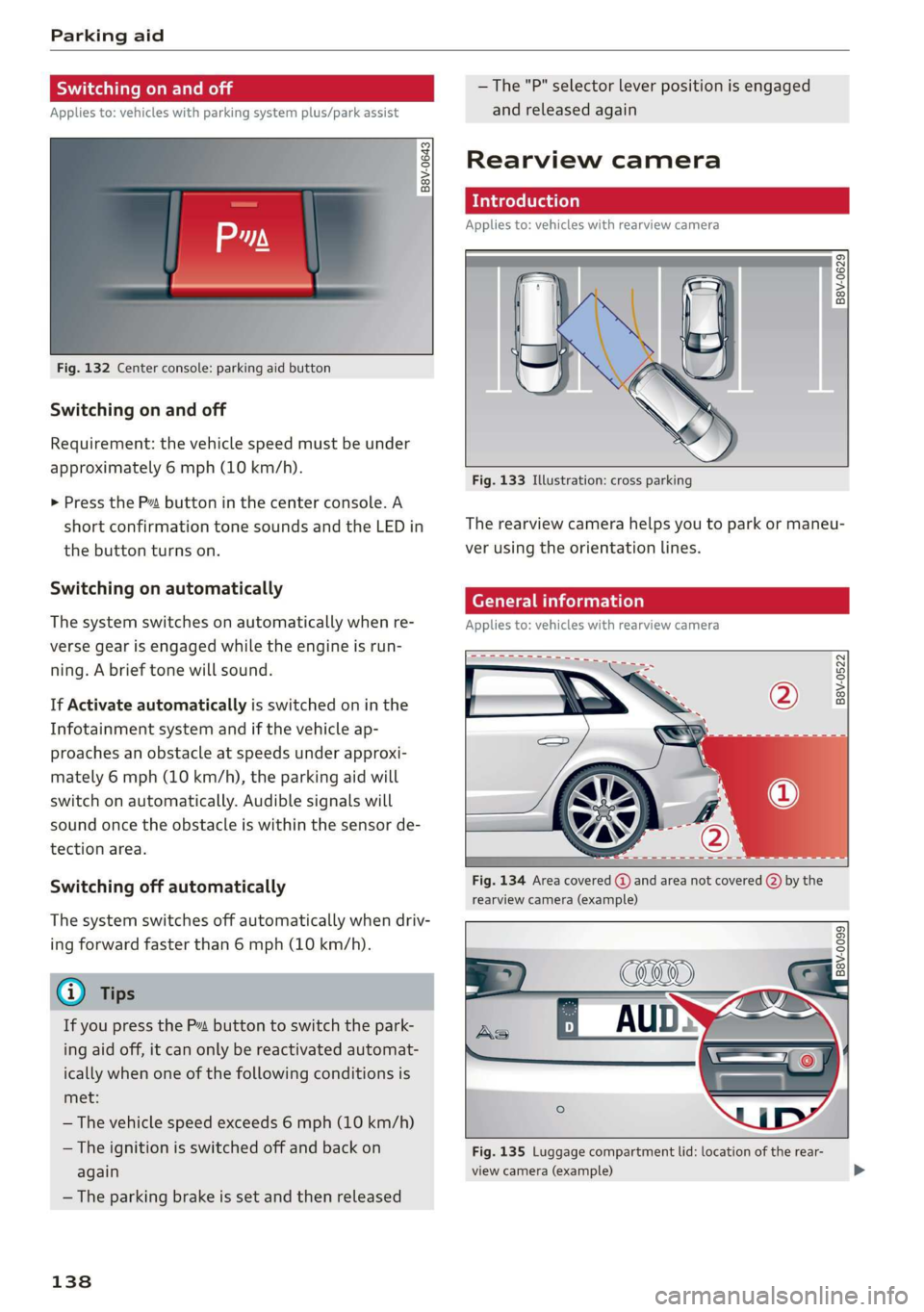
Requirement: the vehicle speed must be under
approximately 6 mph (10 km/h).
> Press the Pvt button in the center console. A
short confirmation tone sounds and the LED in
the button turns on.
Switching on automatically
The system switches on automatically when re-
verse gear is engaged while the engine is run-
ning. A brief tone will sound.
If Activate automatically is switched on in the
Infotainment system and if the vehicle ap-
proaches an obstacle at speeds under approxi-
mately 6 mph (10 km/h), the parking aid will
switch on automatically. Audible signals will
sound once the obstacle is within the sensor de-
tection area.
Switching off automatically
The system switches off automatically when driv-
ing forward faster than 6 mph (10 km/h).
@ Tips
If you press the Ps button to switch the park-
ing aid off, it can only be reactivated automat-
ically when one of the following conditions is
met:
— The vehicle speed exceeds 6 mph (10 km/h)
— The ignition is switched off and back on
again
— The parking brake is set and then released
138
—The "P" selector lever position is engaged
and released again
Rearview camera
Introduction
Applies to: vehicles with rearview camera
B8V-0629
Fig. 133 Illustration: cross parking
The rearview camera helps you to park or maneu-
ver using the orientation lines.
Cee Mc Lo)
Applies to: vehicles with rearview camera
B8V-0522
Fig. 134 Area covered @ and area not covered (2) by the
rearview camera (example)
'8V-0099 Bi
Fig. 135 Luggage compartment lid: location of the rear-
view camera (example)
Page 142 of 400
Parking aid
Applies to: vehicles with rearview camera
This view may be used when parking in a garage
or ina parking space.
Fig. 137 Infotainment system: aligning the vehicle
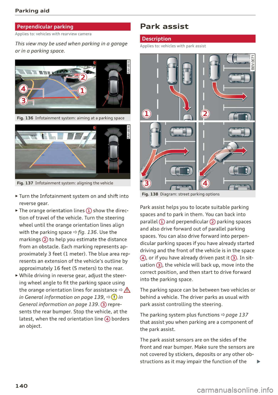
> Turn the Infotainment system on and shift into
reverse gear.
> The orange orientation lines @ show the direc-
tion of travel of the vehicle. Turn the steering
wheel until the orange orientation lines align
with the parking space > fig. 136. Use the
markings (2) to help you estimate the distance
from an obstacle. Each marking represents ap-
proximately 3 feet (1 meter). The blue area rep-
resents an extension of the vehicle's outline by
approximately 16 feet (5 meters) to the rear.
> While driving in reverse gear, adjust the steer-
ing wheel angle to fit the parking space using
the orange orientation lines for assistance > A\
in General information on page 139, >@) in
General information on page 139
sents the rear bumper. Stop the vehicle, at the
latest, when the red orientation line @) borders
an object.
repre-
140
Park assist
Applies to: vehicles with park assist
Fig. 138 Diagram: street parking options
Park assist helps you to locate suitable parking
spaces and to park in them. You can back into
parallel @) and perpendicular (2) parking spaces
and also drive forward out of parallel parking
spaces. You can also drive forward into perpen-
dicular parking spaces if you have already started
driving and the front of the vehicle is in the space
(4), or if you have already driven past it @). In sit-
uation @), the vehicle will back up, move into the
correct position, and then start to drive forward
into the parking space.
The parking space can be between two vehicles or
behind a vehicle. The driver parks as usual with
park assist controlling the steering.
The parking system plus functions > page 137
that assist you when parking are a component of
the park assist.
The park assist sensors are on the sides of the
front and rear bumper. Make sure the sensors are
not covered by stickers, deposits or any other ob-
structions as it may impair the function of the >
Page 147 of 400
8V2012721BK
Parking aid
Entertainment fader - The volume of the audio/
video source is Lowered when the parking system
is turned on.
G) Tips
— Several menus can be accessed with the
right control button only when the parking
aid is active.
— The new level is demonstrated briefly* when
the volume is adjusted.
— Certain settings are automatically stored
and assigned to the remote control key be-
ing used.
Error messages
Applies to: vehicles with parking system plus/rearview cam-
era/park assist
wm Rear parking aid: malfunction! Obstacles
cannot be detected
w Front parking aid: malfunction! Obstacles
cannot be detected
ww Parking aid: malfunction! Obstacles cannot
be detected
When one of these messages appears, there is a
system malfunction. The LED in the Pa button al-
so blinks when switching it on. The relevant mes-
sage only appears again when you manually acti-
vate the parking aid with the button.
Rear parking aid: obstacle detection restrict-
ed
The rear cross-traffic assist* > page 134, Rear
cross-traffic assist is not available. Either the ESC
is switched off, or the radar sensors may be cov-
ered by a bike rack, stickers, leaves, snow or other
objects. Switch the ESC on, or clean the area in
front of the sensors if necessary > page 132,
fig. 127. If this message continues to be dis-
played, drive immediately to an authorized Audi
dealer or authorized Audi Service Facility to have
the malfunction repaired.
Parking system plus*/Park assist*
If a sensor or speaker is faulty, the P4 symbol
will appear in front of/behind the vehicle in the
Infotainment system display. If a rear sensor is
faulty, only obstacles that are in areas @ and (2)
are shown > page 137, fig. 130. If a front sensor
is faulty, only obstacles that are in areas (3) and
@ are shown.
145
Page 174 of 400
Telephone
— The mobile device may become hot during
wireless charging. Pay attention to the tem-
perature of your mobile device and be care-
ful when removing it from the Audi phone
box.
—An alternating magnetic field is used for
wireless charging. Maintain a minimum dis-
tance of approximately 2.4 in (6 cm) to the
Audi phone box charging plate. The thresh-
olds for prolonged exposure at this distance
comply with ICNIRP1998. Therefore, inter-
actions such as irritation of sensory organs,
malfunctions of active implants (such as
pacemakers, infusion pumps, or neurosti-
mulators) or effects on passive implants
(such as prosthetic limbs) is highly unlikely.
If you have an implant, consult a medical
specialist if you have any questions.
@) Note
Applicable to U.S.A.
Operation of the Audi phone box is subject to
the following requirements of the Federal
Communications Commission:
— This is a CONSUMER device.
— BEFORE USE, you MUST REGISTER THIS DE-
VICE with your wireless provider and have
your provider’s consent. Most wireless pro-
viders consent to the use of signal boosters.
Some providers may not consent to the use
of this device on their network. If you are
unsure, contact your service provider.
— You MUST operate this device with approved
antennas and cables as specified by the
manufacturer. Antennas MUST be installed
at least 20 cm (8 inches) from any person.
— You MUST cease operating this device im-
mediately if requested by the FCC or a li-
censed wireless service provider.
— WARNING: E911 location information may
not be provided or may be inaccurate for
calls served by using this device.
@) Note
Applicable to Canada
In Canada, operation of a Zone Enhancer,
such as an Audi Phone Box, is subject to the
following requirements of the Innovation,
172
Science and Economic Development Canada
(ISED):
—This is a CONSUMER device.
— BEFORE USE, you MUST meet all require-
ments set out in CPC-2-1-05.
— You MUST operate this device with approved
antennas and cables as specified by the
manufacturer. Antennas MUST NOT be in-
stalled within 20 cm of any person.
— You MUST cease operating this device im-
mediately if requested by ISED or a licensed
wireless service provider.
— WARNING: £911 location information may
not be provided or may be inaccurate for
calls served by using this device.
G) Tips
— Placing the mobile device in a bag or protec-
tive sleeve inside the Audi phone box can in-
terfere with the connection to the external
antenna”.
— Metallic objects in the Audi phone box block
the wireless charging of your mobile device
and calls made using the exterior antenna”*.
—The charging time and temperature will vary
depending on the mobile device being used.
— Your mobile device can only be charged in
the Audi phone box when the ignition is
switched on.
— To reduce the risk of malfunctions, make
sure the mobile device is positioned correct-
ly in the Audi phone box.
—The maximum charging output is 5 W.
— Strong transmission quality* cannot be
guaranteed if more than one mobile device
is in the box.
— Only one mobile device at a time can be
charged wirelessly in the Audi phone box.
— Audi recommends using Audi Genuine Ac-
cessories. Audi has verified their reliability,
safety, and suitability.
— You can purchase a USB adapter from an au-
thorized Audi dealer or authorized Audi
Service Facility, or at specialty stores.
— If you place your remote control key togeth-
er with your mobile device in the Audi phone
box, it may cause your mobile device to stop
charging if wireless charging is active.
Page 240 of 400
Driving safety
> ALWAYS adjust your speed to road, traffic and
weather conditions.
> Take frequent breaks on long trips. Do not drive
for more than two hours at a stretch.
> Do NOT drive when you are tired, under pres-
sure or when you are stressed.
ZX WARNING
Impaired driving safety increases the risk of
serious personal injury and death whenever a
vehicle is being used.
Safety systems monitoring
The Ba indicator light in the instrument cluster
monitors the safety systems such as the airbags
(including the control modules, sensors, and wir-
ing) and the belt tensioners. It turns on when you
switch the ignition on and turns off after several
seconds.
If the Ea indicator light does not turn on when
the ignition is switched on, does not turn off af-
ter several seconds, or turns on or flashes while
driving, there may be a malfunction in one of the
safety systems. Drive to an authorized Audi deal-
er or authorized Audi Service Facility immediately
to have the malfunction corrected.
Z\ WARNING
Have the malfunction in the safety systems in-
spected immediately. Otherwise, there is a
risk that the systems may not activate during
an accident, which increases the risk of seri-
ous or fatal injury.
238
Correct passenger
seating positions
Proper seating position for the driver
The proper driver seating position is important
for safe, relaxed driving.
B4G-0375
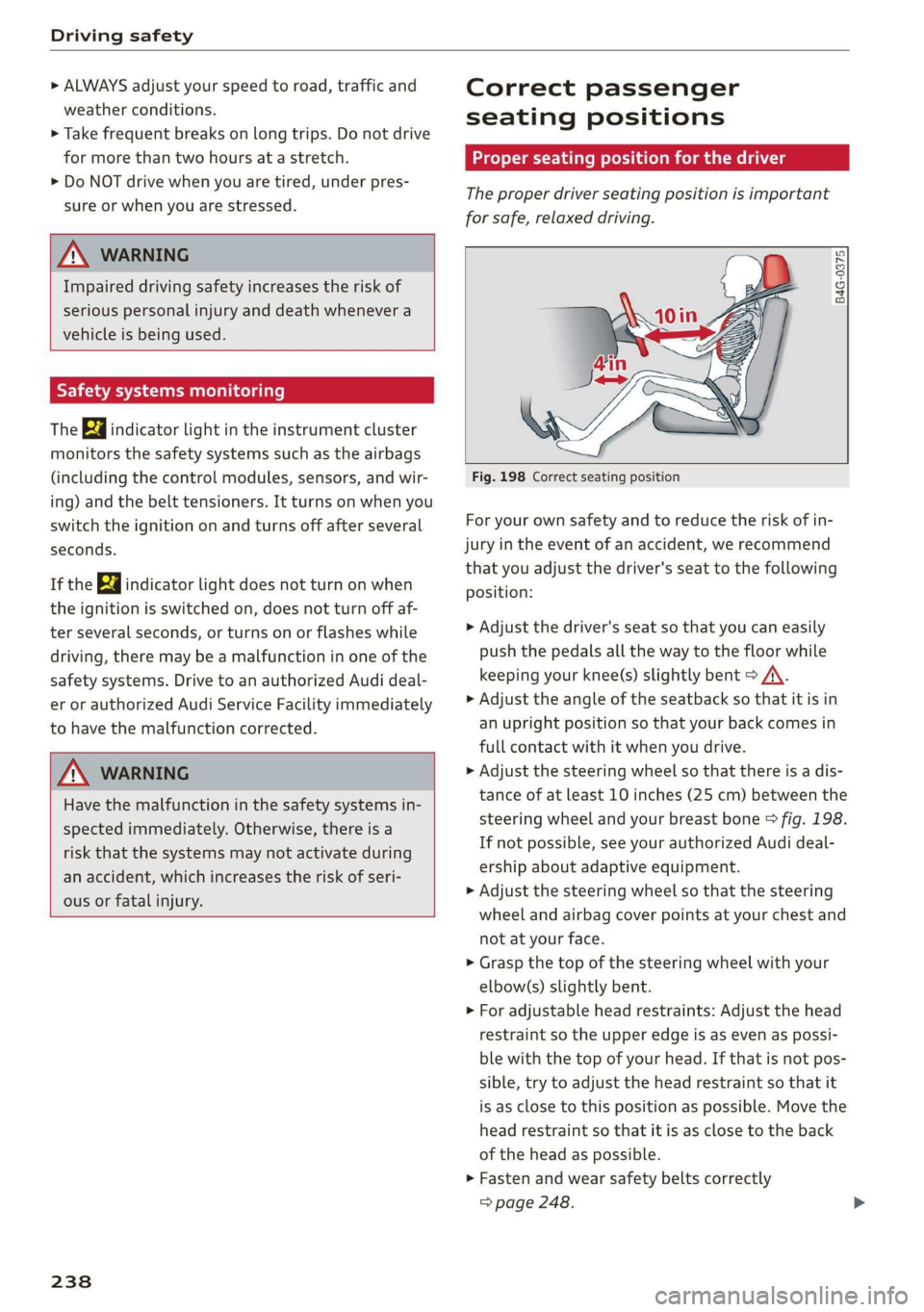
Fig. 198 Correct seating position
For your own safety and to reduce the risk of in-
jury in the event of an accident, we recommend
that you adjust the driver's seat to the following
position:
> Adjust the driver's seat so that you can easily
push the pedals all the way to the floor while
keeping your knee(s) slightly bent > A\.
> Adjust the angle of the seatback so that it is in
an upright position so that your back comes in
full contact with it when you drive.
> Adjust the steering wheel so that there is a dis-
tance of at least 10 inches (25 cm) between the
steering wheel and your breast bone © fig. 198.
If not possible, see your authorized Audi deal-
ership about adaptive equipment.
> Adjust the steering wheel so that the steering
wheel and airbag cover points at your chest and
not at your face.
> Grasp the top of the steering wheel with your
elbow(s) slightly bent.
> For adjustable head restraints: Adjust the head
restraint so the upper edge is as even as possi-
ble with the top of your head. If that is not pos-
sible, try to adjust the head restraint so that it
is as close to this position as possible. Move the
head restraint so that it is as close to the back
of the head as possible.
> Fasten and wear safety belts correctly
=> page 248.
Page 244 of 400

Driving safety
1 Coley maar Mela Mealy -aed (el)
Always use floor mats that can be securely at-
tached to the floor mat fasteners and do not in-
terfere with the free movement of the pedals.
> Make sure that the floor mats are properly se-
cured and cannot move and interfere with the
pedals > A\.
Use only floor mats that leave the pedal area un-
obstructed and that are firmly secured so that
they cannot slip out of position. You can obtain
suitable floor mats from your authorized Audi
Dealer.
Floor mat fasteners are installed in your Audi.
Floor mats used in your vehicle must be attached
to these fasteners. Properly securing the floor
mats will prevent them from sliding into posi-
tions that could interfere with the pedals or im-
pair safe operation of your vehicle in other ways.
ZA\ WARNING
Pedals that cannot move freely can result ina
loss of vehicle control and increase the risk of
serious personal injury.
— Always make sure that floor mats are prop-
erly secured.
— Never place or install floor mats or other
floor coverings in the vehicle that cannot be
properly secured in place to prevent them
from slipping and interfering with the ped-
als or the ability to control the vehicle.
— Never place or install floor mats or other
floor coverings on top of already installed
floor mats. Additional floor mats and other
coverings will reduce the size of the pedal
area and interfere with the pedals.
— Always properly reinstall and secure floor
mats that have been taken out for cleaning.
— Always make sure that objects cannot fall in-
to the driver footwell while the vehicle is
moving. Objects can become trapped under
the brake pedal and accelerator pedal caus-
ing a loss of vehicle control.
242
Active rollover
protection system
Applies to: vehicles with power top
The rollover protection system protects vehicle
occupants in the event of a rollover.
B8V-0333
Fig. 199 Rear seats: rollbar deployment range
B8V-0334
Fig. 200 Rear seats: deployed rollbar
The active rollover protection system consists of:
— two rollbars
— the safety belts with belt tensioners
— the windshield frame
—the rollover sensors
The active rollover protection system provides
additional safety in the event of a rollover. Within
milliseconds, sensors deploy two rollbars located
behind the head restraints in the rear seats
© fig. 200.
The rollbars, reinforced windshield frame and
belt tensioners help protect front and rear pas-
sengers in the event of a rollover.
The rollover protection system functions when
the power top is both open and closed.
Page 245 of 400

8V2012721BK
Driving safety
AN WARNING
Do not use the area behind the rear seat head
restraints > fig. 199 as a seat or storage area.
This is the area where the rollbars deploy. If
the rollover protection system is triggered,
objects placed there can be propelled through
the vehicle and make it more difficult for the
rollbars to deploy. This increases the risk for
serious or life-threatening injuries.
When is rollover protection deployed?
Applies to: vehicles with power top
Rollover protection deploys in a collision or roll-
over.
Depending on the collision, sensors throughout
the vehicle and the control module trigger the
rollover system to deploy.
For safety reasons, rollover protection also de-
ploys during front, side and rear collisions above
a certain level of severity.
Retracting rollover protection
Applies to: vehicles with power top
B8V-0335
B8V-0336
Fig. 202 Deployed rollbar with power top frame facing up-
ward.
If the rollover protection has triggered but the
vehicle was not involved in an accident, you can
retract the rollover protection yourself in an
emergency. Drive to an authorized Audi dealer or
authorized Audi Service Facility immediately to
have the malfunction corrected.
With the power top open
> Pull the loop upward in the direction of the ar-
row and hold it in place > fig. 201.
> Slide the rollbar down.
> Release the loop just before the rollbar reaches
its end position (1-2 in. / 3-5 cm).
> Press the rollbar down until it stops.
> Make sure the rollbar is secure before releasing
its
> Close the cover (@) > fig. 202.
> Repeat the procedure on the other rollbar.
With the power top closed
> Switch the ignition on.
> Press the power top switch to adjust the power
top frame until it is vertical > fig. 202.
> Pull the loop upward in the direction of the ar-
row and hold it in place > fig. 201.
> Slide the rollbar down.
> Release the loop just before the rollbar reaches
its end position (1-2 in. / 3-5 cm).
> Press the rollbar down until it stops.
> Make sure the rollbar is secure before releasing
it.
> Close the cover (@) > fig. 202.
> Repeat the procedure on the other rollbar.
> You can now close the power top again.
Z\ WARNING
— Make sure your head or other parts of your
body are not located in the area above the
rollbar
when pressing the rollbar down. If
the rollbar is not secured correctly, it could
deploy again as soon as you release it and
cause injuries.
— Have the rollover protection system checked
by and authorized Audi dealer or authorized
Audi Service Facility if it malfunctions. Oth-
erwise the system may not deploy correctly
in a collision.
243