2019 YAMAHA YZF-R6 panel
[x] Cancel search: panelPage 6 of 112
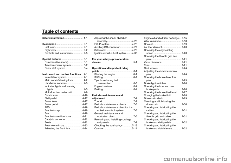
Table of contentsSafety information ............................ 1-1
Description ....................................... 2-1
Left view ......................................... 2-1
Right view ....................................... 2-2
Controls and instruments ............... 2-3
Special features ............................... 3-1
D-mode (drive mode)...................... 3-1
Traction control system .................. 3-2
Quick shift system .......................... 3-4
Instrument an d control functions ... 4-1
Immobilizer system......................... 4-1
Main switch/steering lock............... 4-2
Handlebar switches ........................ 4-3
Indicator lights and warning
lights............................................ 4-5
Multi-function meter unit ................ 4-8
Clutch lever .................................. 4-16
Shift pedal .................................... 4-17
Brake lever.................................... 4-17
Brake pedal .................................. 4-17
ABS .............................................. 4-18
Fuel tank cap ................................ 4-19
Fuel ............................................... 4-19
Fuel tank overflow hose ............... 4-21
Catalytic converter ....................... 4-22
Seats ............................................ 4-22
Rear view mirrors.......................... 4-23
Adjusting the front fork ................. 4-24 Adjusting the shock absorber
assembly.................................... 4-26
EXUP system ................................ 4-28
Auxiliary DC connector ................. 4-29
Sidestand ...................................... 4-29
Ignition circuit cut-off system ....... 4-30
For your safety – pre-operation
checks ............................................... 5-1
Operation an d important ri din g
points ................................................. 6-1
Starting the engine .......................... 6-1
Shifting ............................................ 6-2
Tips for reducing fuel consumption ................................ 6-3
Engine break-in ............................... 6-4
Parking ............................................ 6-4
Perio dic maintenance an d
a d justment ........................................ 7-1
Tool kit ............................................ 7-2
Periodic maintenance charts .......... 7-3
Periodic maintenance chart for the emission control system .............. 7-3
General maintenance and
lubrication chart ........................... 7-5
Removing and installing cowlings and panels ................................... 7-9
Checking the spark plugs ............. 7-13
Canister ......................................... 7-14 Engine oil and oil filter cartridge ... 7-15
Why Yamalube.............................. 7-18
Coolant ......................................... 7-19
Air filter element ............................ 7-20
Checking the engine idling
speed ........................................ 7-20
Checking the throttle grip free play ............................................ 7-21
Valve clearance............................. 7-21
Tires .............................................. 7-21
Cast wheels .................................. 7-24
Adjusting the clutch lever free play ............................................ 7-24
Checking the brake lever free
play ............................................ 7-25
Brake light switches ..................... 7-26
Checking the front and rear brake pads ................................ 7-26
Checking the brake fluid level ...... 7-27
Changing the brake fluid .............. 7-28
Drive chain slack........................... 7-29
Cleaning and lubricating the drive chain ................................. 7-30
Checking and lubricating the cables ........................................ 7-31
Checking and lubricating the
throttle grip and cable ............... 7-31
Checking and lubricating the brake and shift pedals............... 7-32
Checking and lubricating the brake and clutch levers ............. 7-32UBN6E2E0.book Page 1 Friday, December 7, 2018 2:56 PM
Page 66 of 112

Periodic maintenance an d a djustment
7-9
7
EAU18713
Removin g an d installin g cowl-
in gs an d panelsThe cowlings and panels shown need
to be removed to perform some of the
maintenance jobs described in this
chapter. Refer to this section each time
a cowling or panel needs to be re-
moved and installed.
EAU79983
Cowlin g A
To remove the cowling1. Remove panel A. (See page 7-13.)
2. Remove the bolts, quick fasten- ers, and quick fastener screw.
1. Cowling A
2. Cowling B
1
2
1. Cowling C
2. Cowling D
1. Panel A
2. Panel B
1
2
1
2
1. Cowling A
2. Bolt
3. Quick fastener screw
1
3
2
2
UBN6E2E0.book Page 9 Friday, December 7, 2018 2:56 PM
Page 68 of 112

Periodic maintenance an d a djustment
7-11
7
TIPInstall the bolts loosely, then install the
quick fasteners and quick fastener
screw, and then tighten the bolts.4. Install the panel.
Cowlin g B
To remove the cowling1. Remove panel A and cowling A. (See page 7-13.)
2. Remove cowling B by removing the bolts. To install the cowling
1. Place cowling B in its original po-
sition, and then install the bolts.
2. Install cowling A and panel A.
Cowlin g C
To remove the cowling1. Remove panel B. (See page 7-13.)
2. Remove the bolts, quick fastener, and quick fastener screw.
3. Slide the cowling as shown.
1. Cowling B
2. Bolt
12 2
1. Cowling C
2. Bolt
3. Quick fastener screw
1
2
2
3
1. Bolt
1. Quick fastener
1
1
UBN6E2E0.book Page 11 Friday, December 7, 2018 2:56 PM
Page 69 of 112

Periodic maintenance an d a djustment
7-12
7
4. Remove the cowling by removing
the upper projections from the
slots.
To install the cowling
1. Fit the upper projections into the slots. 2. Slide the cowling as shown.
3. Install the bolts, quick fastener,
and quick fastener screw.
TIPInstall the bolts loosely, then install the
quick fastener and quick fastener
screw, and then tighten the bolts.4. Install the panel.
Cowlin g D
To remove the cowling1. Remove panel B and cowling C. (See page 7-13.)
2. Remove cowling D by removing the bolts.
1. Cowling C
1. Cowling C
11
1. Cowling C
1. Cowling C
11
1. Cowling D
2. Bolt
2
12
UBN6E2E0.book Page 12 Friday, December 7, 2018 2:56 PM
Page 70 of 112

Periodic maintenance an d a djustment
7-13
7 To install the cowling
1. Place cowling D in its original po-
sition, and then install the bolts.
2. Install cowling C and panel B.
EAU79970
Panels A an d B
To remove a panelRemove the quick fasteners, and then
pull the panel off as shown.
To install a panelPlace the panel in the original position,
and then install the quick fasteners.
EAU19653
Checkin g the spark plu gsThe spark plugs are important engine
components, which should be
checked periodically, preferably by a
Yamaha dealer. Since heat and depos- its will cause any spark plug to slowly
erode, they should be removed and
checked in accordance with the peri-
odic maintenance and lubrication
chart. In addition, the condition of the
spark plugs can reveal the condition of
the engine.
The porcelain insulator around the
center electrode of each spark plug
should be a medium-to-light tan (the
ideal color when the vehicle is ridden
normally), and all spark plugs installed
in the engine should have the same
color. If any spark plug shows a dis-
tinctly different color, the engine could
be operating improperly. Do not at-
tempt to diagnose such problems
yourself. Instead, have a Yamaha deal-
er check the vehicle.
If a spark plug shows signs of elec-
trode erosion and excessive carbon or
other deposits, it should be replaced.
1. Panel A
2. Quick fastener
2
1
UBN6E2E0.book Page 13 Friday, December 7, 2018 2:56 PM
Page 77 of 112

Periodic maintenance an d a djustment
7-20
7
6. Install the coolant reservoir cap.
7. Install the panel.
EAU33032
Chan
gin g the coolant
The coolant must be changed at the in-
tervals specified in the periodic main-
tenance and lubrication chart. Have a
Yamaha dealer change the coolant.
WARNING! Never attempt to remove the ra diator cap when the en gine is
hot.
[EWA10382] EAU36765
Air filter elementThe air filter element must be replaced
at the intervals specified in the periodic
maintenance and lubrication chart.
Have a Yamaha dealer replace the air
filter element.
EAU44735
Checkin
g the en gine i dlin g
spee dCheck the engine idling speed and, if
necessary, have it corrected by a
Yamaha dealer.
Engine i dlin g spee d:
1250–1350 r/min
UBN6E2E0.book Page 20 Friday, December 7, 2018 2:56 PM
Page 82 of 112

Periodic maintenance an d a djustment
7-25
7
TIPIf the specified clutch lever free play
cannot be obtained as described
above, proceed as follows.1. Fully turn the adjusting bolt at the
clutch lever in direction (a) to loos-
en the clutch cable.
2. Remove panel B and cowling C. (See page 7-9.)
3. Loosen the locknut at the crank- case.
4. To increase the clutch lever free play, turn the clutch lever free play
adjusting nut in direction (a). To decrease the clutch lever free
play, turn the adjusting nut in di-
rection (b).
5. Tighten the locknut.
6. Install the cowling and the panel.
EAU37914
Checkin g the brake lever free
playThere should be no free play at the
brake lever end. If there is free play,
have a Yamaha dealer inspect the
brake system.
WARNING
EWA14212
A soft or spon gy feelin g in the brake
lever can in dicate the presence of
air in the hy draulic system. If there is
air in the hy draulic system, have a
Yamaha dealer blee d the system b e-
fore operatin g the vehicle. Air in the
hy draulic system will d iminish the
1. Locknut
2. Clutch lever free play adjusting nut
1
2(a)(b)
1. No brake lever free play
1
UBN6E2E0.book Page 25 Friday, December 7, 2018 2:56 PM
Page 94 of 112

Periodic maintenance an d a djustment
7-37
7
Fuse box 2 is located under panel A.
(See page 7-9.) If a fuse is blown, replace it as follows.
1. Turn the key to “OFF” and turn off the electrical circuit in question.
2. Remove the blown fuse, and then install a new fuse of the specified
amperage. WARNING! Do not
use a fuse of a hi gher ampera ge
ratin g than recommen ded to
avoi d causin g extensive d am-
a g e to the electrical system an d
possi bly a fire.
[EWA15132]
3. Turn the key to “ON” and turn on
the electrical circuit in question to
check if the device operates.
1. Fuse box 1
2. Fuel injection system fuse
3. ABS ECU fuse
4. Terminal fuse 1 (for optional equipment)
5. Electronic throttle valve fuse
6. Backup fuse (for clock and immobilizer sys-tem)
7. ABS solenoid fuse
8. Spare fuse
2
1
345
8
67
1. Fuse box 2
2. Hazard fuse
3. Headlight fuse
4. Ignition fuse
5. Signaling system fuse
6. Right radiator fan motor fuse
7. Left radiator fan motor fuse
8. Spare fuse
2
1
345
8
67
Specifie d fuses:
Main fuse:
50.0 A
Te r m i n a l f u s e 1 :
2.0 A
Fuel injection system fuse: 15.0 A
ABS motor fuse: 30.0 A
ABS ECU fuse:
7.5 A
ABS solenoid fuse: 10.0 A
Hazard fuse: 7.5 A
Electronic throttle valve fuse:
7.5 A
Backup fuse: 7.5 A
Radiator fan motor fuse: 15.0 A × 2
Ignition fuse:
15.0 A
Signaling system fuse: 10.0 A
Headlight fuse: 7.5 A
UBN6E2E0.book Page 37 Friday, December 7, 2018 2:56 PM