2019 VOLKSWAGEN TRANSPORTER set clock
[x] Cancel search: set clockPage 207 of 486
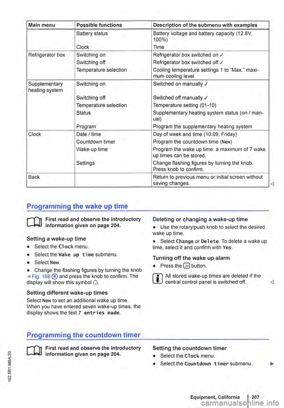
Main menu Possible functions
Battery status
Clock
Refrigerator box Switching on
Switching off
Temperature selection
Supplementary Switching on heating system
Switching off
Temperature selection
Status
Program
Clock Date I time
Countdown timer
Wake-up time
Settings
Back
Programming the wake up time
r--f"'n First read and observe the introductory L-lo::.U information given on page 204.
Setting a wake-up time
• Select the Clock menu.
• Select the Wake up time submenu.
• Select New.
• Change the flashing figures by turning the knob 168@ and press the knob to confirm. The display will show this symbol 0.
Setting different wake-up times
Select New to set an additional wake up time. When you have entered seven wake-up times, the display shows the text 7 entries made.
Programming the countdown timer
r--f"'n First read and observe the introductory L-lo::.U information given on page 204.
Description of the submenu with examples
Battery voltage and battery capacity (12.8V, 100%)
Time
Refrigerator box switched on .t
Refrigerator box switched off ./
Cooling temperature settings 1 to "Max." maxi-mum cooling level
Switched on manually .;
Switched off manually .;
Temperature setting (01-10)
Supplementary heating system status (on I man-ual)
Program the supplementary heating system
Day of week and time (10:09. Friday)
Program the countdown time (New)
Program the wake up time: a maximum of 7 wake up times can be stored.
Change flashing figures by turning the knob. Press knob to confirm.
Return to previous menu or initial screen without saving changes.
Deleting or changing a wake-up time
• Use the rotary/push knob to select the desired wake up time.
• Select Change or Del et e. To delete a wake up time, select it and confirm with Yes.
Turning off the wake up alarm
• Press button.
r::l All stored wake-up times are deleted if the L!J central control panel is switched off.
Setting the countdown timer
• Select the Clock menu.
• Select the Countdown timer submenu.
Equipment, California I 207
Page 225 of 486
Closing the electric pop-up roof manually
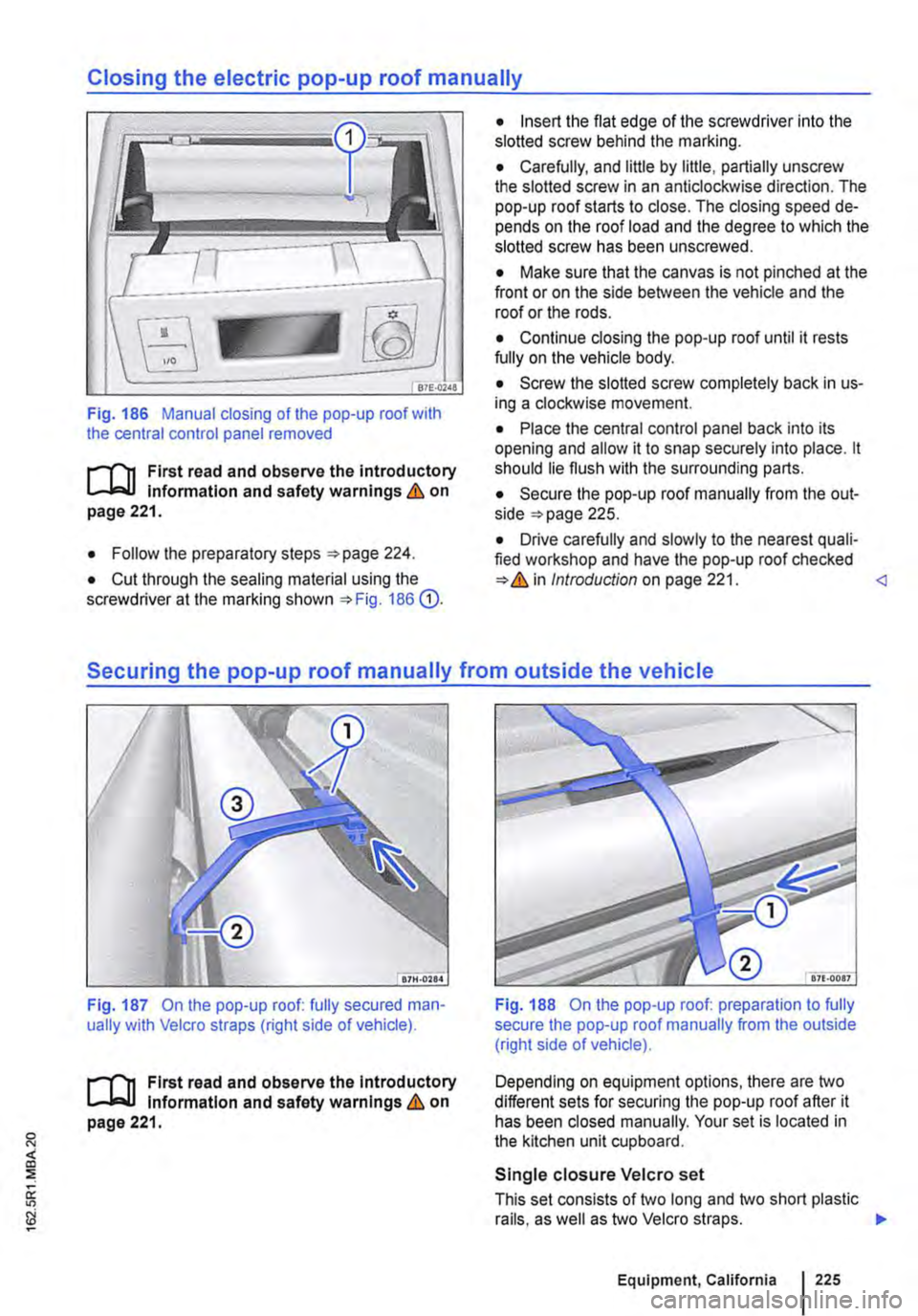
Fig. 186 Manual closing of the pop-up roof with the central control panel removed
t'""('n First read and observe the introductory Information and safety warnings & on page 221.
• Follow the preparatory steps 224.
• Cut through the sealing material using the screwdriver at the marking shown 186 G).
• Insert the flat edge of the screwdriver into the slotted screw behind the marking.
• Carefully, and little by little, partially unscrew the slotted screw in an anticlockwise direction. The pop-up roof starts to close. The closing speed de-pends on the roof load and the degree to which the slotted screw has been unscrewed.
• Make sure that the canvas is not pinched at the front or on the side between the vehicle and the roof or the rods.
• Continue closing the pop-up roof until it rests fully on the vehicle body.
• Screw the slotted screw completely back in us-ing a clockwise movement.
• Place the central control panel back into its opening and allow it to snap securely into place. lt should lie flush with the surrounding parts.
• Secure the pop-up roof manually from the out-side 225.
• Drive carefully and slowly to the nearest quali-fied workshop and have the pop-up roof checked Introduction on page 221.
Fig. 187 On the pop-up roof: fully secured man-ually with Velcro straps (right side of vehicle).
t'""('n First read and observe the Introductory Information and safety warnings & on page 221.
Fig. 188 On the pop-up roof: preparation to fully secure the pop-up roof manually from the outside (right side of vehicle).
Depending on equipment options, there are two different sets for securing the pop-up roof after it has been closed manually. Your set is located in the kitchen unit cupboard.
Single closure Velcro set
This set consists of two long and two short plastic rails, as well as two Velcro straps. .,.
Equipment, California 225
Page 250 of 486

A WARNING (Continued)
• Never fit fuses that have a higher fuse pro-tection limit. Fuses must always be replaced by a new fuse with the same amp rating (same colour and markings) and size.
• Never repair a fuse.
• Never use a metal strip, paper clip or simi-lar objects to replace a fuse.
CD
• To avoid damage to the electrical system in the vehicle, switch the ignition, the lights and all electrical consumers off and remove the ve-hicle key from the ignition before changing a fuse.
• You can damage another position in the electrical system by using a fuse with a higher amp rating.
• Fuse boxes must be protected from dirt and moisture when opened. Dirt and moisture in the fuse boxes can damage the electrical system.
o::n Introduction
This chapter contains information on the following subjects:
Controls for the living area 250
Controls for the living area
Fig. 215 Controls for the Climatic
ifl1 First read and observe the introductory L-.J.=.IJ information given on page 250.
Depending on equipment options, your vehicle is fitted with one of the control units shown here for the living area.
250 I Before the journey
Additional information:
• Air conditioning system 322.
Fig. 216 Controls for the Climatronic
Climatic: heating the living area
• Turn the temperature control clockwise to set the required heating temperature 215 G).
• Turn the blower control @ to one of the set-tings 1-4.
Page 337 of 486
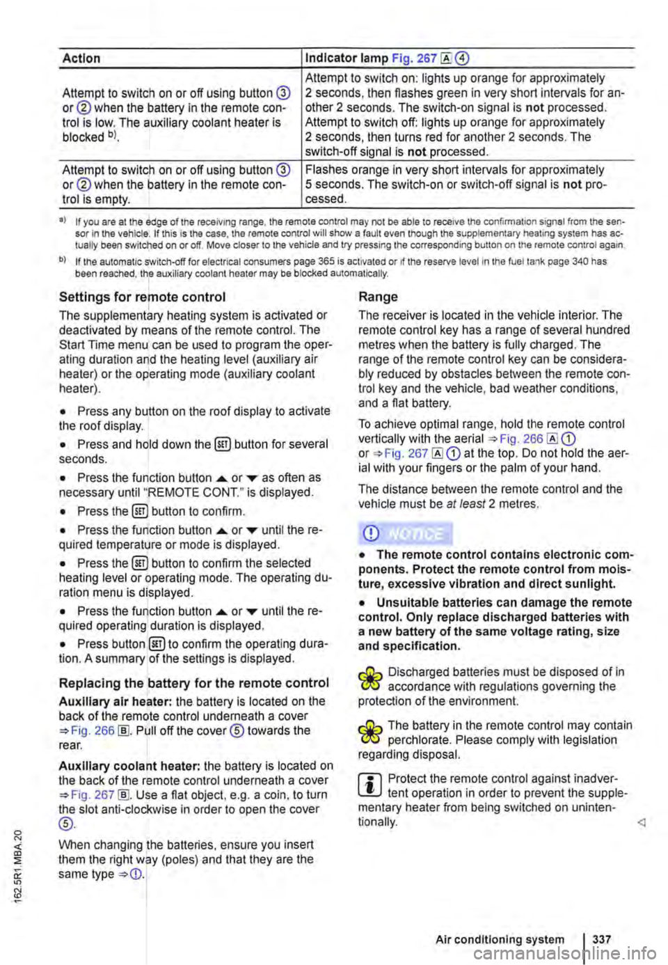
Action Indicator lamp Fig. 267
Attempt to switch on: lights up orange for approximately Attempt to switch on or off using button @ or@ when the battery in the remote con-trol is low. The auxiliary coolant heater is blocked bl.
2 seconds, then flashes green in very short intervals for an-other 2 seconds. The switch-on signal is not processed. Attempt to switch off: lights up orange for approximately 2 seconds, then turns red for another 2 seconds. The switch-off signal is not processed.
Attempt to switch on or off using button @ or@ when the battery in the remote con-trol is empty.
Flashes orange in very short intervals for approximately 5 seconds. The switch-on or switch-off signal is not pro-cessed.
•> If you are at the edge of the receiving range, the remote control may not be able to receive the confirmation signal from the sen-sor in the vehicle. If this is the case, the remote control will show a fault even though the supplementary heating system has ac-tually been switched on or off. Move closer to the vehicle and try pressing the corresponding button on the remote control again.
b) If the automatic switch-off for electrical consumers page 365 is activated or if the reserve level in lhe fuel tank page 340 has been reached, the auxiliary coolant heater may be blocked automatically.
Settings for remote control
The supplementary heating system is activated or deactivated by means of the remote control. The Start Time menu can be used to program the oper-ating duration and the heating level (auxiliary air heater) or the operating mode (auxiliary coolant heater).
• Press any button on the roof display to activate the roof display.
• Press and hold down the (ill) button for several seconds.
• Press the function button ...... or ,... as often as necessary until "REMOTE CONT." is displayed.
• Press the (ill) button to confirm.
• Press the function button ...... or ,... until the re-quired temperature or mode is displayed.
• Press the (ill) button to confirm the selected heating level or operating mode. The operating du-ration menu is displayed.
• Press the function button ...... or ,... until the re-quired operating duration is displayed.
• Press button @)to confirm the operating dura-tion. A summary of the settings is displayed.
Replacing the battery for the remote control
Auxiliary air heater: the battery is located on the back of the remote control underneath a cover 266 [ID. Pull off the cover® towards the rear.
Auxiliary coolant heater: the battery is located on the back of the remote control underneath a cover 267 [ID. Use a flat object, e.g. a coin, to turn the slot anti-clockwise in order to open the cover
®-
When changing the batteries, ensure you insert them the right way (poles) and that they are the same type
Range
The receiver is located in the vehicle interior. The remote control key has a range of several hundred metres when the battery is fully charged. The range of the remote control key can be considera-bly reduced by obstacles between the remote con-trol key and the vehicle, bad weather conditions, and a flat battery.
To achieve optimal range, hold the remote control vertically with the aerial 266 or 267 at the top. Do not hold the aer-ial with your fingers or the palm of your hand.
The distance between the remote control and the vehicle must be at least 2 metres.
CD
• The remote control contains electronic com-ponents. Protect the remote control from mois-ture, excessive vibration and direct sunlight.
• Unsuitable batteries can damage the remote control. Only replace discharged batteries with a new battery of the same voltage rating, size and specification.
Discharged batteries must be disposed of in W accordance with regulations governing the protection of the environment.
The battery in the remote control may contain W perchlorate. Please comply with legislation regarding disposal.
m Protect the remote control against inadver-L!.J tent operation in order to prevent the supple-mentary heater from being switched on uninten-
Air conditioning system I 337
Page 425 of 486
• Clean the area around the fastening holes of the spare wheel.
• Position the spare wheel.
• Insert the anti-theft wheel bolt using the adapter at position 298 @or® and tighten it slight-ly.
• Screw in all the other wheel bolts in a clockwise direction and use the box spanner to tighten them gently.
• Lower the vehicle with the jack.
• Use the box spanner to tighten all the wheel bolts securely in a clockwise direction &. Do not tighten the bolts in clockwise or anticlockwise se-quence. Tighten them in diagonal sequence.
• Fit the cover caps, centre covers or wheel cov-ers 417.
After changing a wheel
rl'l1 First read and observe the Introductory L-.lo:.ll Information and safety warnings & on page 420.
• If necessary, clean the vehicle tools and stow them safely in the vehicle 416.
• Stow the spare wheel or the removed wheel safely under the vehicle.
Breakdown set
CQJ Introduction
This chapter contains information on the following subjects:
Storing . . . . . . . . . . . . . . . . . . . . 426
Contents of the breakdown set . . . . . . . . . . . . 427 Preparation . . . . . . . . . . . . . . . . . . . . . . . . . . . 427
Sealing and inflating tyres . . . . • . . . . . . . 428
Test after driving for 10 minutes . . . . 429
You can use the breakdown set (tyre mobility set) to safely seal any tyre damage caused by foreign bodies or punctures (up to 4 mm (0.16 Inches) in diameter). Do not remove foreign objects (e.g. screws or nails) from the tyrel
Once the sealant has been added to the tyre, the tyre pressure must be checked again after approxi-mately 10 minutes of driving.
,A WARNING
Incorrect torque or incorrect use of wheel bolts can lead to a loss of control of the vehi-cle, cause accidents and serious Injuries.
• Always keep all wheel bolts and threads In the wheel hubs clean and free from oil and grease. The wheel bolts must be easy to turn and be tightened to the specified torque.
• The hexagonal socket In the screwdriver handle should only be used for turning wheel bolts, not use for loosening or tightening them.
• The damaged wheel should be replaced as soon as possible.
m In vehicles with a tyre monitoring system, the L!..J system may have to "re-learn" if new tyres are fitted 318.
Only use the breakdown set if the car is parked in a safe place, you are familiar with the required ac-tions and safety procedures, and you have access to the correct breakdown set. Seek expert assis-tance if this is not the case.
The tyre sealant must not be used:
• If the rim is damaged.
• If the outside temperature is below -2o•c (-4 ·F).
• If there are cuts or punctures in the tyre that are larger than 4 mm. .,.
Practical tips 425
Page 428 of 486
A WARNING (Continued)
• Always follow the instructions In the checklist and observe the general safety pro-
Sealing and inflating tyres
r-"'('n First read and observe the Introductory L-J,.:.U Information and safety warnings & on page 425.
Sealing a tyre
• Unscrew the cap from the tyre valve.
• Use the valve core extractor 302 CD to screw the valve core out of the tyre valve. Place the core on a clean surface.
• Shake the tyre filler bottle 302 ® vigo-rously up and down several times.
• Screw the filler hose 302 @tightly onto the tyre filler bottle in a clockwise direction. The plastic foil on the plug is pierced automatically.
• Remove the plug from the filler hose 302@ and place the open end fully on the tyre valve.
• Hold the bottle upside down and inject the en-tire contents of the tyre filler bottle into the tyre.
• Remove the empty tyre filler bottle from the valve.
• Use the valve core extractor 302 CD to screw the valve core back onto the tyre valve.
Inflating the tyre
• Screw the tyre filler hose 302 ® of the air compressor tightly onto the tyre valve.
• Check that the bleed screw 302 (?) is closed.
• Start the engine and let it run.
• Insert the plug 302 ®into one of the ve-hicle's 12-volt sockets 163.
• Use the on/off switch 302 ®to switch on the air compressor.
• Run the compressor until the tyre pressure has reached 2.0-2.5 bar (29-36 psi I 200-250 kPa) maximum running time is 6 minutes
• Switch off the air compressor.
• If a pressure level of 2.0-2.5 bar (29-36 psi I 200 -250 kPa) cannot be achieved unscrew the tyre filler hose from the tyre valve.
428 I If and when
• Drive (or reverse) the vehicle approximately 1 0 metres so that the sealing compound is more evenly distributed in the tyre.
• Screw the tyre filler hose for the air compressor firmly back onto the tyre valve and inflate the tyre again.
• If the required pressure still cannot be reached, the tyre is too badly damaged. The tyre cannot be sealed with the breakdown set. Do not drive on. Seek expert assistance &.
• Disconnect the air compressor and unscrew the tyre filler hose from the tyre valve.
• Drive the vehicle no faster than 80 km/h (50 mph) once a tyre pressure of 2.0-2.5 bar (29-36 psi I 200-250 kPa) has been reached.
• Check the tyre pressure after driving for 10 mi-nutes 429.
A WARNING
The tyre filler hose and the air compressor can get hot during Inflation.
• Protect your hands and skin from the hot components.
• Do not place the hot tyre filler hose or the hot air compressor on any Inflammable mate-rials.
• Allow the device to cool down fully before stowing.
• If the tyre will not Inflate to at least 2.0 bar (29 psi/ 200 kPa), the tyre Is too damaged. The sealant Is unable to seal the tyre. Do not drive on. Seek expert assistance.
CD
Switch the air compressor off after a maximum of 6 minutes to avoid overheating. Let the air compressor cool down for a few minutes be-fore switching it back on.
Page 439 of 486

The actions should only be carried out in the specified order·
311 Turn signal bulb
1. Observe and follow the instructions on the checklist ""page 433.
2. Open the bonnet.&. 350.
3. Remove the seating cap Q).
4. Release the connector@, and pull it off the bulb holder.
5. Turn the bulb holder@ anticlockwise as far as it will go and pull it out to the rear along with the bulb.
6. Push the bulb slightly into the bulb holder, turn it anti-clockwise, and pull it out straight.
7. Replace the defective bulb with a new bulb of the same type (see the last line in the table "Bulbs").
8. Insert the bulb holder into the headlight and turn it clockwise as far as it will go.
9. Fit the sealing cap.
Bulb H21W
m The illustrations show the left-hand LED W headlight from behind. The right-hand LED headlight is a mirror image of the one shown.
Fig. 312 Changing the fog light bulb.
m First read and observe the introductory information and safety warnings & on page 432.
The actions should only be carried out in the specified order:
1. Follow the instructions on the checklist 433.
2.
3.
4.
5.
6.
When changing the right bulb, set the steering wheel to the left stop, and when chang-ing the left bulb, set the steering wheel to the right stop.
Use the screwdriver from the vehicle tool kit to open the service flap 312 Q) in the wheel housing liner.
Release the connector, and pull it off the bulb holder@.
Turn the bulb holder anticlockwise and pull it out towards the rear with the bulb.
Turn the new bulb holder with the same designation and working bulb clockwise to the original position until it clicks into place (see the last line in the table "Bulbs").
__ ___:7...:.. ___ ..::.sh...:.o:...:u:....ld::.....:.c:...:lic.::.k:....i:....nt.:..:.o-"p-'-la:....c:..:e...:.. ___
Practical tips 439
Page 448 of 486
Fitting the towing eye at front
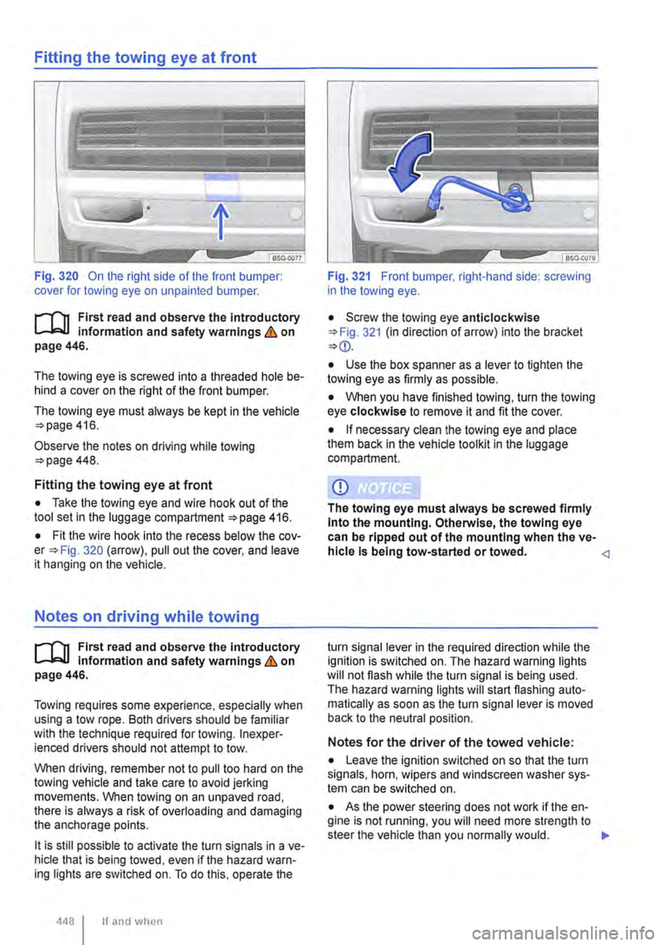
Fig. 320 On the right side of the front bumper: cover for towing eye on unpainted bumper.
l"""('n First read and observe the Introductory L-Jo:.U Information and safety warnings & on page 446.
The towing eye is screwed into a threaded hole be-hind a cover on the right of the front bumper.
The towing eye must always be kept in the vehicle 416.
Observe the notes on driving while towing 448.
Fitting the towing eye at front
• Take the towing eye and wire hook out of the tool set in the luggage compartment 416.
• Fit the wire hook into the recess below the cov-Fig. 320 (arrow). pull out the cover, and leave it hanging on the vehicle.
Notes on driving while towing
l"""('n First read and observe the introductory L-Jo:.U Information and safety warnings & on page 446.
Towing requires some experience, especially when using a tow rope. Both drivers should be familiar with the technique required for towing. lnexper· ienced drivers should not attempt to tow.
When driving, remember not to pull too hard on the towing vehicle and take care to avoid jerking movements. When towing on an unpaved road, there is always a risk of overloading and damaging the anchorage points.
lt is still possible to activate the turn signals in a ve-hicle that is being towed, even if the hazard warn-ing lights are switched on. To do this, operate the
4481 If and when
Fig. 321 Front bumper. right-hand side: screwing in the towing eye.
• Screw the towing eye anticlockwise 321 (in direction of arrow) into the bracket
• Use the box spanner as a lever to tighten the towing eye as firmly as possible.
• When you have finished towing, turn the towing eye clockwise to remove it and fit the cover.
• If necessary clean the towing eye and place them back in the vehide toolkit in the luggage compartment.
CD
The towing eye must always be screwed firmly Into the mounting. Otherwise, the towing eye can be ripped out of the mounting when the ve-hicle Is being tow-started or towed.
Notes for the driver of the towed vehicle:
• Leave the ignition switched on so that the turn signals, horn, wipers and windscreen washer sys-tem can be switched on.
• As the power steering does not work if the en-gine is not running, you will need more strength to steer the vehicle than you normally would. .,.