2019 VOLKSWAGEN TRANSPORTER low beam
[x] Cancel search: low beamPage 146 of 486
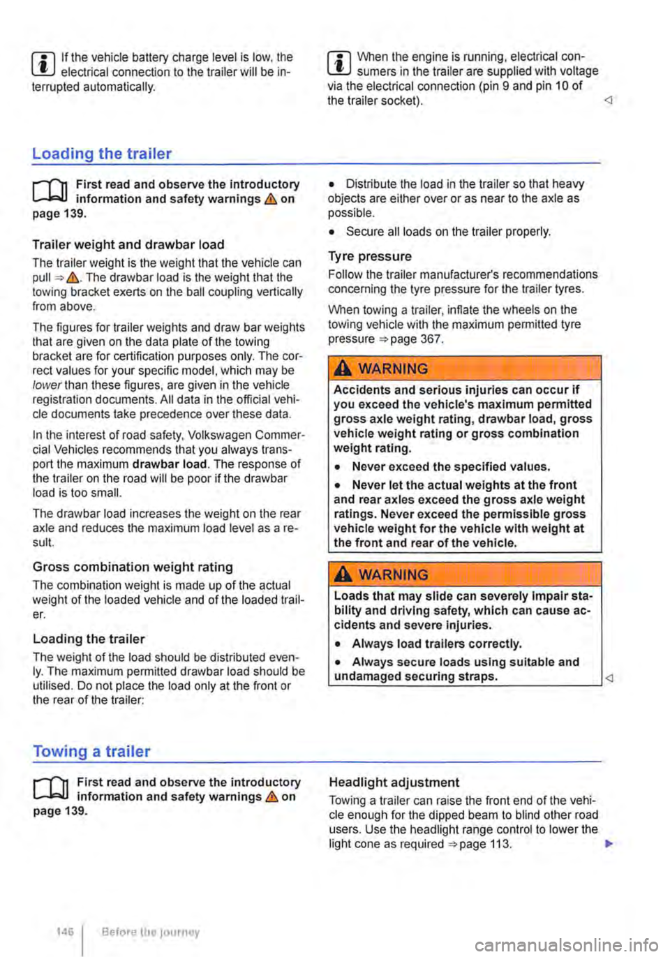
m If the vehicle battery charge level is low, the W electrical connection to the trailer will be in-terrupted automatically.
Loading the trailer
ill1 First read and observe the introductory L-W.! information and safety warnings & on page 139.
Trailer weight and drawbar load
The trailer weight is the weight that the vehicle can pull &. The drawbar load is the weight that the towing bracket exerts on the ball coupling vertically from above.
The figures for trailer weights and draw bar weights that are given on the data plate of the towing bracket are for certification purposes only. The cor-rect values for your specific model, which may be lower than these figures, are given in the vehicle registration documents. All data in the official vehi-cle documents take precedence over these data.
In the interest of road safety, Volkswagen Commer-cial Vehicles recommends that you always trans-port the maximum drawbar load. The response of the trailer on the road will be poor if the drawbar load is too small.
The drawbar load increases the weight on the rear axle and reduces the maximum load level as a re-sult.
Gross combination weight rating
The combination weight is made up of the actual weight of the loaded vehicle and of the loaded trail-er.
Loading the trailer
The weight of the load should be distributed even-ly. The maximum permitted drawbar load should be utilised. Do not place the load only at the front or the rear of the trailer:
Towing a trailer
ill1 First read and observe the introductory L-W.! information and safety warnings & on page 139.
146 Before the Journey
m When the engine is running, electrical con-w sumers in the trailer are supplied with voltage via the electrical connection (pin 9 and pin 10 of the trailer socket).
• Secure all loads on the trailer properly.
Tyre pressure
Follow the trailer manufacturer's recommendations concerning the tyre pressure for the trailer tyres.
When towing a trailer, inflate the wheels on the towing vehicle with the maximum permitted tyre pressure 367.
A WARNING
Accidents and serious injuries can occur if you exceed the vehicle's maximum permitted gross axle weight rating, drawbar load, gross vehicle weight rating or gross combination weight rating.
• Never exceed the specified values .
• Never let the actual weights at the front and rear axles exceed the gross axle weight ratings. Never exceed the permissible gross vehicle weight for the vehicle with weight at the front and rear of the vehicle.
A wARNING
Loads that may slide can severely Impair sta-bility and driving safety, which can cause ac-cidents and severe injuries.
• Always load trailers correctly .
• Always secure loads using suitable and undamaged securing straps.
Headlight adjustment
Towing a trailer can raise the front end of the vehi-cle enough for the dipped beam to blind other road users. Use the headlight range control to lower the
Page 343 of 486

Capacities
r--('n First read and observe the introductory L-W.I information and safety warnings & on page 340.
Checks when filling the tank
r--r'n First read and observe the introductory L-W.I information and safety warnings & on page 340.
Checklist
Never carry out any work on the engine or in the engine compartment if you are not familiar with the necessary procedures and the general safety re-quirements or if the correct operating equipment, fluids and unsuitable tools are not available 350, Preparation for working in the engine compartment! The work should be carried out by a qualified workshop if you are uncertain. Please en-sure that the following are checked regular1y, pref-erably every time you fill the tank:
..( Windscreen washer fluid level 116
..( Engine oil level 353
Fuel
c:QJ Introduction
This chapter contains information on the following subjects:
Petrol
Diesel ...
344 345
Different engines require different fuels. The facto-ry-fitted sticker on the inside of the tank flap indi-cates the fuel type that is required for your particu-lar vehicle.
Volkswagen Commercial Vehicles recommends us-ing fuels with a low sulphur content or which are sulphur-free in order to reduce fuel consumption and prevent damage to the engine.
If the engine is not running smoothly or begins to judder, this can indicate poor or inadequate fuel quality, e.g. water in the fuel. If these symptoms appear, reduce the vehicle speed immediately and drive to the nearest qualified workshop at medium engine speeds, avoiding high engine loading. If these symptoms occur immediately after the vehi-
Fuel tank capacity
Approx. 80.0 I,
..( Engine coolant level 358
..( Brake fluid level 269
..( Tyre pressure 367
..( Vehicle lighting necessary for traffic safety:
-Turn signals
-Side lights, dipped beam headlights and main beam headlights
-Tail light cluster
-Brake lights
-Rear fog light 1 08
Information on changing bulbs 432.
cle has been refuelled, switch the engine off as soon as it is safe to do so and seek expert assis-tance. This can help to prevent further damage.
Additional information and warnings:
• Filling the tank 340
• Engine management system and exhaust puri-fication system 407
• Service schedule
A WARNING
Incorrect handling of fuel can cause explo-sions, fire, serious burns and other injuries.
• Fuel is highly explosive and inflammable.
• Never handle fuel near open flames, sparks or glowing matter (e.g. cigarettes).
• Keep naked flames, hot parts and sparks at a safe distance.
At the filling station 1343
Page 411 of 486
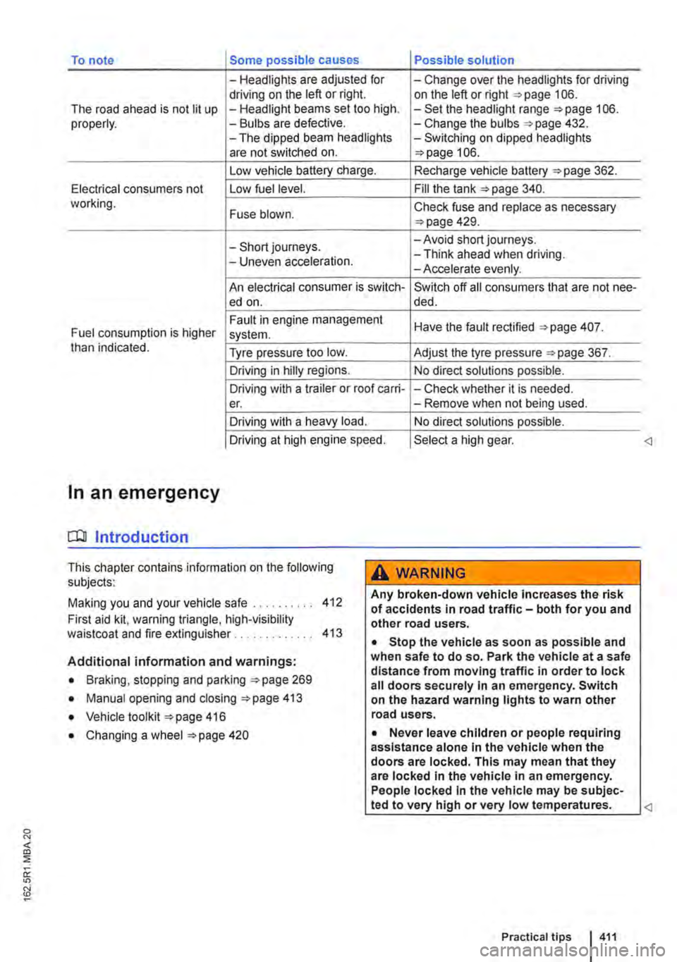
To note Some possible causes Possible solution
-Headlights are adjusted for -Change over the headlights for driving driving on the left or right. on the left or right 106. The road ahead is not lit up -Headlight beams set too high. -Set the headlight range 106. properly. -Bulbs are defective. -Change the bulbs 432. -The dipped beam headlights -Switching on dipped headlights are not switched on. 106.
Low vehicle battery charge. Recharge vehicle battery 362.
Electrical consumers not Low fuel level. Fill the tank 340. working. Fuse blown. Check fuse and replace as necessary 429.
-Short journeys. -Avoid short journeys.
-Uneven acceleration. -Think ahead when driving. -Accelerate evenly.
An electrical consumer is switch-Switch off all consumers that are not nee-ed on. de d.
Fault in engine management Have the fault rectified 407. Fuel consumption is higher system. than indicated. Tyre pressure too low. Adjust the tyre pressure 367.
Driving in hilly regions. No direct solutions possible.
Driving with a trailer or roof carri--Check whether it is needed. er. -Remove when not being used.
Driving with a heavy load. No direct solutions possible.
Driving at high engine speed. Select a high gear.
In an emergency
COl Introduction
This chapter contains information on the following subjects:
Making you and your vehicle safe . . 412
First aid kit. warning triangle, high-visibility waistcoat and fire extinguisher . . . . . . . . . . . . . 413
Additional information and warnings:
• Braking, stopping and parking 269
• Manual opening and closing 413
• Vehicle toolkit 416
• Changing a wheel 420
A WARNING
Any broken-down vehicle Increases the risk of accidents in road traffic-both for you and other road users.
• Stop the vehicle as soon as possible and when safe to do so. Park the vehicle at a safe distance from moving traffic In order to lock all doors securely In an emergency. Switch on the hazard warning lights to warn other road users.
• Never leave children or people requiring assistance alone In the vehicle when the doors are locked. This may mean that they are locked In the vehicle in an emergency. People locked In the vehicle may be subjec-
Page 434 of 486

Checklist (Continued)
3. Turn the light switch to position o 106.
4. Shift the tu m signal lever to neutral 106.
5. With a DSG® dual clutch gearbox, move the selector lever to position P 260.
6. Manual gearbox: select a gear 263.
7. Stop the engine and remove the key from the ignition 257.
8. Switch off the orientation lighting 106.
9. Leave the defective bulbs to cool down.
10. Check to see if a fuse has blown 429.
11. Follow the instructions to change the affec-ted bulb Always use identical bulbs of the same type. The designation is inscribed on the bulb, either on the glass part or on the base.
12. Do not touch the glass part of the bulb with unprotected fingers. The heat of the bulb would cause the fingerprint to evaporate and condense on the renector. This will im-pair the brightness of the headlight.
LED lights on the vehicle
r--f'n First read and observe the introductory L-I=J.I information and safety warnings & on page 432.
Depending on the vehicle equipment, the following lights may be LED lights:
• Dipped beam, main beam, daytime running lights and side lights on vehicles with LED head-lights.
• Tail light, brake light and fog light on vehicles with LED tail lights.
• Number plate lights.
434 If and when
13. After changing the bulb, check to ensure that the bulb is working properly. If the bulb is not working properly, the bulb may not have been inserted properly or may have failed again, or the connector may have been inserted incorrectly.
14. Any time you change a bulb in the front of the vehicle, the headlight settings should be checked by a qualified workshop.
A WARNING
Ignoring any of the items on this important safety checklist can lead to accidents and se-vere Injuries.
• Always follow the instructions in the checklist and observe the general safety pro-cedures.
CD
Always take care when removing or fitting lights in order to prevent damage to the paint-work or to other vehicle parts. <1
Owners cannot replace the LEDs themselves. If some LEDs fail, this may be an indication that more elements are on the point of failure. If this happens, have the lights checked and replaced if necessary at a qualified workshop.
Page 435 of 486
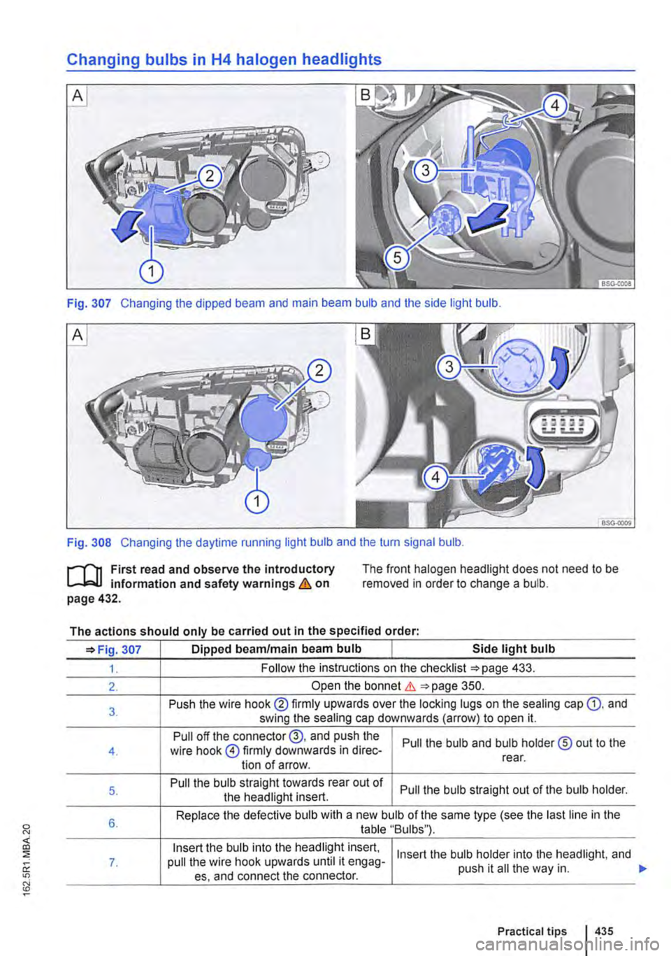
Changing bulbs in H4 halogen headlights
Fig. 307 Changing the dipped beam and main beam bulb and the side light bulb.
Fig. 308 Changing the daytime running light bulb and the turn signal bulb.
r-f"'n First read and observe the introductory L-J.::.l.l information and safety warnings & on page 432.
The front halogen headlight does not need to be removed in order to change a bulb.
The actions should only be carried out in the specified order:
307 Dipped beam/main beam bulb Side light bulb
1. Follow the instructions on the checklist 433.
2. Open the bonnet & 350.
3. Push the wire hook® firmly upwards over the locking lugs on the sealing cap Q). and swing the sealing cap downwards (arrow) to open it.
Pull off the connector@, and push the Pull the bulb and bulb holder® out to the 4. wire hook @firmly downwards in direc-tion of arrow. rear.
5. Pull the bulb straight towards rear out of Pull the bulb straight out of the bulb holder. the headlight insert.
6. Replace the defective bulb with a new bulb of the same type (see the last line in the table "Bulbs"}.
Insert the bulb into the headlight insert, Insert the bulb holder into the headlight, and 7. pull the wire hook upwards until it engag-push it ail the way in. es, and connect the connector.
Practical tips 435
Page 436 of 486
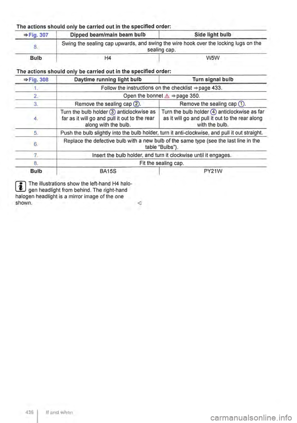
The actions should only be carried out in the specified order:
=>Fig. 307 Dipped beam/main beam bulb Side light bulb
8.
Bulb
Swing the sealing cap upwards, and swing the wire hook over the locking lugs on the sealing cap.
H4 W5W
The actions should only be carried out In the specified order·
=>Fig. 308 Daytime running light bulb Turn signal bulb
1. Follow the instructions on the checklist =>page 433.
2. Open the bonnet &. =>page 350.
3. Remove the sealing cap@. Remove the sealing cap Q).
Turn the bulb holder® anticlockwise as Turn the bulb holder@ anticlockwise as far 4. far as it will go and pull it out to the rear as it will go and pull it out to the rear along along with the bulb. with the bulb.
5. Push the bulb slightly into the bulb holder, turn it anti-clockwise, and pull it out straight.
6. Replace the defective bulb with a new bulb of the same type (see the last line in the table "Bulbs").
7. Insert the bulb holder, and turn it clockwise until it engages.
8. Fit the sealing cap.
Bulb BA15S I PY21W
m The illustrations show the left-hand H4 halo-L.!J gen headlight from behind. The right-hand halogen headlight is a mirror image of the one shown.
Page 437 of 486
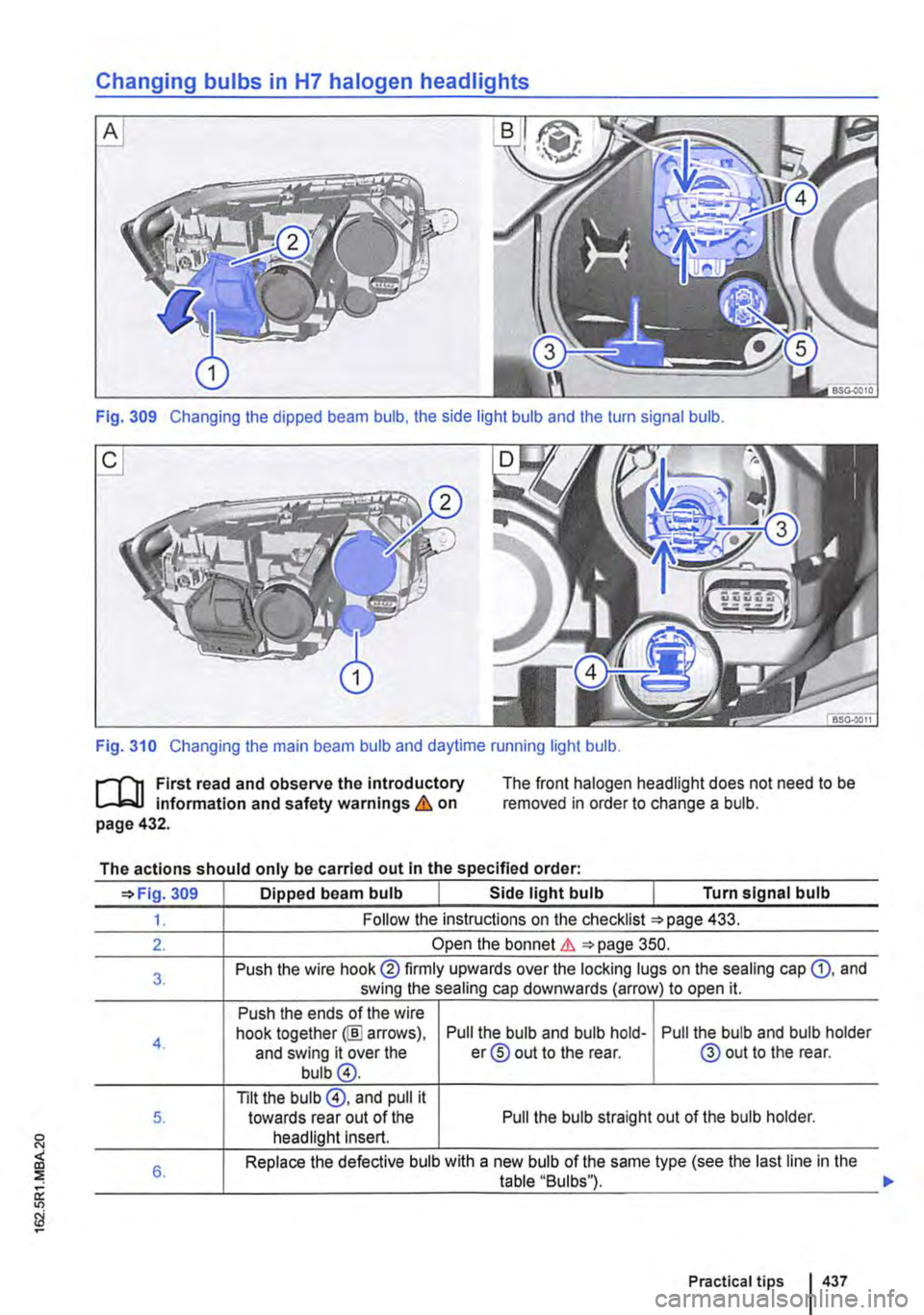
Changing bulbs in H7 halogen headlights
Fig. 309 Changing the dipped beam bulb, the side light bulb and the turn signal bulb.
Fig. 310 Changing the main beam bulb and daytime running light bulb.
l""""'('n First read and observe the introductory L-Jo:.Jl information and safety warnings & on page 432.
The front halogen headlight does not need to be removed in order to change a bulb.
The actions should only be carried out in the specified order:
=>Fig. 309 Dipped beam bulb Side light bulb Turn signal bulb
1. Follow the instructions on the checklist =>page 433.
2. Open the bonnet&. =>page 350.
3. Push the wire hook@ firmly upwards over the locking lugs on the sealing cap G), and swing the sealing cap downwards (arrow) to open it.
Push the ends of the wire
4. hook together@] arrows), Pull the bulb and bulb hold-Pull the bulb and bulb holder and swing it over the er® out to the rear. @out to the rear. bulb@.
Tilt the bulb @, and pull it 5. towards rear out of the Pull the bulb straight out of the bulb holder. headlight Insert.
6. Replace the defective bulb with a new bulb of the same type (see the last line in the table "Bulbs").
Practical tips I 437
Page 438 of 486
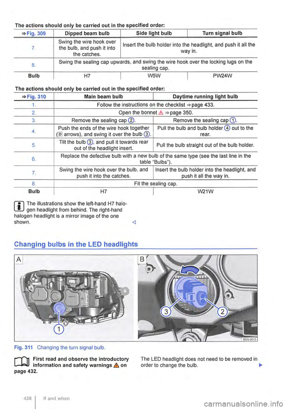
The actions should only be carried out in the specified order:
=>Fig. 309 Dipped beam bulb Side light bulb I Turn signal bulb
7
8.
Bulb
Swing the wire hook over the bulb, and push it into the catches.
Insert the bulb holder into the headlight, and push it all the way in.
Swing the sealing cap upwards, and swing the wire hook over the locking lugs on the sealing cap.
H7 I W5W I PW24W
The actions should only be carried out in the specified order·
=>Fig. 310 Main beam bulb Daytime running light bulb
1. Follow the instructions on the checklist =>page 433.
2. Open the bonnet Lh =>page 350.
3. Remove the sealing cap®. Remove the sealing cap G).
4. Push the ends of the wire hook together @I arrows), and swing it over the bulb @. Pull the bulb and bulb holder@ out to the rear.
5. Tilt the bulb@, and pull it towards rear Pull the bulb straight out of the bulb holder. out of the headlight insert.
6. Replace the defective bulb with a new bulb of the same type (see the last line in the table "Bulbs").
7. Swing the wire hook over the bulb, and Insert the bulb holder into the headlight, and push it into the catches. push it all the way in.
8. Fit the sealing cap.
Bulb H7
m The illustrations show the left-hand H7 halo-l!J gen headlight from behind. The right-hand halogen headlight is a mirror image of the one shown.
Fig. 311 Changing the turn signal bulb.
1"'"""111 First read and observe the introductory L-J,:.JJ information and safety warnings & on page 432.
438 I If and when
I W21W
The LED headlight does not need to be removed in order to change the bulb. .,..