Page 173 of 348

If it’s necessary to keep the ball mount and hitch ball
assembly mounted for a long period, it is possible to filter
out the ball mount and hitch ball assembly presence in
sensor field of view. The filtering operation must be
performed only by an authorized dealer.
PARKVIEW REAR BACK UP CAMERA
Your vehicle is equipped with the ParkView Rear Back Up
Camera that allows you to see an on-screen image of the rear
surroundings of your vehicle whenever the gear selector is
put into REVERSE. The image will be displayed on the
touchscreen display along with a caution note to “check
entire surroundings” across the top of the screen. After five
seconds this note will disappear. The ParkView camera is
located on the rear of the vehicle above the rear license plate.
The Rear Back Up Camera can also be activated when the
vehicle is not in REVERSE through the Uconnect System.
Refer to “Uconnect Settings” in “Multimedia” for further
information.
NOTE:If one of the rear cargo doors is not completely
closed, the Back Up Camera cannot provide an accurate
image of the area behind the vehicle. A dedicated message
will appear on the Uconnect display indicating the camera
is not in the correct position. The Camera Delay setting can be set to on/off in the rear
camera settings menu. When the vehicle is shifted out of
REVERSE and the Camera Delay is turned off, the rear
camera mode is exited and the navigation or audio screen
appears on display again.
When the transmission is shifted out of REVERSE, and
Camera Delay is activated in the menu screen, the camera
image will continue to be displayed for up to 10 seconds,
unless the speed of the vehicle is greater than 8 mph
(13 km/h), the transmission is in PARK, or the ignition key
is in the OFF position.
When displayed, static grid lines will illustrate the width of
the vehicle and will show separate zones that will help
indicate the distance to the rear of the vehicle. The follow-
ing table shows the approximate distances for each zone:
Zone
Distance To The Rear Of The
Vehicle
Red 0 - 1 ft (0 - 30 cm)
Yellow 1 ft - 3 ft (30 cm - 1 m)
Green 3 ft or greater (1 m or greater)
6
STARTING AND OPERATING 171
Page 179 of 348

The tongue weight is the downward force exerted on the
hitch ball by the trailer. You must consider this as part of
the load on your vehicle.
Trailer Frontal Area
The frontal area i")
Tongue Weight (TW)
The tongue weight is the downward force exerted on the
hitch ball by the trailer. You must consider this as part of
the load on your vehicle.
Trailer Frontal Area
The frontal area is the maximum height multiplied by the
maximum width of the front of a trailer.
Trailer Sway Control
The trailer sway control can be a mechanical telescoping
link that can be installed between the hitch receiver and the
trailer tongue that typically provides adjustable friction
associated with the telescoping motion to dampen any
unwanted trailer swaying motions while traveling.
If equipped, the electronic Trailer Sway Control (TSC)
recognizes a swaying trailer and automatically applies
individual wheel brakes and/or reduces engine power to
attempt to eliminate the trailer sway.
Weight-Carrying Hitch
A weight-carrying hitch supports the trailer tongue weight,
just as if it were luggage located at a hitch ball or some
other connecting point of the vehicle. These kinds ofhitches are the most popular on the market today and they
are commonly used to tow small and medium sized
trailers.
Weight-Distributing Hitch
A weight-distributing system works by applying leverage
through spring (load) bars. They are typically used for
heavier loads to distribute trailer tongue weight to the tow
vehicle’s front axle and the trailer axle(s). When used in
accordance with the manufacturer’s directions, it provides
for a more level ride, offering more consistent steering and
brake control thereby enhancing towing safety. The addi-
tion of a friction/hydraulic sway control also dampens
sway caused by traffic and crosswinds and contributes
positively to tow vehicle and trailer stability. Trailer sway
control and a weight distributing (load equalizing) hitch
are recommended for heavier Tongue Weights (TW) and
may be required depending on vehicle and trailer
configuration/loading to comply with Gross Axle Weight
Rating (GAWR) requirements.
6
STARTING AND OPERATING 177
Page 259 of 348
 — Metric tire sizing is based on U.S.
design standards. P-Metric tires have the letter “P”
molded into the sidewall preceding the size designation.
Example: P")
Tire MarkingsNOTE:
•P (Passenger) — Metric tire sizing is based on U.S.
design standards. P-Metric tires have the letter “P”
molded into the sidewall preceding the size designation.
Example: P215/65R15 95H.
• European — Metric tire sizing is based on European
design standards. Tires designed to this standard have
the tire size molded into the sidewall beginning with the
section width. The letter �P�is absent from this tire size
designation. Example: 215/65R15 96H.
• LT (Light Truck) — Metric tire sizing is based on U.S.
design standards. The size designation for LT-Metric
tires is the same as for P-Metric tires except for the letters
“LT” that are molded into the sidewall preceding the
size designation. Example: LT235/85R16.
• Temporary spare tires are designed for temporary emer-
gency use only. Temporary high pressure compact spare
tires have the letter “T” or “S” molded into the sidewall
preceding the size designation. Example: T145/80D18
103M.
• High flotation tire sizing is based on U.S. design stan-
dards and it begins with the tire diameter molded into
the sidewall. Example: 31x10.5 R15 LT.
Tire Markings
1 — U.S. DOT Safety
Standards Code (TIN) 4 — Maximum Load
2 — Size Designation 5 — Maximum Pressure
3 — Service Description 6 — Treadwear, Traction
and Temperature Grades 8
SERVICING AND MAINTENANCE 257
Page 260 of 348
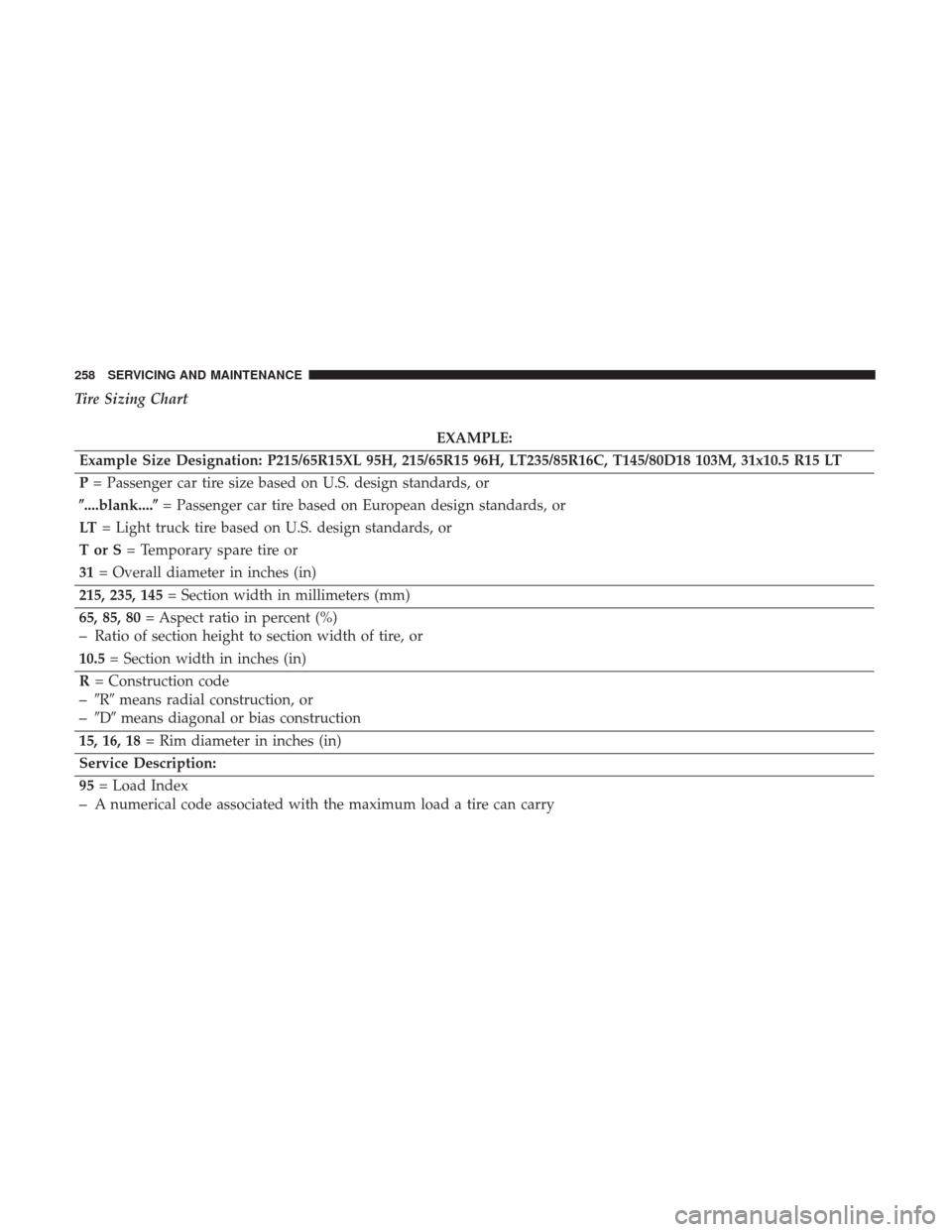
Tire Sizing Chart
EXAMPLE:
Example Size Designation: P215/65R15XL 95H, 215/65R15 96H, LT235/85R16C, T145/80D18 103M, 31x10.5 R15 LT
P = Passenger car tire size based on U.S. design standards, or
�....blank....� = Passenger car tire based on European design standards, or
LT = Light truck tire based on U.S. design standards, or
TorS= Temporary spare tire or
31 = Overall diameter in inches (in)
215, 235, 145 = Section width in millimeters (mm)
65, 85, 80 = Aspect ratio in percent (%)
–Ratio of section height to section width of tire, or
10.5 = Section width in inches (in)
R = Construction code
–�R� means radial construction, or
–�D� means diagonal or bias construction
15, 16, 18 = Rim diameter in inches (in)
Service Description:
95 = Load Index
–A numerical code associated with the maximum load a tire can carry
258 SERVICING AND MAINTENANCE