Page 218 of 348

Vehicles Equipped With Wheel Covers
1. Mount the road tire on the axle.
2. To ease the installation process for steel wheels withwheel covers, install two wheel bolts on the wheel.
Install the wheel bolts with the threaded end of the bolt
toward the wheel. Lightly tighten the wheel bolts. 3. Align the valve notch in the wheel cover with the valve
stem on the wheel. Install the cover by hand, snapping
the cover over the two wheel bolts. Do not use a
hammer or excessive force to install the cover.
4. Install the remaining wheel bolts with the threaded end of the wheel bolt toward the wheel. Lightly tighten the
wheel bolts.
WARNING!
To avoid the risk of forcing the vehicle off the jack, do
not fully tighten the wheel bolts until the vehicle has
been lowered. Failure to follow this warning may
result in serious injury.
5. Lower the vehicle to the ground by turning the jack handle counterclockwise.
6. Finish tightening the wheel bolts. Push down on the wrench while holding at the end of the handle for
increased leverage. Tighten the wheel bolts in a star
pattern until each wheel bolt has been tightened twice.
Refer to “Torque Specifications” in “Technical Specifica-
tions” for correct wheel bolt torque.
Tire And Wheel Cover Or Center Cap
1 — Valve Stem 4 — Wheel Cover
2 — Valve Notch 5 — Road Wheel
3 — Wheel Bolt 216 IN CASE OF EMERGENCY
Page 222 of 348

WARNING!
Store the sealant canister in its special compartment,
away from sources of heat. Failure to follow this
WARNING may result in sealant canister rupture and
serious injury or death.
JUMP STARTING
If your vehicle has a discharged battery, it can be jump
started using a set of jumper cables and a battery in another
vehicle or by using a portable battery booster pack. Jumpstarting can be dangerous if done improperly, so please
follow the procedures in this section carefully.
NOTE:
When using a portable battery booster pack, follow
the manufacturer ’s operating instructions and precautions.
WARNING!
Do not attempt jump starting if the battery is frozen. It
could rupture or explode and cause personal injury.
CAUTION!
Do not use a portable battery booster pack or any other
booster source with a system voltage greater than 12
Volts or damage to the battery, starter motor, alternator
or electrical system may occur.
Preparations For Jump Starting
The battery in your vehicle is located in the front of the
engine compartment, behind the left headlight assembly.
NOTE: The positive battery post is covered with a protec-
tive cap. Lift up on the cap to gain access to the positive
battery post.
Tire Service Kit Expiration Date Location
220 IN CASE OF EMERGENCY
Page 235 of 348

SCHEDULED SERVICING
Your vehicle is equipped with an automatic oil change
indicator system. The oil change indicator system will
remind you that it is time to take your vehicle in for
scheduled maintenance.
Based on engine operation conditions, the oil change
indicator message will illuminate. This means that service
is required for your vehicle. Operating conditions such as
frequent short-trips, trailer tow, extended engine idle time,
extremely hot or cold ambient temperatures will influence
when the “Oil Change Required” message is displayed.
Severe Operating Conditions can cause the change oil
message to illuminate as early as 3,500 miles (5,600 km)
since last reset. Have your vehicle serviced as soon as
possible, within the next 500 miles (805 km).
Your authorized dealer will reset the oil change indicator
message after completing the scheduled oil change. If a
scheduled oil change is performed by someone other than
your authorized dealer, the message can be reset by
referring to the steps described under “Oil Change Reset”
in “Instrument Cluster Display” in “Getting To Know Your
Instrument Panel” for further information.NOTE:
Under no circumstances should oil change inter-
vals exceed 10,000 miles (16,000 km), 350 hours of engine
run time or twelve months, whichever comes first. The 350
hours of engine run or idle time is generally only a concern
for fleet customers.
Severe Duty All Models
Change Engine Oil at 4,000 miles (6,500 km) or 350 hours of
engine run time if the vehicle is operated in a dusty and off
road environment or is operated predominantly at idle, or
only very low engine RPM’s. This type of vehicle use is
considered Severe Duty.
Once A Month Or Before A Long Trip:
• Check engine oil level.
• Check windshield washer fluid level.
• Check tire pressure and look for unusual wear or
damage. Rotate tires at the first sign of irregular wear,
even if it occurs before the oil indicator system turns on.
• Check the fluid levels of the coolant reservoir and brake
master cylinder, fill as needed.
• Check function of all interior and exterior lights.
8
SERVICING AND MAINTENANCE 233
Page 253 of 348

WARNING!
Riding the brakes can lead to brake failure and possi-
bly a collision. Driving with your foot resting or riding
on the brake pedal can result in abnormally high brake
temperatures, excessive lining wear, and possible
brake damage. You would not have your full braking
capacity in an emergency.
Brake Master Cylinder
The fluid in the master cylinder should be checked when
performing under hood services or immediately if the
“Brake Warning Light” is illuminated.
Be sure to clean the top of the master cylinder area before
removing the cap. If necessary, add fluid to bring the fluid
level up to the requirements described on the brake fluid
reservoir. With disc brakes, fluid level can be expected to
fall as the brake pads wear. Brake fluid level should be
checked when pads are replaced. However, low fluid level
may be caused by a leak and a checkup may be needed.
Use only manufacturer’s recommended brake fluid. Refer
to “Fluids And Lubricants” in “Technical Specifications”
for further information.
WARNING!
•Use only manufacturer’s recommended brake fluid.
Refer to “Fluids And Lubricants” in “Technical
Specifications” for further information. Using the
wrong type of brake fluid can severely damage your
brake system and/or impair its performance. The
proper type of brake fluid for your vehicle is also
identified on the original factory installed hydraulic
master cylinder reservoir.
• To avoid contamination from foreign matter or mois-
ture, use only new brake fluid or fluid that has been
in a tightly closed container. Keep the master cylin-
der reservoir cap secured at all times. Brake fluid in
a open container absorbs moisture from the air
resulting in a lower boiling point. This may cause it
to boil unexpectedly during hard or prolonged brak-
ing, resulting in sudden brake failure. This could
result in a collision.
• Overfilling the brake fluid reservoir can result in
spilling brake fluid on hot engine parts, causing the
brake fluid to catch fire. Brake fluid can also damage
painted and vinyl surfaces, care should be taken to
avoid its contact with these surfaces.
(Continued)
8
SERVICING AND MAINTENANCE 251
Page 256 of 348
Upfitter Connectors — If Equipped
The preparation connectors are to be only used by upfitters
This connector is located under the dash15 Way Vehicle Connector Functions and View
PIN
Function
1 Not Connected
2 Alternator System Charging In Process Sig- nal
3 Vehicle Speed Repetition (VSO)
4 Not Connected
5 Not Connected
6 Not Connected
7 Additional Courtesy Light
Connector Location
Connector Pin Numbers
254 SERVICING AND MAINTENANCE
Page 257 of 348
PINFunction
8
Courtesy Lights Negative Control (Dimmed)
9 Not Connected
10 Not Connected
11 Not Connected
12 Not Connected
13 Power Supply At Key On (+Ignition)
14 Not Connected
15 Not Connected This connector is supplied to the upfitter when the vehicle
is ordered with the applicable package.
2 Way Vehicle Connector Functions and View
PIN
Function
A Power Supply
B GND
Upfitter Connector
Connector Pins
8
SERVICING AND MAINTENANCE 255
Page 259 of 348
 — Metric tire sizing is based on U.S.
design standards. P-Metric tires have the letter “P”
molded into the sidewall preceding the size designation.
Example: P")
Tire MarkingsNOTE:
•P (Passenger) — Metric tire sizing is based on U.S.
design standards. P-Metric tires have the letter “P”
molded into the sidewall preceding the size designation.
Example: P215/65R15 95H.
• European — Metric tire sizing is based on European
design standards. Tires designed to this standard have
the tire size molded into the sidewall beginning with the
section width. The letter �P�is absent from this tire size
designation. Example: 215/65R15 96H.
• LT (Light Truck) — Metric tire sizing is based on U.S.
design standards. The size designation for LT-Metric
tires is the same as for P-Metric tires except for the letters
“LT” that are molded into the sidewall preceding the
size designation. Example: LT235/85R16.
• Temporary spare tires are designed for temporary emer-
gency use only. Temporary high pressure compact spare
tires have the letter “T” or “S” molded into the sidewall
preceding the size designation. Example: T145/80D18
103M.
• High flotation tire sizing is based on U.S. design stan-
dards and it begins with the tire diameter molded into
the sidewall. Example: 31x10.5 R15 LT.
Tire Markings
1 — U.S. DOT Safety
Standards Code (TIN) 4 — Maximum Load
2 — Size Designation 5 — Maximum Pressure
3 — Service Description 6 — Treadwear, Traction
and Temperature Grades 8
SERVICING AND MAINTENANCE 257
Page 260 of 348
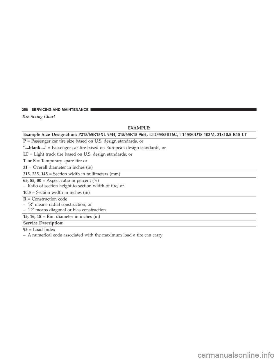
Tire Sizing Chart
EXAMPLE:
Example Size Designation: P215/65R15XL 95H, 215/65R15 96H, LT235/85R16C, T145/80D18 103M, 31x10.5 R15 LT
P = Passenger car tire size based on U.S. design standards, or
�....blank....� = Passenger car tire based on European design standards, or
LT = Light truck tire based on U.S. design standards, or
TorS= Temporary spare tire or
31 = Overall diameter in inches (in)
215, 235, 145 = Section width in millimeters (mm)
65, 85, 80 = Aspect ratio in percent (%)
–Ratio of section height to section width of tire, or
10.5 = Section width in inches (in)
R = Construction code
–�R� means radial construction, or
–�D� means diagonal or bias construction
15, 16, 18 = Rim diameter in inches (in)
Service Description:
95 = Load Index
–A numerical code associated with the maximum load a tire can carry
258 SERVICING AND MAINTENANCE


9 Not Connected
10 Not Connected
11 Not Connected
12 Not Connected
13 Power Supply At Key On (+Ignition)
14 Not Connected
15 Not Connected This")