Page 72 of 607
70 GETTING TO KNOW YOUR VEHICLE
Front Fog Lights — If Equipped
To activate the front fog lights, turn on the parking lights or
low beam headlights and push in the center of the headlight
switch control knob. Pushing the headlight switch control
knob a second time will turn the front fog lights off.Front Fog Light Switch
Turn Signals
Move the multifunction lever up or down and the arrows on
each side of the instrument cluster display will flash to show
proper operation of the front and rear turn signal lights.
NOTE:
If either light remains on and does not flash, or there is a very
fast flash rate, check for a defective outside light bulb. If an
indicator fails to light when the lever is moved, it would
suggest that the indicator bulb is defective.
Lane Change Assist — If Equipped
Tap the multifunction lever up or down once, without
moving beyond the detent, and the turn signal (right or left)
will flash three times then automatically turn off.
Page 83 of 607
GETTING TO KNOW YOUR VEHICLE 81
Climate Controls With A Touchscreen Overview
Uconnect 4/4C/4C NAV With 8.4–inch Display Automatic Temperature Controls
2
Page 84 of 607
82 GETTING TO KNOW YOUR VEHICLE
Uconnect 4C NAV With 12–inch Display Automatic Tem-
perature Controls Control Descriptions
NOTE:
Icons and descriptions can vary based upon vehicle equip
-
ment.
Page 87 of 607

GETTING TO KNOW YOUR VEHICLE 85
Driver and Passenger Temperature Up and Down Buttons
Provides the driver and passenger with independent temperature control. Push the red button on the
faceplate or touchscreen or press and slide the temperature bar towards the red arrow button on the
touchscreen for warmer temperature settings. Push the blue button on the faceplate or touchscreen or
press and slide the temperature bar towards the blue arrow button on the touchscreen for cooler
temperature settings.
NOTE:
The numbers within the temperature display will only appear if the system is equipped with an auto-
matic climate control system.
SYNC
Press the SYNC button on the touchscreen to toggle the SYNC feature on/off. The SYNC indicator is
illuminated when this feature is enabled. SYNC is used to synchronize the passenger temperature
setting with the driver temperature setting. Changing the passenger’s temperature setting while in
SYNC will automatically exit this feature.
NOTE:
The SYNC button is only available on the touchscreen.
Icon
Description
2
Page 88 of 607

86 GETTING TO KNOW YOUR VEHICLE
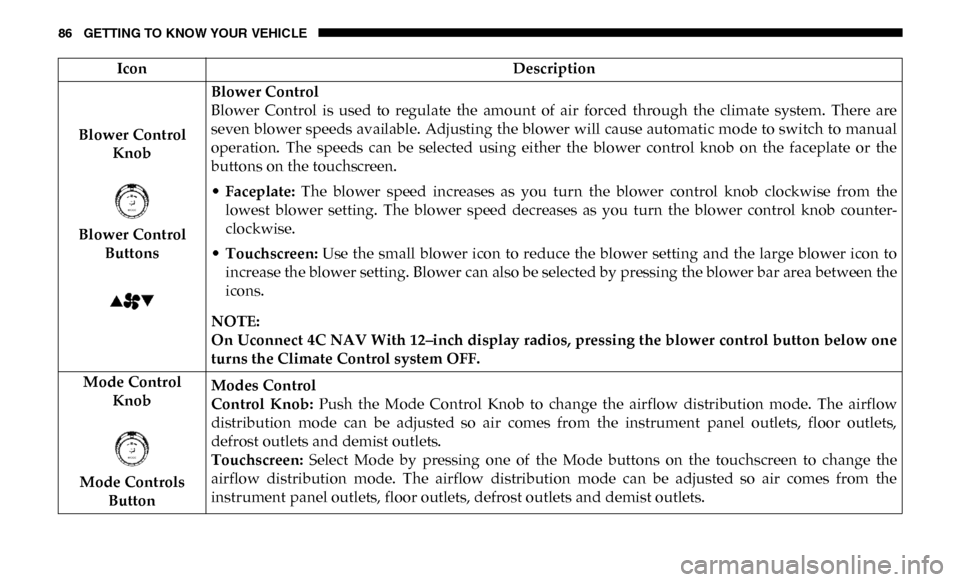
Blower Control Knob
Blower Control Buttons Blower Control
Blower Control is used to regulate the amount of air forced through the climate system. There are
seven blower speeds available. Adjusting the blower will cause automatic mode to switch to manual
operation. The speeds can be selected using either the blower control knob on the faceplate or the
buttons on the touchscreen.
•
Faceplate: The blower speed increases as you turn the blower control knob clockwise from the
lowest blower setting. The blower speed decreases as you turn the blower control knob counter -
clockwise.
• Touchscreen: Use the small blower icon to reduce the blower setting and the large blower icon to
increase the blower setting. Blower can also be selected by pressing the blower bar area between the
icons.
NOTE:
On Uconnect 4C NAV With 12–inch display radios, pressing the blower control button below one
turns the Climate Control system OFF.
Mode Control Knob
Mode Controls Button Modes Control
Control Knob:
Push the Mode Control Knob to change the airflow distribution mode. The airflow
distribution mode can be adjusted so air comes from the instrument panel outlets, floor outlets,
defrost outlets and demist outlets.
Touchscreen: Select Mode by pressing one of the Mode buttons on the touchscreen to change the
airflow distribution mode. The airflow distribution mode can be adjusted so air comes from the
instrument panel outlets, floor outlets, defrost outlets and demist outlets.
Icon
Description
Page 91 of 607

GETTING TO KNOW YOUR VEHICLE 89
Automatic Temperature Control (ATC)
Automatic Operation
1. Push the AUTO button on the faceplate, or the AUTObutton on the touchscreen on the Automatic Temperature
Control (ATC) Panel.
2. Next, adjust the temperature you would like the system to maintain by adjusting the driver and passenger
temperature control buttons. Once the desired tempera -
ture is displayed, the system will achieve and automati -
cally maintain that comfort level.
3. When the system is set up for your comfort level, it is not necessary to change the settings. You will experience the
greatest efficiency by simply allowing the system to func -
tion automatically.
NOTE:
• It is not necessary to move the temperature settings for cold or hot vehicles. The system automatically adjusts the
temperature, mode, and blower speed to provide comfort
as quickly as possible. • The temperature can be displayed in U.S. or Metric units
by selecting the US/Metric customer-programmable
feature. Refer to the “Uconnect Settings” in “Multimedia”
for further information.
To provide you with maximum comfort in the Automatic
mode during cold start-ups, the blower fan will remain on
low until the engine warms up. The blower will increase in
speed and transition into Auto mode.
Manual Operation Override
This system offers a full complement of manual override
features. The AUTO symbol in the front ATC display will be
turned off when the system is being used in the manual
mode.
Operating Tips
NOTE:
Refer to the chart at the end of this section for suggested
control settings for various weather conditions.
2
Page 126 of 607

124 GETTING TO KNOW YOUR INSTRUMENT PANEL
Base / Midline Instrument Cluster Descriptions
1. Tachometer• Indicates the engine speed in revolutions per minute(RPM x 1000).
2. Voltmeter
• When the vehicle is in the RUN state, the gauge indi -
cates the electrical system voltage. The pointer should
stay within the normal range if the battery is charged.
If the pointer moves to either extreme left or right and
remains there during normal driving, the electrical
system should be serviced.
3. Instrument Cluster Display
• When the appropriate conditions exist, this displayshows the instrument cluster display messages. Refer
to “Instrument Cluster Display” in “Getting To Know
Your Instrument Panel” for further information. 4. Oil Pressure Gauge
• The pointer should always indicate the oil pressurewhen the engine is running. A continuous high or low
reading under normal driving conditions may indicate
a lubrication system malfunction. Immediate service
should be obtained from an authorized dealer.
NOTE:
In vehicles equipped with Stop/Start, an oil pressure indica -
tion of zero is normal during an Autostop.
5. Speedometer
• Indicates vehicle speed.
Page 129 of 607

GETTING TO KNOW YOUR INSTRUMENT PANEL 127
Premium Instrument Cluster Descriptions
1. Tachometer• Indicates the engine speed in revolutions per minute(RPM x 1000).
2. Instrument Cluster Display
• When the appropriate conditions exist, this displayshows the instrument cluster display messages. Refer
to “Instrument Cluster Display” in “Getting To Know
Your Instrument Panel” for further information.
3. Speedometer
• Indicates vehicle speed.
4. Fuel Gauge
• The pointer shows the level of fuel in the fuel tankwhen the ignition is in the ON/RUN position.
• The fuel pump symbol points to the side of the vehicle where the fuel door is located. 5. Temperature Gauge
• The gauge pointer shows engine coolant temperature.The pointer positioned within the normal range indi -
cates that the engine cooling system is operating satis -
factorily.
• The gauge pointer will likely indicate a higher tempera -
ture when driving in hot weather, up mountain grades,
or when towing a trailer. It should not be allowed to
exceed the upper limits of the normal operating range.
WARNING!
A hot engine cooling system is dangerous. You or others
could be badly burned by steam or boiling coolant. You
may want to call an authorized dealer for service if your
vehicle overheats. If you decide to look under the hood
yourself, see “Servicing And Maintenance.” Follow the
warnings under the Cooling System Pressure Cap
paragraph.
3