2019 Peugeot Partner ESP
[x] Cancel search: ESPPage 186 of 312

184
For more information on the Warning
and indicator lamps and the associated
alerts, or the Indicators , refer to the
corresponding sections.
Freezing of the AdBlue
®
AdBlue® freezes at temperatures below
around -11°C.
The SCR system includes a heater for the
AdBlue
® tank, allowing you to continue
driving in very cold conditions.
Supply of AdBlue®
It is recommended that the AdBlue® is
topped up as soon as the first alert is
issued indicating that the reser ve level has
been reached.
In order to ensure that the SCR system
operates correctly:
-
U
se only AdBlue
® fluid that meets the
ISO 22241 standard.
-
N
ever transfer AdBlue
® to another
container: it would lose its purity.
-
N
ever dilute AdBlue
® with water.
You can obtain AdBlue
® from a PEUGEOT
dealer or a qualified workshop.
You can also visit a ser vice station
equipped with AdBlue
® pumps specially
designed for private vehicles.
Never top up from an AdBlue
® dispenser
reserved for heavy goods vehicles.
Recommendations on
storage
AdBlue® freezes at about -11°C and
deteriorates above 25°C. It should be stored in
a cool place and protected from direct sunlight.
Under these conditions, the fluid can be kept
for at least a year.
If the additive has frozen, it can be used once it
has completely thawed out.
Never keep containers or bottles of
AdBlue
® in your vehicle.
Precautions in use
AdBlue® is a urea-based solution. This fluid is
non-flammable, colourless and odourless (kept in
a cool area).
In the event of contact with the skin, wash the
affected area with soap and running water. In
the event of contact with the eyes, immediately
rinse the eyes with large amounts of water or
with an eye wash solution for at least 15
minutes.
If a burning sensation or irritation persists, get
medical attention.
If swallowed, immediately rinse the mouth with
clean water and then drink plenty of water.
In certain conditions (high ambient temperature,
for example), the risk of ammonia being released
Once the AdBlue® tank is empty, a system
r
equired by regulations prevents starting
of the engine.
If the SCR system is faulty, the level of
emissions from your vehicle will no longer
meet the Euro 6 standard: your vehicle
becomes polluting.
In the event of a confirmed fault with the
SCR system, you must go to a PEUGEOT
dealer or a qualified workshop as soon
as possible: after travelling a distance
of 685
miles (1,100 km), a system will be
triggered automatically to prevent engine
starting.
In either case, a range indicator gives you
the distance you can travel before the
vehicle is immobilised.
Practical information
Page 189 of 312

187
Running out of fuel
(Diesel)
On vehicles fitted with Diesel engines, the fuel
system must be primed if you run out of fuel.
If the engine does not start first time, do not
keep trying, but start the procedure again from
the beginning.For more information on Misfuel
prevention (Diesel) , refer to the
corresponding section.
With 1.5 BlueHDi (Euro 6.2)
F Fill the fuel tank with at least 5 litres of
Diesel.
F
S
witch on the ignition (without starting the
engine).
Other engines
F Fill the fuel tank with at least five litres of diesel.
F
O
pen the engine bonnet.
F
I
f necessary, unclip the style cover to
access the priming pump.
F
O
perate the priming pump
repeatedly until resistance is felt
(there may be resistance on the
first press).
F
O
perate the starter to start the engine (if the
engine does not start at the first attempt,
wait around 15
seconds before trying
again).
F
I
f the engine does not start after a few
attempts, operate the priming pump again
then start the engine.
F
P
ut the style cover in place and clip it in.
F
C
lose the bonnet again.
Tool kit
With 1.6 BlueHDi (Euro 6 .1)
F Fill the fuel tank with at least 5 litres of
Diesel.
F
S
witch on the ignition (without starting the
engine).
F
W
ait around 6 seconds and switch off the
ignition.
F
R
epeat the last two operations 10 times.
F
O
perate the starter to start the engine. F
W
ait around 1 minute and switch off the
ignition.
F
O
perate the starter to start the engine.
If the engine does not start, repeat the
procedure. F
F
or easier access, move the seat(s)
forward.
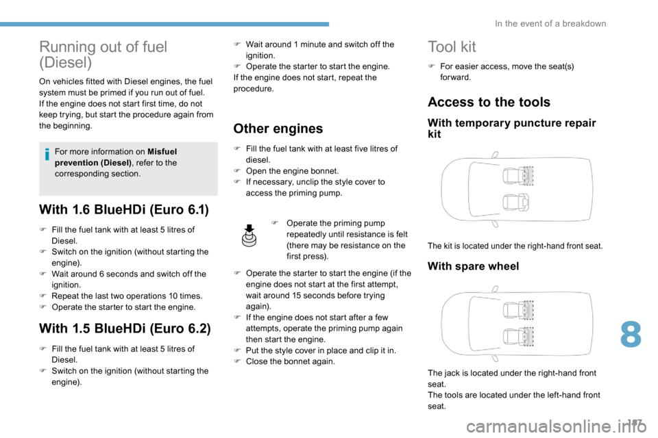
Access to the tools
With temporary puncture repair
kit
The kit is located under the right-hand front seat.
With spare wheel
The jack is located under the right-hand front
seat.
The tools are located under the left-hand front
seat.
8
In the event of a breakdown
Page 190 of 312

188
Details of the tool kit
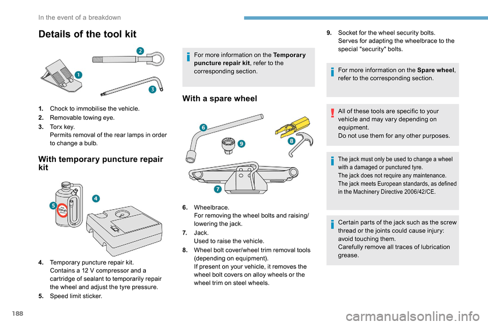
1.Chock to immobilise the vehicle.
2. Removable towing eye.
3. To r x k e y.
Permits removal of the rear lamps in order
to change a bulb.
With temporary puncture repair
kit
4.Temporary puncture repair kit.
Contains a 12
V compressor and a
cartridge of sealant to temporarily repair
the wheel and adjust the tyre pressure.
5. Speed limit sticker. For more information on the Temporary
puncture repair kit
, refer to the
corresponding section.
With a spare wheel
6. Wheelbrace.
For removing the wheel bolts and raising/
lowering the jack.
7. Jack.
Used to raise the vehicle.
8. Wheel bolt cover/wheel trim removal tools
(depending on equipment).
If present on your vehicle, it removes the
wheel bolt covers on alloy wheels or the
wheel trim on steel wheels. 9.
Socket for the wheel security bolts.
Ser ves for adapting the wheelbrace to the
special "security" bolts.
For more information on the Spare wheel ,
refer to the corresponding section.
All of these tools are specific to your
vehicle and may vary depending on
equipment.
Do not use them for any other purposes.
The jack must only be used to change a wheel
with a damaged or punctured tyre.
The jack does not require any maintenance.
The jack meets European standards, as defined
in the Machinery Directive 2006/42/CE.
Certain parts of the jack such as the screw
thread or the joints could cause injury:
avoid touching them.
Carefully remove all traces of lubrication
grease.
In the event of a breakdown
Page 191 of 312

189
The vehicle's electric system allows the
connection of the compressor for long
enough to inflate a tyre after a puncture
repair.
For more information on the Tool kit, refer
to the corresponding section.
Repair procedure
F Park the vehicle without obstructing any traffic and apply the parking brake.
F
F
ollow the safety instructions (hazard warning
lamps, warning triangle, wearing high visibility
vest, etc.) according to the legislation in force
in the country where you are driving.
F
S
witch off the ignition.
F Uncoil the pipe stowed under the compressor.
Avoid removing any foreign bodies which
have penetrated into the tyre.
It is designed to repair most punctures
which could affect the tyre, located on the
tyre tread or shoulder.
F
R
emove the valve cap from the tyre to be
repaired, and place it in a clean area.
F
C
onnect the pipe from the compressor to
the bottle of sealant. F
T
urn the sealant bottle over and secure it in
the notch provided on the compressor.
F
C
onnect the hose from the bottle of sealant
to the valve of the tyre to be repaired and
tighten firmly.
Temporary puncture
repair kit
Scan the QR code on page 3 to view
explanatory videos.
Comprising a compressor and a sealant
cartridge, it allows the temporary repair of
a tyre so that you can drive to the nearest
garage.
F
C
heck that the compressor switch is at the
" O " position.
8
In the event of a breakdown
Page 193 of 312

191
F Check that the compressor switch is at the "O " position.
F
U
ncoil fully the electric cable, stowed under
the compressor.
F
C
onnect the compressor's electric plug to
the vehicle's 12
V socket.
F
S
witch on the ignition. Only the 12
V socket located at the front
of the vehicle can be used to power the
compressor. If a pressure of 2 bars is not reached after
7
m
inutes, this indicates that the tyre is not
repairable; contact a PEUGEOT dealer or
a qualified workshop for assistance.
F
O
nce the correct pressure is reached, put
the switch to the " O" position.
F
R
emove the kit then stow it.
Do not drive more than 125 miles (200 km)
with the repaired tyre; see a PEUGEOT
dealer or a qualified workshop to change
the tyre.
Should the pressure of one or more tyres
be adjusted, it is necessary to reinitialise
the under-inflation detection system.
For more information on Tyre under-
inflation detection , refer to the
corresponding section.
F
S
crew the pipe onto the valve and tighten
f i r m l y. F
S
tart the compressor by placing the switch
at position " I" and adjust the pressure to the
value shown on the vehicle's tyre pressure
label. To deflate: press the black button
located on the compressor pipe, near the
valve connection. The tyre inflation pressures are given on
this label.
Spare wheel
Scan the QR code on page 3 to view
explanatory videos.
Procedure for changing a damaged wheel with
the spare wheel using the tools provided with
the vehicle.
Checking/adjusting tyre
pressures
You can also use the compressor,
without injecting sealant, to check and, if
necessary, adjust the tyre pressures.
F
R
emove the valve cap from the tyre and
place it in a clean area.
F
U
ncoil the pipe stowed under the
compressor.
8
In the event of a breakdown
Page 194 of 312

192
Access to the spare wheel
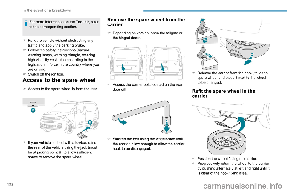
F Access to the spare wheel is from the rear.
F
I
f your vehicle is fitted with a towbar, raise
the rear of the vehicle using the jack (must
be at jacking point B ) to allow sufficient
space to remove the spare wheel.
Remove the spare wheel from the
carrier
F Depending on version, open the tailgate or the hinged doors.
F
A
ccess the carrier bolt, located on the rear
door sill.
F
S
lacken the bolt using the wheelbrace until
the carrier is low enough to allow the carrier
hook to be disengaged. F
R
elease the carrier from the hook, take the
spare wheel and place it next to the wheel
to be changed.
Refit the spare wheel in the
carrier
F Position the wheel facing the carrier.
F P rogressively return the wheel to the carrier
by pushing alternately at left and right until it
is clear of the hook fixing area.
For more information on the Tool kit
, refer
to the corresponding section.
F
P
ark the vehicle without obstructing any
traffic and apply the parking brake.
F
F
ollow the safety instructions (hazard
warning lamps, warning triangle, wearing
high visibility vest, etc.) according to the
legislation in force in the country where you
are driving.
F
S
witch off the ignition.
In the event of a breakdown
Page 197 of 312

195
After changing a wheel
Stow the punctured wheel in the carrier.
Go to a PEUGEOT dealer or a qualified
workshop as soon as possible.
Have the punctured tyre examined. After
inspection, the technician will advise you
on whether the tyre can be repaired or if it
must be replaced.
Some driving aid functions should be
disabled, e.g. the Active Safety Brake.If your vehicle has tyre under-inflation
detection, check the tyre pressures and
reinitialise the system.
For more information on Under-inflation
detection
, refer to the corresponding
section.
Wheel with wheel trim
When refitting the wheel , refit the wheel
trim starting by placing its notch facing the
valve and press around its edge with the
palm of your hand.
Changing a bulb
The headlamps have polycarbonate
lenses with a protective coating:
F
d
o not clean them using a dr y or
abrasive cloth, nor with a detergent
or solvent product,
F
u
se a sponge and soapy water or a pH
neutral product,
F
w
hen using a high pressure washer
on persistent marks, do not keep the
lance directed towards the lamps or
their edges for too long, so as not to
damage their protective coating and
seals.
Changing a bulb should only be done after
the headlamp has been switched off for
several minutes (risk of serious burns).
F
D
o not touch the bulb directly with your
fingers, use a lint-free cloth.
It is essential only to use anti-ultraviolet
(UV) type bulbs, so as not to damage the
headlamp.
Always replace a failed bulb with a new
bulb with the same type and specification.
Fitting a steel or "
space-saver" spare
wheel
If your vehicle is fitted with alloy wheels,
when tightening the bolts on fitting it is
normal to notice that the washers do not
come into contact with the steel or "space-
saver" spare wheel. The wheel is secured
by the conical contact of each bolt.
The tyre inflation pressures are given on
this label.
8
In the event of a breakdown
Page 199 of 312

197
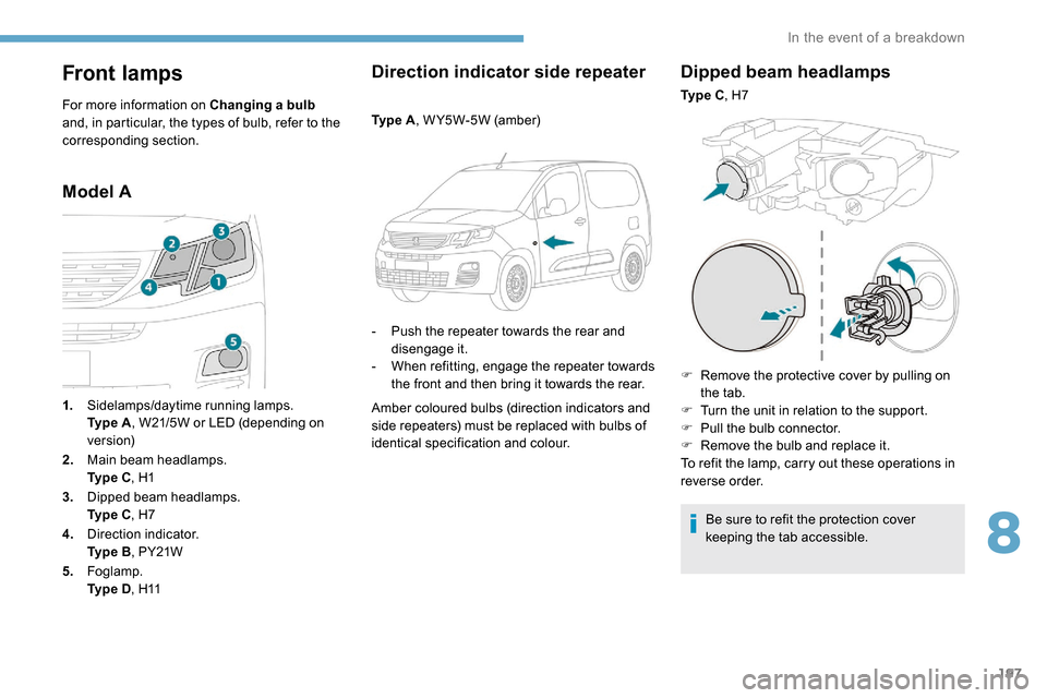
Front lamps
For more information on Changing a bulb
and, in particular, the types of bulb, refer to the
corresponding section.
Model A Direction indicator side repeater
Ty p e A
, W Y5W-5W (amber)
-
P
ush the repeater towards the rear and
disengage it.
-
W
hen refitting, engage the repeater towards
the front and then bring it towards the rear.
Amber coloured bulbs (direction indicators and
side repeaters) must be replaced with bulbs of
identical specification and colour.
Dipped beam headlamps
Ty p e C , H7
F
R
emove the protective cover by pulling on
the tab.
F
T
urn the unit in relation to the support.
F
P
ull the bulb connector.
F
R
emove the bulb and replace it.
To refit the lamp, carry out these operations in
reverse order.
Be sure to refit the protection cover
keeping the tab accessible.
1.
Sidelamps/daytime running lamps.
Ty p e
A , W21/5W or LED (depending on
ve r s i o n)
2. Main beam headlamps.
Ty p e
C , H1
3. Dipped beam headlamps.
Ty p e
C , H7
4. Direction indicator.
Ty p e
B , PY21W
5. Foglamp.
Ty p e
D , H11
8
In the event of a breakdown