2019 Peugeot Partner side lamps
[x] Cancel search: side lampsPage 158 of 312

156
During a correction, if the driver is inactive
(not holding the steering wheel for
10 seconds), a warning message appears.
If the driver remains inactive (not holding
the steering wheel for 2
more seconds),
the correction is interrupted.
Risk of undesirable operation
The system is not intended for driving in the
following situations:
-
d
riving on a racing circuit,
-
d
riving with a trailer,
-
d
riving on a rolling stand,
-
d
riving on unstable sur faces.
Malfunction
Operating limits
The system goes into standby automatically in
the following cases:
-
t
he ASR /DSC systems are deactivated or
the ESC operation is triggered,
-
s
peed below 40 mph (65 km/h) or greater
than 112
mph (180 km/h),
-
c
onnected electrically to a trailer,
-
u
se of the "space-saver" spare
wheel detected (as detection is not
immediate, deactivation of the system is
recommended),
-
d
ynamic driving style detected, pressure on
the brake or accelerator pedal,
-
d
riving where there are no lane markings,
-
a
ctivation of the direction indicators,
-
c
rossing the inside line on a bend,
-
d
riving in a tight corner,
-
i
nactivity by the driver detected during
correction.
Deactivation of the system is recommended in
the following situations:
-
d
riving on a road sur face in poor condition,
-
u
nfavourable climatic conditions,
-
d
riving on slippery sur faces (ice).In the event of a fault with the system, you are
alerted by the illumination of these warning
lamps in the instrument panel, accompanied by
the display of a message and an audible signal.
Have the system checked by a PEUGEOT
dealer or a qualified workshop.
The following situations may interfere with
the operation of the system or prevent it
from working:
-
c
onditions of poor visibility (inadequate
street lighting, snowfall, rain, fog),
-
d
azzle (headlamps of an oncoming
vehicle, low sun, reflections on a damp
road, leaving a tunnel, alternating
shade and light),
-
w
indscreen area located in front of the
camera: dirty, misted, frost-covered,
snow-covered, damaged or covered by
a s t i c ke r,
-
l
ane markings worn, hidden (snow,
mud) or multiple (roadworks, etc.),
-
r
unning close to the vehicle in front
(the lane markings may not be
detected),
-
r
oads that are narrow, winding, etc.
Driving
Page 159 of 312

157
A warning lamp appears in the door mirror on
the side in question:
-
f
ixed , immediately, when being overtaken,
-
f
lashing , after a delay of about one second,
when overtaking a vehicle slowly, and when
the direction indicator is used. This system is designed to improve safety
when driving and is in no circumstances
a substitute for the use of the interior rear
view mirror and door mirrors. It is the
driver's responsibility to constantly check
the traffic, to assess the distances and
relative speeds of other vehicles and to
predict their movements before deciding
whether to change lane.
The alert is given by a warning lamp which
comes on in the door mirror on the side in
question as soon as a vehicle – car, lorry,
bicycle – is detected and the following
conditions are fulfilled:
-
a
ll the vehicles must be moving in the same
direction and in adjacent lanes,
-
t
he speed of the vehicle must be between 7
and 87 mph (12 and 140 km/h),
-
y
ou overtake a vehicle with a speed
difference of less than 6 mph (10 km/h),
-
a v
ehicle overtakes you with a speed
difference of less than 15 mph (25 km/h),
-
t
he traffic must be flowing normally,
-
i
n the case of an overtaking manoeuvre,
if this is prolonged and the vehicle being
overtaken returns to the blind spot,
-
y
ou are driving on a straight or slightly
curved road,
-
y
our vehicle is not towing a trailer, a
caravan, etc.
Blind Spot Detection
This driving assistance system warns the driver
of the presence of another vehicle in the blind
spot angle of his vehicle (areas masked from
the driver's field of vision), as soon as this
presents a potential danger. No alert will be given in the following situations:
-
i
n the presence of non-moving objects
(parked vehicles, barriers, street lamps,
road signs, etc.),
-
w
ith vehicles moving in the opposite
direction,
-
d
riving on a winding road or a sharp corner,
6
Driving
Page 165 of 312

163
Malfunction
If a fault occurs when shifting to
reverse, this warning lamp comes on
in the instrument panel, accompanied
by a message and an audible signal
(short beep).
Contact a PEUGEOT dealer or a qualified
workshop to have the system checked.
Reversing camera
With the ignition on, this system uses a camera
located near the third brake lamp to display a
view of the rear of your vehicle on the output
screen (if it is a panel van or has a solid
partition).
The reversing camera is activated automatically
when reverse gear is engaged. The image is
displayed on the output screen. The output
screen switches off when the gearbox is in
neutral or in a for ward gear. The blue lines 1 represent the general direction
of the vehicle (the gap corresponds to the width
of your vehicle with the mirrors).
The red line 2 represents a distance of about
30
cm beyond the edge of your vehicle's rear
b u m p e r.
The green lines 3 represent distances of
about 1 and 2
metres beyond the edge of your
vehicle's rear bumper.
The turquoise blue curves 4 represent the
maximum turning circle.
The reversing camera is a driving aid which
cannot, in any circumstances, replace the
need for vigilance on the part of the driver.
Some objects may not be seen by the
camera. Certain vehicles may be difficult to see
(dark colours, headlamps off) when the
brightness of the screen is reduced by the
vehicle’s lighting dimmer.
The image quality may be affected by the
environment, the exterior conditions (rain,
dirt, dust), the driving mode, the lighting
conditions (night, low sun).
In the presence of areas in shade, or in
conditions of bright sunlight or inadequate
lighting, the image may be darkened and
with lower contrast.
Obstacles may appear further away than
they actually are in reality.
During parking manoeuvres and lane
changes, it is important to check the sides
of the vehicle using the mirrors.
The rear parking sensors also provide
information on the vehicle's surroundings.
6
Driving
Page 167 of 312

165
The blue dimension lines 1 represent the width
of your vehicle with the mirrors unfolded.
The red line 2 represents a distance of 30 cm
from the rear bumper; the two green lines 3 and
4 represent 1
m and 2 m, respectively.
The blue cur ves 5 appear successively; they
are based on the position of the steering wheel
and represent the turning circle radius of your
vehicle.
The orange dashes 6 represent the opening
radii of the rear doors. - The
visual reversing aid : allows a view of
the area close to the rear of the vehicle. Some items may not be seen by the rear
camera.
Certain vehicles may be difficult to see
(dark colours, headlamps off) when the
brightness of the screen is reduced by the
vehicle’s lighting dimmer.
The image quality may be affected by the
environment, the exterior conditions (rain,
dirt, dust), the driving mode, the lighting
conditions (night, low sun).
In the presence of areas in shade, or in
conditions of bright sunlight or inadequate
lighting, the image may be darkened and
with lower contrast.Obstacles may appear further away than
they actually are in reality.
During parking manoeuvres and lane
changes, it is important to check the sides
of the vehicle using the mirrors.
The rear parking sensors also provide
information on the vehicle's surroundings.
Activation/Deactivation
The system starts when the ignition is switched
on.
This system is a driving aid which cannot,
in any circumstances, replace the need for
vigilance on the part of the driver.
Please routinely check your exterior
mirrors while driving and during
manoeuvres.
F
W
ith the ignition on, press the
corresponding button below the screen to
switch the output screen on/off.
A message appears.
6
Driving
Page 199 of 312

197
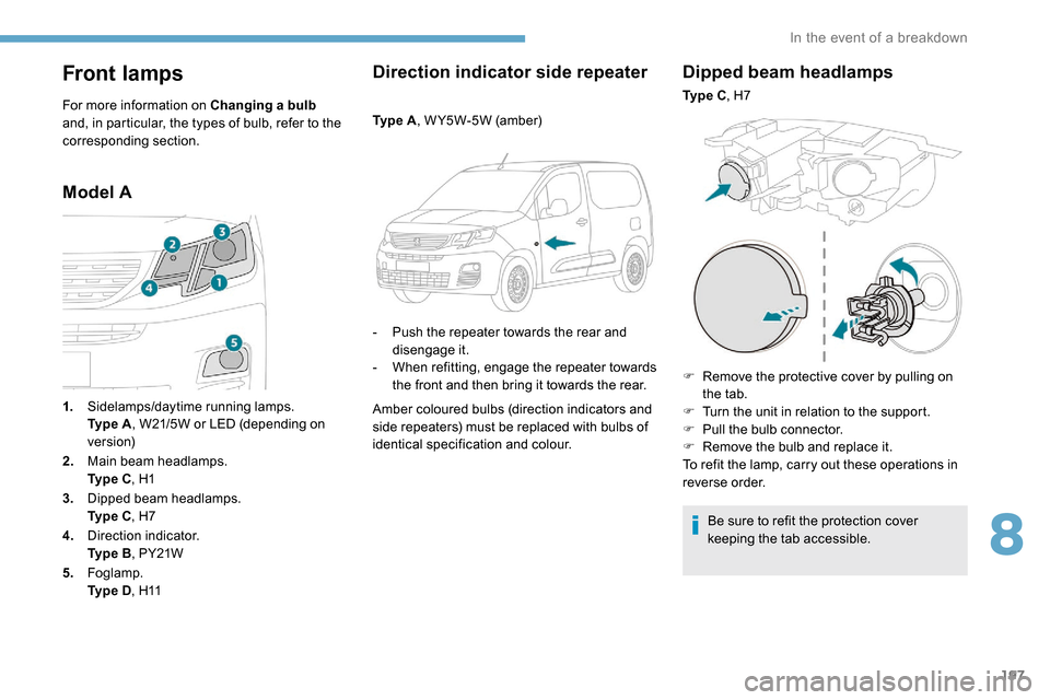
Front lamps
For more information on Changing a bulb
and, in particular, the types of bulb, refer to the
corresponding section.
Model A Direction indicator side repeater
Ty p e A
, W Y5W-5W (amber)
-
P
ush the repeater towards the rear and
disengage it.
-
W
hen refitting, engage the repeater towards
the front and then bring it towards the rear.
Amber coloured bulbs (direction indicators and
side repeaters) must be replaced with bulbs of
identical specification and colour.
Dipped beam headlamps
Ty p e C , H7
F
R
emove the protective cover by pulling on
the tab.
F
T
urn the unit in relation to the support.
F
P
ull the bulb connector.
F
R
emove the bulb and replace it.
To refit the lamp, carry out these operations in
reverse order.
Be sure to refit the protection cover
keeping the tab accessible.
1.
Sidelamps/daytime running lamps.
Ty p e
A , W21/5W or LED (depending on
ve r s i o n)
2. Main beam headlamps.
Ty p e
C , H1
3. Dipped beam headlamps.
Ty p e
C , H7
4. Direction indicator.
Ty p e
B , PY21W
5. Foglamp.
Ty p e
D , H11
8
In the event of a breakdown
Page 200 of 312

198
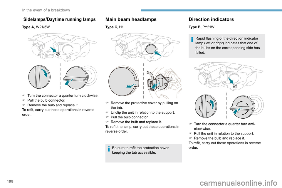
Sidelamps/Daytime running lamps
Ty p e A, W21/5W
F
T
urn the connector a quarter turn clockwise.
F
P
ull the bulb connector.
F
R
emove the bulb and replace it.
To refit, carry out these operations in reverse
o r d e r.
Main beam headlamps
Ty p e C , H1
F
R
emove the protective cover by pulling on
the tab.
F
U
nclip the unit in relation to the support.
F
P
ull the bulb connector.
F
R
emove the bulb and replace it.
To refit the lamp, carry out these operations in
reverse order.
Be sure to refit the protection cover
keeping the tab accessible.
Direction indicators
Ty p e B, PY21W
Rapid flashing of the direction indicator
lamp (left or right) indicates that one of
the bulbs on the corresponding side has
failed.
F
T
urn the connector a quarter turn anti-
clockwise.
F
P
ull the unit in relation to the support.
F
R
emove the bulb and replace it.
To refit, carry out these operations in reverse
o r d e r.
In the event of a breakdown
Page 201 of 312

199
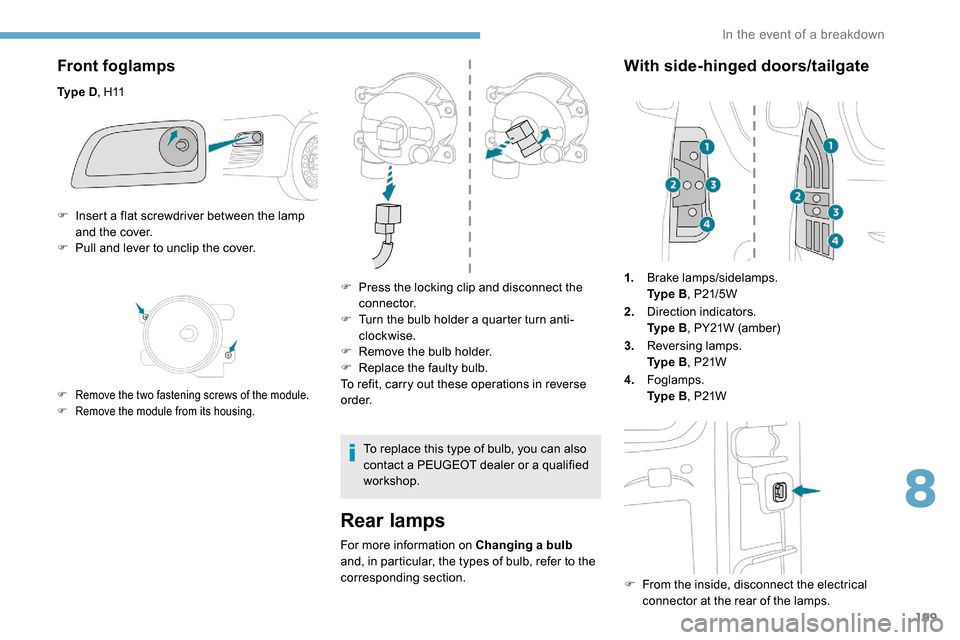
Front foglamps
Ty p e D, H11
Rear lamps
For more information on Changing a bulb
and, in particular, the types of bulb, refer to the
corresponding section.
With side-hinged doors/tailgate
1. Brake lamps/sidelamps.
Ty p e
B, P21/5W
2. Direction indicators.
Ty p e
B, PY21W (amber)
3. Reversing lamps.
Ty p e
B, P21W
4. Foglamps.
Ty p e
B, P21W
F
F
rom the inside, disconnect the electrical
connector at the rear of the lamps.
F
I
nsert a flat screwdriver between the lamp
and the cover.
F
P
ull and lever to unclip the cover.
F Remove the two fastening screws of the module.
F
R emove the module from its housing.
F Press the locking clip and disconnect the connector.
F
T
urn the bulb holder a quarter turn anti-
clockwise.
F
R
emove the bulb holder.
F
R
eplace the faulty bulb.
To refit, carry out these operations in reverse
o r d e r.
To replace this type of bulb, you can also
contact a PEUGEOT dealer or a qualified
workshop.
8
In the event of a breakdown
Page 202 of 312

200
Take care to reposition the tabs and the supply
wire correctly to avoid trapping the wire.
After changing a rear direction
indicator bulb, the reinitialisation time is
approximately 2
minutes or more.
Number plate lamps
Ty p e A, W5W -5W
F
R
emove the two fixing bolts using the Torx
key provided in your vehicle.
For more information on the Tool kit , refer
to the corresponding section.
F
F
rom the outside, pull the whole lamp unit
towards you (with side-hinged doors )
or towards the centre of the vehicle (with
tailgate ).
F
M
ove aside the tabs, then extract the bulb
h o l d e r.
F
R
emove the faulty bulb by pressing lightly
on it, then turning it a quarter turn anti-
clockwise. F
C
hange the bulb.
To refit, carry out these operations in reverse
o r d e r.
With side-hinged doors
F Unclip the interior trim.
F D isconnect the connector by moving aside
its tab.
F
T
urn the bulb holder a quarter turn anti-
clockwise.
F
C
hange the bulb.
F
P
ut the bulb holder back in place and
reconnect the connector.
F
P
ut the trim back in place.
With tailgate
F Remove the plastic lens using a screwdriver.
F
C
hange the bulb.
F
R
efit the plastic lens and press on it.
Third brake lamp
Ty p e A , W16W -16W
F
U
nscrew the two nuts.
F
P
ush the pins.
F
I
f necessary, disconnect the connector to
remove the lamp.
F
C
hange the bulb.
In the event of a breakdown