2019 Peugeot Partner ECU
[x] Cancel search: ECUPage 113 of 312
111
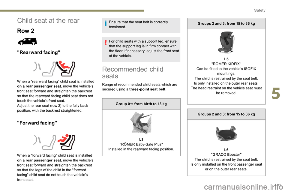
Child seat at the rear
Row 2
"Rearward facing"
"Forward facing"
Ensure that the seat belt is correctly
tensioned.
For child seats with a support leg, ensure
that the support leg is in firm contact with
the floor. If necessary, adjust the front seat
of the vehicle.
When a "rear ward facing" child seat is installed
on a rear passenger seat , move the vehicle's
front seat for ward and straighten the backrest
so that the rear ward facing child seat does not
touch the vehicle's front seat.
Adjust the rear seat (row 2) to the fully back
position, with the backrest straightened.
When a "for ward facing" child seat is installed
on a rear passenger seat , move the vehicle's
front seat for ward and straighten the backrest
so that the legs of the child in the "for ward
facing" child seat do not touch the vehicle's
front seat.
Recommended child
seats
Range of recommended child seats which are
secured using a three-point seat belt .
Group 0+: from bir th to 13
kg
L1
"RÖMER Baby-Safe Plus"
Installed in the rearward facing position. Groups 2 and 3: from 15 to 36
kg
L5
"RÖMER KIDFIX"
Can be fitted to the vehicle's ISOFIX mountings.
The child is restrained by the seat belt.
Is only installed on the outer rear seats.
The head restraint on the vehicle seat must be removed.
Groups 2 and 3: from 15 to 36
kg
L6
"GRACO Booster"
The child is restrained by the seat belt.
Is only installed on the front passenger seat or on the outer rear seats.
5
Safety
Page 114 of 312
112
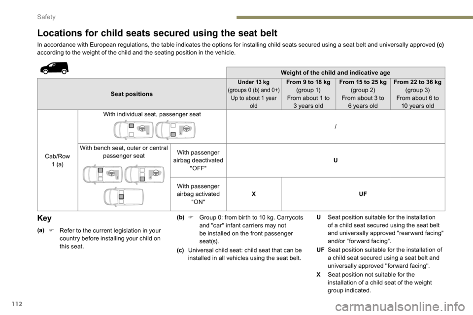
Locations for child seats secured using the seat belt
In accordance with European regulations, the table indicates the options for installing child seats secured using a seat belt and universally approved (c)
according to the weight of the child and the seating position in the vehicle.
Weight of the child and indicative age
Seat positions
Under 13 kg
(
groups 0 (b) and 0+)
Up to about 1 year oldFrom 9 to 18 kg
( group 1)
From about 1 to 3
years old From 15 to 25
kg
(group 2)
From about 3 to 6
years oldFrom 22 to 36
kg
(group 3)
From about 6 to 10
years old
Cab/Row 1 (a) With individual seat, passenger seat
/
With bench seat, outer or central passenger seat With passenger
airbag deactivated "OFF" U
With passenger
airbag activated "ON" X
UF
Key
(a)
F R efer to the current legislation in your
country before installing your child on
this seat. (b)
F
G
roup 0: from birth to 10 kg. Carrycots
and "car" infant carriers may not
be installed on the front passenger
seat(s).
(c) Universal child seat: child seat that can be
installed in all vehicles using the seat belt. U
Seat position suitable for the installation
of a child seat secured using the seat belt
and universally approved "rearward facing"
and/or "forward facing".
UF Seat position suitable for the installation of
a child seat secured using a seat belt and
universally approved "forward facing".
X Seat position not suitable for the
installation of a child seat of the weight
group indicated.
Safety
Page 115 of 312
113
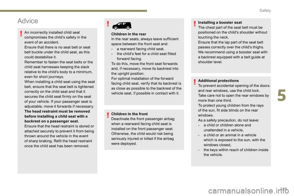
Advice
An incorrectly installed child seat
compromises the child's safety in the
event of an accident.
Ensure that there is no seat belt or seat
belt buckle under the child seat, as this
could destabilise it.
Remember to fasten the seat belts or the
child seat harnesses keeping the slack
relative to the child's body to a minimum,
even for short journeys.
When installing a child seat using the seat
belt, ensure that the seat belt is tightened
correctly on the child seat and that it
secures the child seat firmly on the seat
of your vehicle. If your passenger seat is
adjustable, move it forwards if necessary.
The head restraint must be removed
before installing a child seat with a
backrest on a passenger seat.
Ensure that the head restraint is stored or
attached securely to prevent it from being
thrown around the vehicle in the event
of sharp braking. Refit the head restraint
once the child seat has been removed.Children in the front
Deactivate the front passenger airbag
when a rear ward facing child seat is
installed on the front passenger seat.
Otherwise, the child would risk being
seriously injured or killed if the airbag
were deployed.Installing a booster seat
The chest part of the seat belt must be
positioned on the child's shoulder without
touching the neck.
Ensure that the lap part of the seat belt
passes correctly over the child's thighs.
We recommend using a booster seat with
a backrest equipped with a belt guide at
shoulder level.
Additional protections
To prevent accidental opening of the doors
and rear windows, use the child lock.
Take care not to open the rear windows by
more than one third.
To protect young children from the rays
of the sun, fit side blinds on the rear
windows.
As a safety precaution, do not leave:
-
a c
hild or children alone and
unattended in a vehicle,
-
a c
hild or an animal in a vehicle
which is exposed to the sun, with the
windows closed,
-
t
he keys within reach of children inside
the vehicle.
Children in the rear
In the rear seats, always leave sufficient
space between the front seat and:
-
a r
ear ward facing child seat,
-
t
he child's feet for a child seat fitted
forward facing.
To do this, move the front seat for wards
and, if necessary, move its backrest into
the upright position.
For optimal installation of the forward
facing child seat, verify that its backrest is
as close as possible to the backrest of the
vehicle seat, if possible in contact with it.
5
Safety
Page 151 of 312

149
The system is not intended for the
following situations:
-
i
f the front end of the vehicle has
been modified (addition of long-range
headlamps, painting of the front
bumper),
-
d
riving on a racing circuit,
-
r
unning on a rolling road,
-
u
se of snow chains, non-slip covers or
studded tyres.
The use of mats not approved by
PEUGEOT may inter fere with the
operation of the cruise control.
To avoid any risk of jamming the pedals:
-
e
nsure that the mat is secured
c o r r e c t l y,
-
d
o not place one mat on top of another.
The following situations may interfere with
the operation of the system or prevent it
from working:
-
d
riving on a winding road,
-
p
oor visibility (inadequate street
lighting, falling snow, heavy rain, dense
fog, etc.),
-
d
azzle (headlamps of an oncoming
vehicle, low sun, reflections on a damp
road, leaving a tunnel, alternating
shade and light, etc.),
-
c
amera obstructed (mud, frost, snow,
condensation, etc.).
In these situations, detection performance
may be reduced.Malfunction
If the cruise control
malfunctions, dashes are
displayed instead of the
cruise control speed setting.
If this warning lamp comes
on, accompanied by an alert
message and an audible
signal, this confirms a
malfunction.
The adaptive cruise control deactivates
automatically if the use of a "space-saver"
type spare wheel is detected or if there is
a malfunction on the lateral brake lamps or
trailer brake lamps (for approved trailers).
The cruise control operates by day and
night, in fog or moderate rainfall.
However, it is strongly recommended that
you always keep a safe distance from
vehicles ahead, according to the driving
conditions, the weather and the road
sur face.
Use the cruise control only where the
driving conditions allow running at a
constant speed and keeping an adequate
safety distance.
Do not activate the cruise control in urban
areas where pedestrians are likely to
cross the road, in heavy traffic (except for
versions with EAT8 gearbox), on winding
or steep roads, on slippery or flooded
roads, when there is snowfall, if the
windscreen is damaged or when the brake
lamps have failed.
In certain circumstances, it may not
be possible for the speed setting to be
maintained or even attained: loaded
vehicle, ascending a steep hill, etc.
Have the system checked by a PEUGEOT
dealer or a qualified workshop.
Memorising speeds
Linked to the speed limiter and programmable
cruise control, this function allows speed limits
to be registered which will then be suggested
as settings for these two systems.
You can memorise several speed settings for
each system.
6
Driving
Page 179 of 312
177
Load reduction mode
System which manages the use of certain
functions according to the level of charge
remaining in the battery.
When the vehicle is being driven, the load
reduction function temporarily deactivates
certain functions, such as air conditioning,
heated rear screen, etc.
The deactivated functions are reactivated
automatically as soon as conditions permit.
Roof bars/Roof rack
Recommendations
Distribute the load uniformly, taking care
to avoid overloading one of the sides.
Arrange the heaviest part of the load as
close as possible to the roof.
Secure the load firmly.
Drive gently: the vehicle will be more
susceptible to the effects of side winds
and its stability may be affected.
Regularly check the security and tight
fastening of the roof bars and racks, at
least before each trip.As a safety measure and to avoid
damaging the roof, it is essential to use
the roof bars and racks approved for your
vehicle.
Obser ve the instructions on fitting and use
contained in the guide supplied with the
roof bars and racks. In the event of loading (
not exceeding
40 cm in height) on the roof, do not
exceed the following loads:
-
T
ransverse bars on longitudinal bars:
80 kg
.
-
T
wo transverse bars bolted to the roof:
100
kg
.
-
T
hree transverse bars bolted to the
roof: 15 0
kg
.
-
A
n aluminium rack: 120
kg
.
-
A s
teel rack: 115
k g
.
If the height exceeds 40 cm, adapt the
speed of the vehicle to the profile of the
road to avoid damaging the roof bars
or the roof rack and the fixings on the
vehicle.
Be sure to refer to national legislation in
order to comply with the regulations for
transporting objects which are longer than
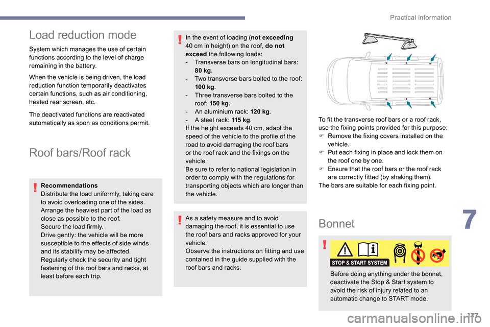
the vehicle. To fit the transverse roof bars or a roof rack,
use the fixing points provided for this purpose:
F
R
emove the fixing covers installed on the
vehicle.
F
P
ut each fixing in place and lock them on
the roof one by one.
F
E
nsure that the roof bars or the roof rack
are correctly fitted (by shaking them).
The bars are suitable for each fixing point.
Bonnet
Before doing anything under the bonnet,
deactivate the Stop & Start system to
avoid the risk of injury related to an
automatic change to START mode.
7
Practical information
Page 190 of 312
188
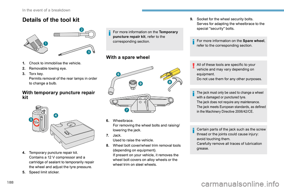
Details of the tool kit
1.Chock to immobilise the vehicle.
2. Removable towing eye.
3. To r x k e y.
Permits removal of the rear lamps in order
to change a bulb.
With temporary puncture repair
kit
4.Temporary puncture repair kit.
Contains a 12
V compressor and a
cartridge of sealant to temporarily repair
the wheel and adjust the tyre pressure.
5. Speed limit sticker. For more information on the Temporary
puncture repair kit
, refer to the
corresponding section.
With a spare wheel
6. Wheelbrace.
For removing the wheel bolts and raising/
lowering the jack.
7. Jack.
Used to raise the vehicle.
8. Wheel bolt cover/wheel trim removal tools
(depending on equipment).
If present on your vehicle, it removes the
wheel bolt covers on alloy wheels or the
wheel trim on steel wheels. 9.
Socket for the wheel security bolts.
Ser ves for adapting the wheelbrace to the
special "security" bolts.
For more information on the Spare wheel ,
refer to the corresponding section.
All of these tools are specific to your
vehicle and may vary depending on
equipment.
Do not use them for any other purposes.
The jack must only be used to change a wheel
with a damaged or punctured tyre.
The jack does not require any maintenance.
The jack meets European standards, as defined
in the Machinery Directive 2006/42/CE.
Certain parts of the jack such as the screw
thread or the joints could cause injury:
avoid touching them.
Carefully remove all traces of lubrication
grease.
In the event of a breakdown
Page 191 of 312

189
The vehicle's electric system allows the
connection of the compressor for long
enough to inflate a tyre after a puncture
repair.
For more information on the Tool kit, refer
to the corresponding section.
Repair procedure
F Park the vehicle without obstructing any traffic and apply the parking brake.
F
F
ollow the safety instructions (hazard warning
lamps, warning triangle, wearing high visibility
vest, etc.) according to the legislation in force
in the country where you are driving.
F
S
witch off the ignition.
F Uncoil the pipe stowed under the compressor.
Avoid removing any foreign bodies which
have penetrated into the tyre.
It is designed to repair most punctures
which could affect the tyre, located on the
tyre tread or shoulder.
F
R
emove the valve cap from the tyre to be
repaired, and place it in a clean area.
F
C
onnect the pipe from the compressor to
the bottle of sealant. F
T
urn the sealant bottle over and secure it in
the notch provided on the compressor.
F
C
onnect the hose from the bottle of sealant
to the valve of the tyre to be repaired and
tighten firmly.
Temporary puncture
repair kit
Scan the QR code on page 3 to view
explanatory videos.
Comprising a compressor and a sealant
cartridge, it allows the temporary repair of
a tyre so that you can drive to the nearest
garage.
F
C
heck that the compressor switch is at the
" O " position.
8
In the event of a breakdown
Page 192 of 312
190
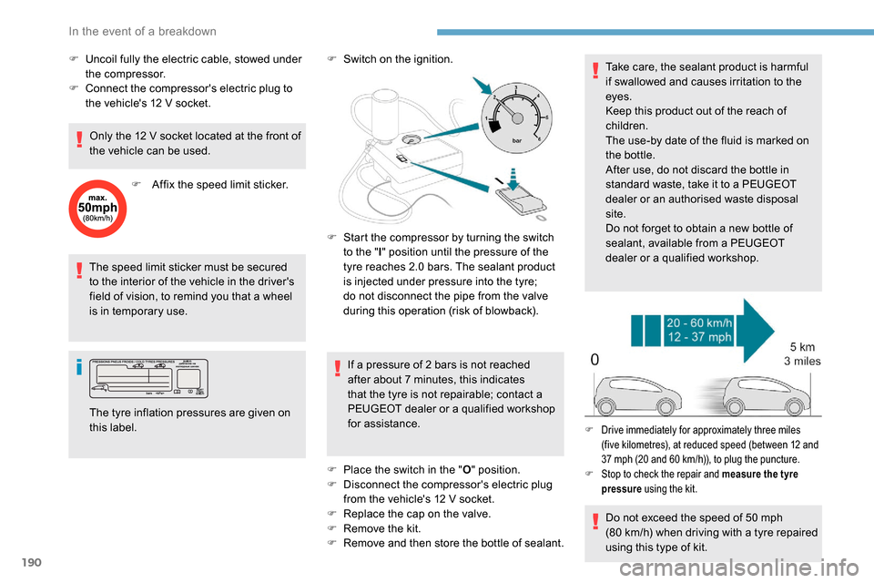
The speed limit sticker must be secured
to the interior of the vehicle in the driver's
field of vision, to remind you that a wheel
is in temporary use.F
S
witch on the ignition.
If a pressure of 2 bars is not reached
after about 7
minutes, this indicates
that the tyre is not repairable; contact a
PEUGEOT dealer or a qualified workshop
for assistance.
F
P
lace the switch in the "O" position.
F
D
isconnect the compressor's electric plug
from the vehicle's 12
V socket.
F
R
eplace the cap on the valve.
F
R
emove the kit.
F
R
emove and then store the bottle of sealant.Take care, the sealant product is harmful
if swallowed and causes irritation to the
eyes.
Keep this product out of the reach of
children.
The use-by date of the fluid is marked on
the bottle.
After use, do not discard the bottle in
standard waste, take it to a PEUGEOT
dealer or an authorised waste disposal
site.
Do not forget to obtain a new bottle of
sealant, available from a PEUGEOT
dealer or a qualified workshop.
The tyre inflation pressures are given on
this label. F
S
tart the compressor by turning the switch
to the " l" position until the pressure of the
tyre reaches 2.0 bars. The sealant product
is injected under pressure into the tyre;
do not disconnect the pipe from the valve
during this operation (risk of blowback).
Do not exceed the speed of 50
mph
(80
km/h) when driving with a tyre repaired
using this type of kit.
F Drive immediately for approximately three miles (five kilometres), at reduced speed (between 12 and
37
mph (20 and 60 km/h)), to plug the puncture.
F
S
top to check the repair and measure the tyre
pressure using the kit.
F Uncoil fully the electric cable, stowed under
the compressor.
F
C
onnect the compressor's electric plug to
the vehicle's 12
V socket.
Only the 12
V socket located at the front of
the vehicle can be used.
F
A
ffix the speed limit sticker.
In the event of a breakdown