2019 Peugeot Partner bulb
[x] Cancel search: bulbPage 5 of 312

3
bit.ly/helpPSA
.
.
Driving recommendations 115
Starting/switching off the engine 1 16
Anti-theft protection
1
20
Manual parking brake
1
21
Automatic electronic parking brake
1
21
Hill start assist
1
24
5-speed manual gearbox
1
25
6-speed manual gearbox
1
26
Automatic gearbox
1
26
Gear efficiency indicator
1
30
Stop & Start
1
30
Speed Limit recognition and
recommendation
133
Speed limiter
1
37
Programmable cruise control
1
39
Dynamic cruise control
1
42
Memorising speeds
1
49
Active Safety Brake with Distance Alert
and Intelligent emergency braking
assistance
150
Active Lane Departure Warning System
1
53
Blind Spot Detection
1
57
Fatigue detection system
1
59
Parking sensors
1
60
Reversing camera
1
63
Surround Rear Vision
1
64
Under-inflation detection
1
67Compatibility of fuels 1
70
Fuel tank 1 71
Diesel misfuel prevention
1
72
Snow chains
1
73
Towing device
1
73
Overload indicator
1
75
Energy economy mode
1
76
Roof bars/Roof rack
1
77
B o n n et
17 7
Engines
1
78
Checking levels
1
79
Checks
181
AdBlue
® (BlueHDi) 1 83
Advice on care 1 86
Running out of fuel (Diesel)
1
87
Tool kit
1
87
Temporary puncture repair kit
1
89
Spare wheel
1
91
Changing a bulb
1
95
Changing a fuse
2
01
12
V battery
2
03
To w i n g
2 0 6Dimensions
208
Engine technical data and towed loads
2
10
Identification markings
2
17
Driving
Practical information
In the event of a breakdown Technical data
Access to additional videos
Alphabetical index
Audio equipment and telematics
Bluetooth audio system
PEUGEOT Connect Radio
PEUGEOT Connect Nav
.
Contents
Page 6 of 312

4
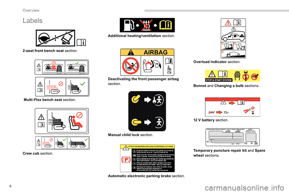
Labels
2-seat front bench seat section.
Multi-Flex bench seat section.
Crew cab section. Additional heating/ventilation
section.
Deactivating the front passenger airbag
section.
Manual child lock section.
Automatic electronic parking brake section.Overload indicator
section.
Bonnet and Changing a bulb sections.
12
V batter y section.
Temporary puncture repair kit and Spare
wheel sections.
Over view
Page 97 of 312

95
General safety
recommendations
Labels are affixed in different locations on
your vehicle. They include safety warnings
and vehicle identification information. Do
not remove them: they are an integral part
of your vehicle.
For any work on your vehicle, use a
qualified workshop that has the technical
information, skills and equipment required,
all of which a PEUGEOT dealer is able to
provide.
Depending on country regulations, some
safety equipment may be compulsory:
high visibility safety vests, warning
triangles, breathalysers, spare bulbs,
spare fuses, fire extinguisher, first aid kit,
mud flaps at the rear of the vehicle, etc.We draw your attention to the following
points:
-
T
he fitting of electrical equipment
or accessories not approved by
PEUGEOT may cause excessive
current consumption and faults and
failures with the electrical system of
your vehicle. Contact a PEUGEOT
dealer for information on the range of
recommended accessories.
-
A
s a safety measure, access to
the diagnostic socket, used for the
vehicle's electronic systems, is
reser ved strictly for PEUGEOT dealers
or qualified workshops, equipped
with the special tools required (risk
of malfunctions of the vehicle's
electronic systems that could cause
breakdowns or serious accidents).
The manufacturer cannot be held
responsible if this advice is not
followed.
-
A
ny modification or adaptation not
intended or authorised by PEUGEOT
or carried out without meeting the
technical requirements defined by
the manufacturer will result in the
suspension of the legal and contractual
warranties. Installation of accessory radio
communication transmitters
Before installing a radio communication
transmitter, you must contact a PEUGEOT
dealer for the specifications of compatible
transmitters (frequency, maximum power,
aerial position, specific installation
requirements), in line with the Vehicle
Electromagnetic Compatibility Directive
(2004/104/EC).
5
Safety
Page 190 of 312

188
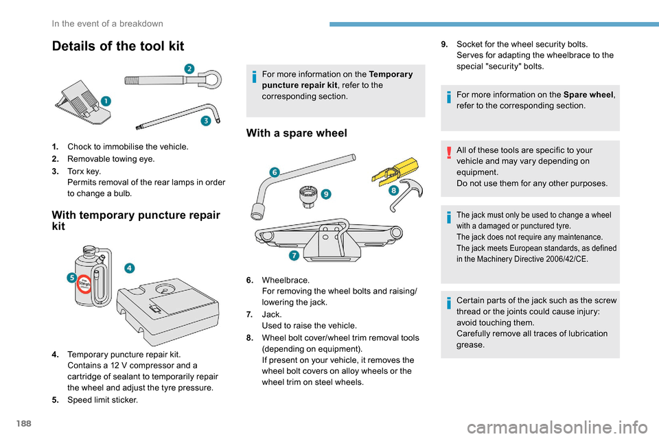
Details of the tool kit
1.Chock to immobilise the vehicle.
2. Removable towing eye.
3. To r x k e y.
Permits removal of the rear lamps in order
to change a bulb.
With temporary puncture repair
kit
4.Temporary puncture repair kit.
Contains a 12
V compressor and a
cartridge of sealant to temporarily repair
the wheel and adjust the tyre pressure.
5. Speed limit sticker. For more information on the Temporary
puncture repair kit
, refer to the
corresponding section.
With a spare wheel
6. Wheelbrace.
For removing the wheel bolts and raising/
lowering the jack.
7. Jack.
Used to raise the vehicle.
8. Wheel bolt cover/wheel trim removal tools
(depending on equipment).
If present on your vehicle, it removes the
wheel bolt covers on alloy wheels or the
wheel trim on steel wheels. 9.
Socket for the wheel security bolts.
Ser ves for adapting the wheelbrace to the
special "security" bolts.
For more information on the Spare wheel ,
refer to the corresponding section.
All of these tools are specific to your
vehicle and may vary depending on
equipment.
Do not use them for any other purposes.
The jack must only be used to change a wheel
with a damaged or punctured tyre.
The jack does not require any maintenance.
The jack meets European standards, as defined
in the Machinery Directive 2006/42/CE.
Certain parts of the jack such as the screw
thread or the joints could cause injury:
avoid touching them.
Carefully remove all traces of lubrication
grease.
In the event of a breakdown
Page 197 of 312

195
After changing a wheel
Stow the punctured wheel in the carrier.
Go to a PEUGEOT dealer or a qualified
workshop as soon as possible.
Have the punctured tyre examined. After
inspection, the technician will advise you
on whether the tyre can be repaired or if it
must be replaced.
Some driving aid functions should be
disabled, e.g. the Active Safety Brake.If your vehicle has tyre under-inflation
detection, check the tyre pressures and
reinitialise the system.
For more information on Under-inflation
detection
, refer to the corresponding
section.
Wheel with wheel trim
When refitting the wheel , refit the wheel
trim starting by placing its notch facing the
valve and press around its edge with the
palm of your hand.
Changing a bulb
The headlamps have polycarbonate
lenses with a protective coating:
F
d
o not clean them using a dr y or
abrasive cloth, nor with a detergent
or solvent product,
F
u
se a sponge and soapy water or a pH
neutral product,
F
w
hen using a high pressure washer
on persistent marks, do not keep the
lance directed towards the lamps or
their edges for too long, so as not to
damage their protective coating and
seals.
Changing a bulb should only be done after
the headlamp has been switched off for
several minutes (risk of serious burns).
F
D
o not touch the bulb directly with your
fingers, use a lint-free cloth.
It is essential only to use anti-ultraviolet
(UV) type bulbs, so as not to damage the
headlamp.
Always replace a failed bulb with a new
bulb with the same type and specification.
Fitting a steel or "
space-saver" spare
wheel
If your vehicle is fitted with alloy wheels,
when tightening the bolts on fitting it is
normal to notice that the washers do not
come into contact with the steel or "space-
saver" spare wheel. The wheel is secured
by the conical contact of each bolt.
The tyre inflation pressures are given on
this label.
8
In the event of a breakdown
Page 198 of 312

196
Halogen bulbs
To ensure good quality lighting, check
that the bulb is correctly positioned in its
housing.
After changing a bulb
When refitting, close the protective cover
very carefully to guarantee the sealing of
the lamp.
In some weather conditions (e.g. low
temperature or humidity), the presence
of misting on the internal sur face of the
glass of the headlamps and rear lamps is
normal; it disappears after the lamps have
been on for a few minutes. Opening the bonnet /Access to bulbs
With the engine warm, proceed with
caution – risk of burns!
Take care with objects or clothing that
could be caught in the blades of the
cooling fan – risk of strangulation!Types of bulb
Various types of bulb are fitted to your vehicle.
To remove them:
Ty p e A
Ty p e B
Ty p e C Ty p e D
All glass bulb: pull gently as it is fitted by
pressure.
Bayonet bulb: press on the bulb then turn it
anti-clockwise.
Halogen bulb: release the retaining spring from
its housing. Halogen bulb: turn the bulb anti-clockwise.
Halogen bulbs must be changed with
headlamp off and cold (risk of severe
burns). Do not touch the bulb directly, use
a lint-free cloth.
When each operation has been completed,
check the operation of the lighting.
In the event of a breakdown
Page 199 of 312

197
Front lamps
For more information on Changing a bulb
and, in particular, the types of bulb, refer to the
corresponding section.
Model A Direction indicator side repeater
Ty p e A
, W Y5W-5W (amber)
-
P
ush the repeater towards the rear and
disengage it.
-
W
hen refitting, engage the repeater towards
the front and then bring it towards the rear.
Amber coloured bulbs (direction indicators and
side repeaters) must be replaced with bulbs of
identical specification and colour.
Dipped beam headlamps
Ty p e C , H7
F
R
emove the protective cover by pulling on
the tab.
F
T
urn the unit in relation to the support.
F
P
ull the bulb connector.
F
R
emove the bulb and replace it.
To refit the lamp, carry out these operations in
reverse order.
Be sure to refit the protection cover
keeping the tab accessible.
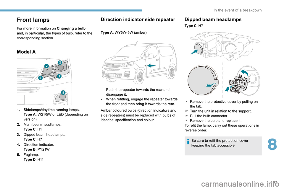
1.
Sidelamps/daytime running lamps.
Ty p e
A , W21/5W or LED (depending on
ve r s i o n)
2. Main beam headlamps.
Ty p e
C , H1
3. Dipped beam headlamps.
Ty p e
C , H7
4. Direction indicator.
Ty p e
B , PY21W
5. Foglamp.
Ty p e
D , H11
8
In the event of a breakdown
Page 200 of 312

198
Sidelamps/Daytime running lamps
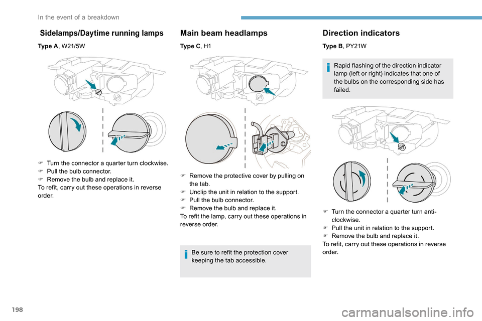
Ty p e A, W21/5W
F
T
urn the connector a quarter turn clockwise.
F
P
ull the bulb connector.
F
R
emove the bulb and replace it.
To refit, carry out these operations in reverse
o r d e r.
Main beam headlamps
Ty p e C , H1
F
R
emove the protective cover by pulling on
the tab.
F
U
nclip the unit in relation to the support.
F
P
ull the bulb connector.
F
R
emove the bulb and replace it.
To refit the lamp, carry out these operations in
reverse order.
Be sure to refit the protection cover
keeping the tab accessible.
Direction indicators
Ty p e B, PY21W
Rapid flashing of the direction indicator
lamp (left or right) indicates that one of
the bulbs on the corresponding side has
failed.
F
T
urn the connector a quarter turn anti-
clockwise.
F
P
ull the unit in relation to the support.
F
R
emove the bulb and replace it.
To refit, carry out these operations in reverse
o r d e r.
In the event of a breakdown