Page 598 of 682

Towing load/specification.......10-42
Trailertowing...............10-38
Towingatrailer................10-38
Towingyourvehicle..............6-17
Tow mode switch ...............2-65
Trailer Brake Controller Unit (TBCU) ....2-66
Transceiver HomeLink® Universal Transceiver . . .2-89, 2-90, 2-91, 2-92, 2-92, 2-93
Transfer case shif ting procedures .....5-46
Transmission
Driving with automatic transmission. .5-17
Travel (See registering a vehicle in another
country) .....................10-18
Trip odometer ..................2-7
Truckbox.................3-39,3-39
Truck - camper loading ...........10-36
Turn signal switch ...............2-53
U
Under seat storage bin .........2-73,2-77
Uniform tire quality grading ........10-64
USB/iPod® Charging Ports..........4-43
Using 4-wheel drive ..............5-45
V
Vanitymirror..................3-33
Variable voltage control system ......8-19
Vehicle dimensions and weights .....10-12
Vehicle Dynamic Control (VDC) OFF
switch......................2-60
Vehicle Dynamic Control (VDC) system . .5-59 Vehicle identification
.............10-18
Vehicle identification number (VIN) . . . .10-18
Vehicle identification number (VIN)
(Chassis number) ...............10-18
Vehicle identification number (VIN)
plate.......................10-18
Vehicle immobilizer system ......2-44,5-14
VehicleInformationDisplay.........2-26
Vehicle loading information ........10-23
Vehiclerecovery.............6-19,6-20
Vehicle security system ...........2-43
Vehicle security system (NISSAN Vehicle
Immobilizer System), engine start . .2-44, 5-14
Vents.......................4-29
Visors ......................3-32
Voltmeter ....................2-11
W
Warning Airbagwarninglight........1-81, 2-22
Anti-lock brake warning light ......2-17
Battery charge warning light ......2-19
Brakewarninglight............2-18
Door open warning light .........2-19
Engine oil pressure warning light ....2-19
Hazard warning flasher switch ......6-2
Loose fuel cap warning .........2-40
Lowfuelwarninglight.......2-22,2-37
Lowtirepressurewarninglight.....2-20
Low windshield-washer fluid warning
light......................2-38
Passenger air bag and status light . . .1-63
Passenger's seat belt warning light and
chime....................2-22 Seatbeltwarninglight.......1-18, 2-19
Supplemental air bag warning
light...................1-81, 2-22
Vehicle security system
.........2-43
Warning/indicator lights and audible
reminders ...............2-17,2-23
Warning labels (for SRS) .........1-80
Warning/indicator lights and audible
reminders .................2-17,2-23
Audible reminders ..........2-17,2-23
Indicatorlights............2-17,2-23
Warninglights ............2-17,2-23
Warninglights ..............2-17,2-23
Warning lights, indicator lights and audible
reminders ....................2-16
Warningsystemsswitch...........2-59
Weights
(See dimensions and weights) .......10-12
Wheels and tires ............8-35,10-11
Wheel/tire size .................10-11
When traveling or registering in another
country .....................10-18
Windows ....................2-83 Locking passengers' windows .....2-84
Powerrearwindows...........2-84
Powerwindows..............2-83
Rearpowerwindows...........2-84
Rearslidingwindow ...........2-86
Windshield-washer fluid ...........8-13
Windshield wiper blades ...........8-21
Wiper Wiper blades ................8-21
Wiper and washer switch ..........2-46
11-7
Page 611 of 682

∙If the “Low Fuel Pressure: See Owner’s
Manual” message is displayed on the
vehicle information display with the
engine running, complete a full key
cycle (turn the vehicle off and wait
2 minutes) and restart the vehicle. If
the message is still displayed or the
Malfunction Indicator Light is illumi-
nated af ter a full key cycle , it is rec-
ommended that you visit a NISSAN
dealer for service.
∙ For additional information on the lo-
cation of the fuel filter (stage 2), refer
to the “Engine compartment check
locations” in this section.
WARNING
∙ The fuel system (fuel pump, high pres- sure fuel lines, fuel rail, injectors) con-
tain very high pressure fuel. To avoid
the risk of personal injury or fire;
– Do not loosen any fittings while the engine is running.
– Wait at least 10 minutes af ter shut- ting down the engine before loos-
ening any fittings in the high-
pressure fuel system to allow
pressure to decrease to a lower
level. – Wear appropriate eye protection
and protective equipment as high-
pressure fuel spray can penetrate
the skin.
– Never smoke or allow sparks or flames (such as pilot lights, electri-
cal switches, or welding equip-
ment) in the work area. Never allow
diesel fuel to spill onto a hot ex-
haust manifold which can cause a
fire.
∙ Batteries can emit explosive gases. To reduce the possibility of personal in-
jury, always ventilate the compart-
ment before servicing the batteries.
To reduce the possibility of arcing, re-
move the negative (-) battery cable
first and attach the negative (-) bat-
tery cable last.
∙ When using a steam cleaner, wear safety glasses or a face shield, as well
as protective clothing. Hot steam can
cause serious personal injury.
∙ Wear appropriate eye and face pro- tection when using compressed air.
Flying debris and dirt can cause per-
sonal injury.
CAUTION
Clean all around the filter area before
disassembly. Dirt or contaminants can
damage the fuel system.
REMOVAL
WARNING
∙ Depending on the circumstance, fuelis flammable. When inspecting or per-
forming service or repairs on the fuel
system, to reduce the possibility of
fire and resulting severe personal in-
jury, death, or property damage, never
smoke or allow sparks or flames (such
as pilot lights, electrical switches, or
welding equipment) in the work area.
∙ Do not bleed the fuel system of a hot engine; this can result in fuel spilling
onto a hot exhaust manifold, which
can cause a fire.
1. Push the ignition switch to the OFF po- sition and wait 2 minutes before dis-
connecting the battery.
2. Disconnect the lef t and right side bat- teries.
Page 628 of 682
2 Instrument Panel
Meters and gauges..............................2-2
Warnings lights, indicator lights, meters
and gauges ..................................2-2 Vehicle information display warnings
and indicators
................................2-4
Resetting the oil control system ..............2-8
Page 629 of 682
WARNINGS LIGHTS, INDICATOR
LIGHTS, METERS AND GAUGES
These lights, meters and gauges are spe-
cific to the diesel engine.1. Low Diesel Exhaust Fluid (DEF) warning
light
2. Diesel Particulate Filter (DPF) warning light
3. Vehicle information display 4. Water in Fuel warning light
5. Malfunction warning light (red)
LIC3469
METERS AND GAUGES
2-2Instrument Panel
Page 648 of 682

WARNING
Always follow the instructions below.
Failure to do so could result in damage
to the charging system and cause per-
sonal injury.1. If the booster battery is in another ve- hicle, position the two vehicles to bring
their batteries near each other.
Do not allow the two vehicles to
touch. 2. Apply the parking brake. Move the shif t
lever to P (Park). Switch off all unneces-
sary electrical systems (lights, heater,
air conditioner, etc.).
3. Ensure the vent caps are level and tight.
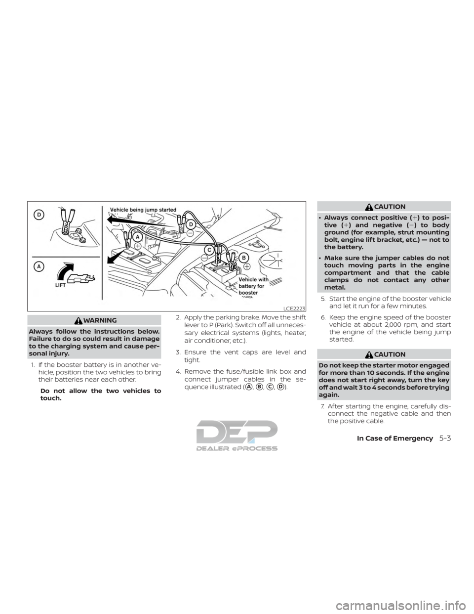
4. Remove the fuse/fusible link box and connect jumper cables in the se-
quence illustrated (
�A,�B,�C,�D).
CAUTION
∙ Always connect positive (�) to posi-tive ( �) and negative (�) to body
ground (for example, strut mounting
bolt, engine lif t bracket, etc.) — not to
the battery.
∙ Make sure the jumper cables do not touch moving parts in the engine
compartment and that the cable
clamps do not contact any other
metal.
5. Start the engine of the booster vehicle and let it run for a few minutes.
6. Keep the engine speed of the booster vehicle at about 2,000 rpm, and start
the engine of the vehicle being jump
started.
CAUTION
Do not keep the starter motor engaged
for more than 10 seconds. If the engine
does not start right away, turn the key
off and wait 3 to 4 seconds before trying
again.
7. Af ter starting the engine, carefully dis- connect the negative cable and then
the positive cable.
LCE2223
In Case of Emergency5-3