Page 431 of 682

7. Fit the square end of the jack rod intothe square hole of the wheel nut
wrench to form a handle.
8. Seat the T-shaped end of the jack rod into the T-shaped opening of the tire
winch. Apply pressure to keep the jack
rod engaged in the spare tire winch
and turn the jack rod counterclockwise
to lower the spare tire.
9. Once the spare tire is completely low- ered, reach under the vehicle, guide the
retainer chain through the center of
the tire and carefully slide the tire from
under the rear of the vehicle. 10. Securely store the flat tire beneath the
vehicle, from where the full size spare
was removed. To reinstall the wheel, re-
move the center cap (if so equipped)
and insert the retainer chain through
the wheel. Be sure the rubber spacer (if
so equipped) is centered on the wheel
before lif ting. Use the assembled jack-
ing rod to slowly rotate the winch clock-
wise to raise the wheel to the vehicle.
11. To reinstall the jack and tool kit, reverse steps 1 through 5.
NOTE:
Inspect the spacer every six years and
replace as necessary. It is recommended
that you visit a NISSAN dealer for this
service.
CAUTION
∙ Be sure to center the spare tire sus- pending plate on the wheel and then
lif t the spare tire.
∙ Failure to use the spacer may allow the chain to get stuck on the wheel
nut holes.
Getting the spare tire and tools
(Single Cab models)
1. Move the front passenger seat to ac- cess the tools. For additional informa-
tion about seat functions, refer to “
Seats” in the “Safety–Seats, seat belts
and supplemental restraint system”
section of this manual.
WCE0151
6-6In case of emergency
Page 433 of 682

and insert the retainer chain through")
10. Securely store the flat tire beneath thevehicle, from where the full size spare
was removed. To reinstall the wheel, re-
move the center cap (if so equipped)
and insert the retainer chain through
the wheel. Be sure the rubber spacer (if
so equipped) is centered on the wheel
before lif ting. Use the assembled jack-
ing rod to slowly rotate the winch clock-
wise to raise the wheel to the vehicle.
11. To reinstall the jack and tool kit, reverse steps 1 through 5.
NOTE:
Inspect the spacer every six years and
replace as necessary. It is recommended
that you visit a NISSAN dealer for this
service.
CAUTION
∙ Be sure to center the spare tire sus- pending plate on the wheel and then
lif t the spare tire.
∙ Failure to use the spacer may allow the chain to get stuck on the wheel
nut holes.
Getting the spare tire and tools
(King Cab® models not equipped
with rear seat)
1. Open the passenger side rear door and remove the lid from the tool storage
compartment. 2. Release the straps
�A.
3. Remove the tire stopper bag
�B.
4. Lif t the storage cover
�Cto access the
jack.
5. Remove the tool kit and jack.
LCE2327LCE2328
6-8In case of emergency
Page 434 of 682
. Pass the
T-shaped end of the jack rod through
the op")
6. Assemble the pieces of the jack rod.Find the oval-shaped opening above
the license plate, slightly to the lef t of
the middle (driver’s side). Pass the
T-shaped end of the jack rod through
the opening and direct it toward the
spare tire winch, located directly above
the spare tire.
CAUTION
Do not insert the jack rod straight as it is
designed to be inserted at an angle as
shown. 7. Fit the square end of the jack rod into
the square hole of the wheel nut
wrench to form a handle.
8. Seat the T-shaped end of the jack rod into the T-shaped opening of the tire
winch. Apply pressure to keep the jack
rod engaged in the spare tire winch
and turn the jack rod counterclockwise
to lower the spare tire.
9. Once the spare tire is completely low- ered, reach under the vehicle, guide the
retainer chain through the center of
the tire and carefully slide the tire from
under the rear of the vehicle. 10. Securely store the flat tire beneath the
vehicle, from where the full size spare
was removed. To reinstall the wheel, re-
move the center cap (if so equipped)
and insert the retainer chain through
the wheel. Be sure the rubber spacer (if
so equipped) is centered on the wheel
before lif ting. Use the assembled jack-
ing rod to slowly rotate the winch clock-
wise to raise the wheel to the vehicle.
11. To reinstall the jack and tool kit, reverse steps 1 through 5.
NOTE:
Inspect the spacer every six years and
replace as necessary. It is recommended
that you visit a NISSAN dealer for this
service.
CAUTION
∙ Be sure to center the spare tire sus- pending plate on the wheel and then
lif t the spare tire.
∙ Failure to use the spacer may allow the chain to get stuck on the wheel
nut holes.
WCE0150WCE0151
In case of emergency6-9
Page 490 of 682
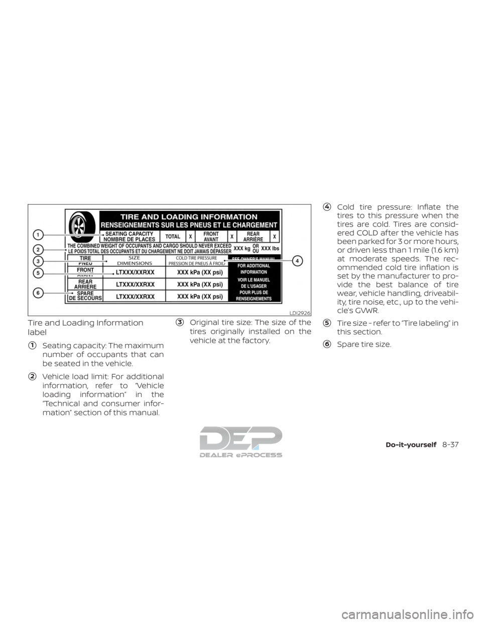
Tire and Loading Information
label
�1Seating capacity: The maximum
number of occupants that can
be seated in the vehicle.
�2Vehicle load limit: For additional
information, refer to “Vehicle
loading information” in the
“Technical and consumer infor-
mation” section of this manual.
�3Original tire size: The size of the
tires originally installed on the
vehicle at the factory.
�4Cold tire pressure: Inflate the
tires to this pressure when the
tires are cold. Tires are consid-
ered COLD af ter the vehicle has
been parked for 3 or more hours,
or driven less than 1 mile (1.6 km)
at moderate speeds. The rec-
ommended cold tire inflation is
set by the manufacturer to pro-
vide the best balance of tire
wear, vehicle handling, driveabil-
ity, tire noise, etc., up to the vehi-
cle’s GVWR.
�5Tire size - refer to “Tire labeling” in
this section.
�6Spare tire size.
LDI2926
Do-it-yourself8-37
Page 491 of 682

Checking tire pressure
1. Remove the valve stem cap fromthe tire.
2. Press the pressure gauge squarely onto the valve stem. Do
not press too hard or force the
valve stem sideways, or air will
escape. If the hissing sound of air
escaping from the tire is heard
while checking the pressure, re-
position the gauge to eliminate
this leakage. 3. Remove the gauge.
4. Read the tire pressure on the
gauge stem and compare to the
specification shown on the Tire
and Loading Information label.
5.
Add air to the tire as needed. If too
much air is added, press the core
of the valve stem briefly with the
tip of the gauge stem to release
pressure. Recheck the pressure
and add or release air as needed.
6. Install the valve stem cap.
7. Check the pressure of all other tires, including the spare.
Size Cold Tire Inflation
Pressure
Front Original
Tire:
265/70R18 270 kPa, 39 psi
P265/70R18 250 kPa, 36 psi
P275/60R20 250 kPa, 36 psi
P275/70R18 240 kPa, 35 psi
LT245/75R17 450 kPa, 65 psi
LT275/65R18 450 kPa, 65 psi
LT265/60R20 450 kPa, 65 psi
Size Cold Tire Inflation
Pressure
Rear Original
Tire:
265/70R18 270 kPa, 39 psi
P265/70R18 250 kPa, 36 psi
P275/60R20 250 kPa, 36 psi
P275/70R18 240 kPa, 35 psi
LT245/75R17 500 kPa, 73 psi
LT275/65R18 450 kPa, 65 psi
LT265/60R20 480 kPa, 70 psi
Spare Tire: Full size
LDI0393
8-38Do-it-yourself
Page 492 of 682
TIRE LABELING
Federal law requires tire manufac-
turers to place standardized infor-
mation on the sidewall of all tires.
This information identifies and de-
scribes the fundamental character-
istics of the tire and also provides the
Tire Identification Number (TIN) for
safety standard certification. The TIN
can be used to identif y the tire in
case of a recall.
�1Tire size (example: LT215/65R15
95H)
1. LT: The “LT” indicates the tire is designed for light truck vehicles
(not all tires have this informa-
tion).
2. Three-digit number (215): This number gives the width in milli-
meters of the tire from sidewall
edge to sidewall edge. 3. Two-digit number (65): This
number, known as the aspect
ratio, gives the tire’s ratio of
height to width.
4. R: The “R” stands for radial.
5. Two-digit number (15): This num- ber is the wheel or rim diameter
in inches.
ExampleWDI0394
Example
LDI2043
Do-it-yourself8-39
Page 493 of 682
6. Two- or three-digit number (95):This number is the tire’s load in-
dex. It is a measurement of how
much weight each tire can sup-
port. You may not find this infor-
mation on all tires because it is
not required by law.
7. H: Tire speed rating. You should not drive the vehicle faster than
the tire speed rating.
�2TIN (Tire Identification Number)
for a new tire (example: DOT XX XX
XXX XXXX)
1. DOT: Abbreviation for the “De- partment Of Transportation”.
The symbol can be placed
above, below or to the lef t or
right of the Tire Identification
Number.
2. Two-digit code: Manufacturer’s identification mark. 3. Two-digit code: Tire size.
4. Three-digit code: Tire type code
(Optional).
5. Four numbers represent the week and year the tire was built.
For example, the numbers 3103
means the 31st week of 2003. If
these numbers are missing then
look on the other sidewall of the
tire.
Example
LDI2786
8-40Do-it-yourself
Page 494 of 682

�3Tire ply composition and material
The number of layers or plies of
rubber-coated fabric in the tire. Tire
manufacturers also must indicate
the materials in the tire, which in-
clude steel, nylon, polyester and oth-
ers.
�4Maximum permissible inflation
pressure
This number is the greatest amount
of air pressure that should be put in
the tire. Do not exceed the maximum
permissible inflation pressure.
�5Maximum load rating
This number indicates the maxi-
mum load in kilograms and pounds
that can be carried by the tire. When
replacing the tires on the vehicle, al-
ways use a tire that has the same
load rating as the factory installed
tire.
�6Term of “tubeless” or “tube type”
Indicates whether the tire requires
an inner tube (“tube type”) or not
(“tubeless”).
�7The word “radial”
The word “radial” is shown if the tire
has radial structure.
�8Manufacturer or brand name
Manufacturer or brand name is
shown.
Other Tire-related Terminology
In addition to the many terms that
are defined throughout this section,
Intended Outboard Sidewall is (1) the
sidewall that contains a whitewall,
bears white lettering or bears
manufacturer, brand, and/or model
name molding that is higher or
deeper than the same molding on
the other sidewall of the tire, or (2)
the outward facing sidewall of an
asymmetrical tire that has a particu-
lar side that must always face out-
ward when mounted on a vehicle.
TYPES OF TIRES
WARNING
∙ When changing or replacing tires, be sure all four tires are of the same type
(i.e., Summer, All Season or Snow) and
construction. A NISSAN dealer may be
able to help you with information
about tire type, size, speed rating and
availability.
∙ Replacement tires may have a lower speed rating than the factory
equipped tires, and may not match
the potential maximum vehicle
speed. Never exceed the maximum
speed rating of the tire.
∙ Replacing tires with those not origi- nally specified by NISSAN could affect
the proper operation of the low tire
pressure warning system.
∙ For additional information regarding tires, refer to “Important Tire Safety
Information” (US) or “Tire Safety Infor-
mation” (Canada) in the Warranty In-
formation Booklet.
Do-it-yourself8-41

:This number is the tire’s load in-
dex. It is a measurement of how
much weight each tire can sup-
port. You may not find this infor-
mation on all tires because it")