2019 NISSAN ROGUE SPORT mirror
[x] Cancel search: mirrorPage 155 of 500
.The ignition switch is placed in the
OFF position. (model with Intelligent
Key system)
The interior light timer will be cancelled
when:
. The driver’s door is locked.
. The ignition switch is placed in the ON
position.
When the switch is in the OFF position
,
the room light does not illuminate, re-
gardless of any condition.
SIC3869
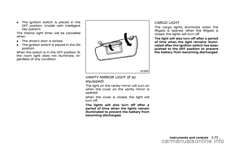
VANITY MIRROR LIGHT (if so
equipped)
The light on the vanity mirror will turn on
when the cover on the vanity mirror is
opened.
When the cover is closed, the light will
turn off.
The lights will also turn off after a
period of time when the lights remain
illuminated to prevent the battery from
becoming discharged.
CARGO LIGHT
The cargo lights illuminate when the
liftgate is opened. When the liftgate is
closed, the lights will turn off.
The light will also turn off after a period
of time when the light remains illumi-
nated after the ignition switch has been
pushed to the OFF position to prevent
the battery from becoming discharged.
Instruments and controls2-75
Page 161 of 500
3 Pre-driving checks and adjustments
Keys ........................................................................\
................................. 3-2NISSAN Vehicle Immobilizer System key (if
so equipped) ........................................................................\
...... 3-2
Intelligent Key (if so equipped) ................................... 3-3
Doors ........................................................................\
.............................. 3-5 Locking with key .................................................................... 3-5
Locking with inside lock knob ..................................... 3-6
Locking with power door lock switch ................... 3-7
Automatic door locks ......................................................... 3-7
Child safety rear door lock ............................................. 3-7
Remote keyless entry system (if so equipped) ...... 3-8 How to use remote keyless entry system ......... 3-9
Intelligent Key system (if so equipped) .................... 3-11
Intelligent Key operating range .............................. 3-13
Door locks/unlocks precaution ............................... 3-13
Intelligent Key operation .............................................. 3-14
Battery saver system ....................................................... 3-16
Warning lights and audible reminders .............. 3-16
Troubleshooting guide ................................................... 3-17
How to use remote keyless entry function ...... 3-19 Remote engine start (if so equipped) ...................... 3-23
Remote engine start operating range ............ 3-23
Remote starting the engine .................................... 3-23
Extending engine run time ....................................... 3-24
Canceling a remote engine start ........................ 3-24
Conditions the remote engine start will
not work ........................................................................\
.......... 3-24
Hood ........................................................................\
............................ 3-25
Liftgate ........................................................................\
...................... 3-26 Liftgate release lever ..................................................... 3-27
Fuel-filler door ........................................................................\
..... 3-28 Opening the fuel-filler door ...................................... 3-28
Fuel-filler cap ....................................................................... 3-28
Tilt/telescopic steering ........................................................ 3-30 Tilt or telescopic operation ...................................... 3-31
Sun visors ........................................................................\
................ 3-31
Mirrors ........................................................................\
...................... 3-32 Inside mirror ........................................................................\
. 3-32
Outside mirrors .................................................................. 3-33
Vanity mirror ........................................................................\
3-34
Page 192 of 500
3-32Pre-driving checks and adjustments
SPA2447
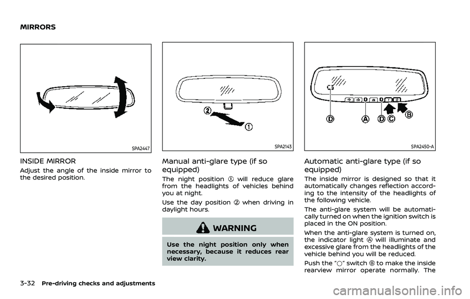
INSIDE MIRROR
Adjust the angle of the inside mirror to
the desired position.
SPA2143
Manual anti-glare type (if so
equipped)
The night positionwill reduce glare
from the headlights of vehicles behind
you at night.
Use the day position
when driving in
daylight hours.
WARNING
Use the night position only when
necessary, because it reduces rear
view clarity.
SPA2450-A
Automatic anti-glare type (if so
equipped)
The inside mirror is designed so that it
automatically changes reflection accord-
ing to the intensity of the headlights of
the following vehicle.
The anti-glare system will be automati-
cally turned on when the ignition switch is
placed in the ON position.
When the anti-glare system is turned on,
the indicator light
will illuminate and
excessive glare from the headlights of the
vehicle behind you will be reduced.
Push the “*” switch
to make the inside
rearview mirror operate normally. The
MIRRORS
Page 193 of 500
indicator light will turn off. Push the “I”
switchto turn the system on.
Do not allow any object to cover the
sensors
or apply glass cleaner on
them. Doing so will reduce the sensitiv-
ity of the sensor, resulting in improper
operation.
For the HomeLink® Universal Transceiver
operation, see “HomeLink® Universal
Transceiver” (P.2-76).
OUTSIDE MIRRORS
WARNING
Objects viewed in the outside mirror
on the passenger side are closer
than they appear. Be careful when
moving to the right. Using only this
mirror could cause an accident. Use
the inside mirror or glance over your
shoulder to properly judge distances
to other objects.
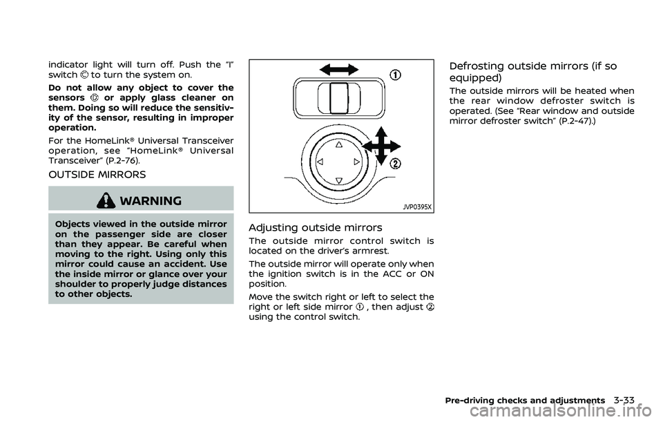
JVP0395X
Adjusting outside mirrors
The outside mirror control switch is
located on the driver’s armrest.
The outside mirror will operate only when
the ignition switch is in the ACC or ON
position.
Move the switch right or left to select the
right or left side mirror
, then adjustusing the control switch.
Defrosting outside mirrors (if so
equipped)
The outside mirrors will be heated when
the rear window defroster switch is
operated. (See “Rear window and outside
mirror defroster switch” (P.2-47).)
Pre-driving checks and adjustments3-33
Page 194 of 500
3-34Pre-driving checks and adjustments
SPA1829
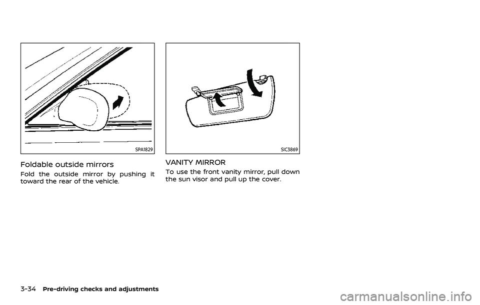
Foldable outside mirrors
Fold the outside mirror by pushing it
toward the rear of the vehicle.
SIC3869
VANITY MIRROR
To use the front vanity mirror, pull down
the sun visor and pull up the cover.
Page 197 of 500
WARNING
.Failure to follow the warnings
and instructions for proper use
of the RearView Monitor could
result in serious injury or death.
. RearView Monitor is a conveni-
ence feature and is not a sub-
stitute for proper backing. Always
turn and look out the windows,
and check mirrors to be sure that
it is safe to move before operat-
ing the vehicle. Always back up
slowly.
. The system is designed as an aid
to the driver in showing large
stationary objects directly behind
the vehicle, to help avoid dama-
ging the vehicle.
. The distance guide line and the
vehicle width line should be used
as a reference only when the
vehicle is on a level paved sur-
face. The distance viewed on the
monitor is for reference only and
may be different than the actual
distance between the vehicle and
displayed objects.
CAUTION
Do not scratch the camera lens when
cleaning dirt or snow from the front
of the camera.
The RearView Monitor system automati-
cally shows a rear view of the vehicle
when the shift lever is placed in the R
(Reverse) position.
The radio can still be heard while the
RearView Monitor is active.
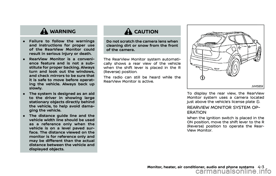
JVH1585X
To display the rear view, the RearView
Monitor system uses a camera located
just above the vehicle’s license plate
.
REARVIEW MONITOR SYSTEM OP-
ERATION
When the ignition switch is placed in the
ON position, move the shift lever to the R
(Reverse) position to operate the Rear-
View Monitor.
Monitor, heater, air conditioner, audio and phone systems4-3
Page 202 of 500
4-8Monitor, heater, air conditioner, audio and phone systems
HOW TO TURN ON AND OFF PRE-
DICTIVE COURSE LINES
To turn the predictive course lines on and
off when the shift lever is in the P (Park)
position, perform the following operation.
1. Push the MENU button
2. Touch the “Settings” key and thentouch the “Camera” key.
3. Touch the “Predictive Course Lines” key to turn the feature ON or OFF.
Pushing the CAMERA button while the
shift lever is in the R (Reverse) position
can also turn on and off the predictive
course lines.
REARVIEW MONITOR SYSTEM LIM-
ITATIONS
WARNING
Listed below are the system limita-
tions for RearView Monitor. Failure to
operate the vehicle in accordance
with these system limitations could
result in serious injury or death.
. The system cannot completely
eliminate blind spots and may
not show every object. .
Underneath the bumper and the
corner areas of the bumper can-
not be viewed on the RearView
Monitor because of its monitoring
range limitation. The system will
not show small objects below the
bumper, and may not show ob-
jects close to the bumper or on
the ground.
. Objects viewed in the RearView
Monitor differ from actual dis-
tance because a wide-angle lens
is used.
. Objects in the RearView Monitor
will appear visually opposite
compared to when viewed in the
rearview and outside mirrors.
. Use the displayed lines as a re-
ference. The lines are highly af-
fected by the number of
occupants, fuel level, vehicle po-
sition, road conditions and road
grade.
. Make sure that the liftgate is
securely closed when backing up.
. Do not put anything on the rear-
view camera. The rearview cam-
era is installed above the license
plate. .
When washing the vehicle with
high-pressure water, be sure not
to spray it around the camera.
Otherwise, water may enter the
camera unit causing water con-
densation on the lens, a malfunc-
tion, fire or an electric shock.
. Do not strike the camera. It is a
precision instrument. Otherwise,
it may malfunction or cause da-
mage resulting in a fire or an
electric shock.
The following are operating limitations
and do not represent a system malfunc-
tion:
. When the temperature is extremely
high or low, the screen may not clearly
display objects.
. When strong light directly shines on
the camera, objects may not be dis-
played clearly.
. Vertical lines may be seen in objects
on the screen. This is due to strong
reflected light from the bumper.
. The screen may flicker under fluores-
cent light.
. The colors of objects on the RearView
Monitor may differ somewhat from
the actual color of objects.
Page 205 of 500
CAUTION
Do not scratch the lens when clean-
ing dirt or snow from the front of the
camera.
The Intelligent Around View® Monitor
system is designed as an aid to the driver
in situations such as slot parking or
parallel parking.
The monitor displays various views of the
position of the vehicle in a split screen
format. Not all views are available at all
times.
Available views:
. Front view
The view to the front of the vehicle.
. Rear view
The view to the rear of the vehicle.
. Bird’s-eye view
The views to the vehicle from above.
. Front-side view
The view around and ahead of the
front passenger’s side wheel.
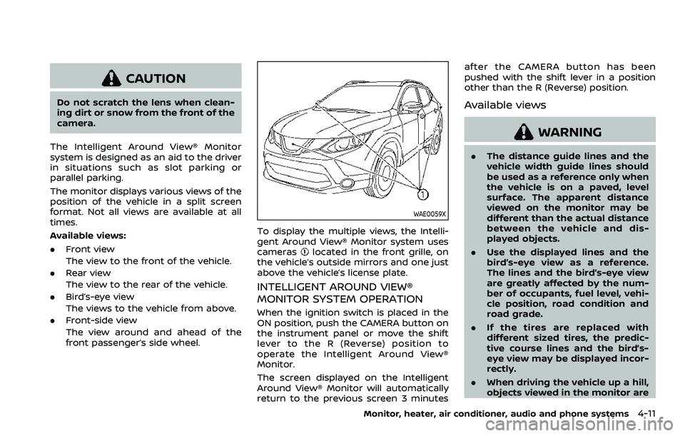
WAE0059X
To display the multiple views, the Intelli-
gent Around View® Monitor system uses
cameras
located in the front grille, on
the vehicle’s outside mirrors and one just
above the vehicle’s license plate.
INTELLIGENT AROUND VIEW®
MONITOR SYSTEM OPERATION
When the ignition switch is placed in the
ON position, push the CAMERA button on
the instrument panel or move the shift
lever to the R (Reverse) position to
operate the Intelligent Around View®
Monitor.
The screen displayed on the Intelligent
Around View® Monitor will automatically
return to the previous screen 3 minutes after the CAMERA button has been
pushed with the shift lever in a position
other than the R (Reverse) position.
Available views
WARNING
.
The distance guide lines and the
vehicle width guide lines should
be used as a reference only when
the vehicle is on a paved, level
surface. The apparent distance
viewed on the monitor may be
different than the actual distance
between the vehicle and dis-
played objects.
. Use the displayed lines and the
bird’s-eye view as a reference.
The lines and the bird’s-eye view
are greatly affected by the num-
ber of occupants, fuel level, vehi-
cle position, road condition and
road grade.
. If the tires are replaced with
different sized tires, the predic-
tive course lines and the bird’s-
eye view may be displayed incor-
rectly.
. When driving the vehicle up a hill,
objects viewed in the monitor are
Monitor, heater, air conditioner, audio and phone systems4-11