Page 170 of 476

WARNING
∙ Do not use the HomeLink® UniversalTransceiver with any garage door
opener that lacks safety stop and re-
verse features as required by federal
safety standards. (These standards
became effective for opener models
manufactured af ter April 1, 1982). A
garage door opener which cannot de-
tect an object in the path of a closing
garage door and then automatically
stop and reverse, does not meet cur-
rent federal safety standards. Using a
garage door opener without these
features increases the risk of serious
injury or death.
∙ During the programming procedure your garage door or security gate will
open and close (if the transmitter is
within range). Make sure that people
or objects are clear of the garage door,
gate, etc. that you are programming. ∙ Your vehicle’s engine should be
turned off while programming the
HomeLink® Universal Transceiver. Do
not breathe exhaust gases; they con-
tain colorless and odorless carbon
monoxide. Carbon monoxide is dan-
gerous. It can cause unconsciousness
or death.
PROGRAMMING HOMELINK®
If you have any questions or are having
difficulty programming your HomeLink®
buttons, refer to the HomeLink® web site at:
www.homelink.com or call 1-800-355-3515.
NOTE:
Place the ignition switch in the ACC posi-
tion when programming HomeLink®. It is
also recommended that a new battery
be placed in the hand-held transmitter
of the device being programmed to
HomeLink® for quicker programming
and accurate transmission of the radio
frequency. 1. Position the end of your hand-held
transmitter 1–3 in (2–8 cm) away from
the HomeLink® surface, keeping the
HomeLink® indicator light
�1in view.
Page 182 of 476
WARNING
∙ Radio waves could adversely affectelectric medical equipment. Those
who use a pacemaker should contact
the electric medical equipment
manufacturer for the possible influ-
ences before use.
∙ The Intelligent Key transmits radio waves when the buttons are pressed.
The FAA advises the radio waves may
affect aircraf t navigation and com-
munication systems. Do not operate
the Intelligent Key while on an air-
plane. Make sure the buttons are not
operated unintentionally when the
unit is stored for a flight.
The Intelligent Key can operate all the door
locks using the remote control function or
pushing the request switch on the vehicle
without taking the key out from a pocket or
purse. The operating environment and/or
conditions may affect the Intelligent Key
operation.
Be sure to read the following before using
the Intelligent Key.
Page 195 of 476
WARNING
∙Radio waves could adversely affect elec-
tric medical equipment. Those who use a
pacemaker should contact the electric
medical equipment manufacturer for
the possible influences before use.
∙ The Intelligent Key transmits radio waves when the buttons are pressed.
The FAA advises the radio waves may
affect aircraf t navigation and com-
munication systems. Do not operate
the Intelligent Key while on an air-
plane. Make sure the buttons are not
operated unintentionally when the
unit is stored for a flight.
The Intelligent Key can operate all the door
locks using the remote control function. The
operating environment and/or conditions
may affect the Intelligent Key operation.
Be sure to read the following before using
the Intelligent Key.
Page 206 of 476
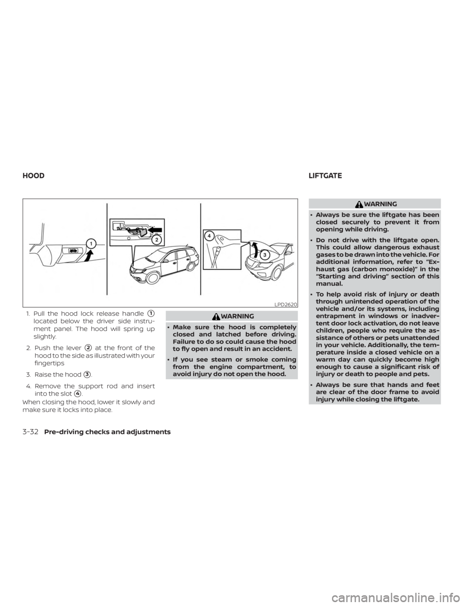
1. Pull the hood lock release handle�1
located below the driver side instru-
ment panel. The hood will spring up
slightly.
2. Push the lever
�2at the front of the
hood to the side as illustrated with your
fingertips
3. Raise the hood
�3.
4. Remove the support rod and insert into the slot
�4.
When closing the hood, lower it slowly and
make sure it locks into place.
Page 219 of 476
VANITY MIRRORS
To access the vanity mirror, pull the sun
visor down and flip open the mirror cover.
Some vanity mirrors are illuminated (if so
equipped) and turn on when the mirror
cover is open.CARD HOLDER
To access the card holder located on the
ceiling, pull the driver’s side sun visor down
and slide the card into the card holder
�1.
Do not view information while operating
the vehicle.
MANUAL ANTI-GLARE REARVIEW
MIRROR (if so equipped)
Use the night position�1to reduce glare
from the headlights of vehicles behind you
at night.
Use the day position
�2when driving in
daylight hours.
Page 236 of 476

∙ When washing the vehicle with highpressure water, be sure not to spray it
around the camera. Otherwise, water
may enter the camera unit causing
water condensation on the lens, a
malfunction, fire or an electric shock.
∙ Do not strike the camera. It is a preci- sion instrument. Otherwise, it may
malfunction or cause damage result-
ing in a fire or an electric shock.
The following are operating limitations and
do not represent a system malfunction: ∙ When the temperature is extremely high or low, the screen may not clearly
display objects.
∙ When strong light directly shines on the camera, objects may not be displayed
clearly.
∙ Vertical lines may be seen in objects on the screen. This is due to strong re-
flected light from the bumper.
∙ The screen may flicker under fluores- cent light.
∙ The colors of objects on the RearView Monitor may differ somewhat from the
actual color of objects. ∙ Objects on the monitor may not be
clear in a dark environment.
∙ There may be a delay when switching between views.
∙ If dirt, rain or snow accumulate on the camera, the RearView Monitor may not
display objects clearly. Clean the cam-
era.
∙ Do not use wax on the camera lens. Wipe off any wax with a clean cloth
dampened with a diluted mild cleaning
agent, then wipe with a dry cloth.
SYSTEM MAINTENANCE
Page 241 of 476

Bird’s-eye view
The bird’s-eye view shows the overhead
view of the vehicle, which helps confirm the
vehicle position and the predicted course
to a parking space.
The vehicle icon
�1shows the position of
the vehicle. Note that the apparent dis-
tance between objects viewed in the bird’s-
eye view may differ somewhat from the
actual distance to the vehicle.
The areas that the cameras cannot cover
�2are indicated in black. The non-viewable area
�2is highlighted in
yellow for several seconds af ter the bird’s-
eye view is displayed. It will be shown only
the first time af ter the ignition switch is
placed in the ON position.
In addition, the non-viewable corners are
displayed in red and blink for the first 3 sec-
onds
�3to remind the driver to be cau-
tious.
Predicted course lines
�4indicate the pre-
dicted course when operating the vehicle.
The predicted course lines will be displayed
on the monitor when the steering wheel is
turned. The predicted course lines will move depending on how much the steer-
ing wheel is turned and will not be dis-
played while the steering wheel is in the
neutral position.
When the monitor displays the front view
and the steering wheel turns about 90 de-
grees or less from the neutral position, the
two green predicted course lines are
shown in front of the vehicle.
When the steering wheel turns about 90
degrees or more, one green predicted
course line is shown in front of the vehicle
and the other predicted course line is
shown at the side of the vehicle.
When the monitor displays the rear view,
the predicted course lines are shown at the
back of the vehicle.
Page 272 of 476

Additional information:∙ When replacing a wheel without the TPMS such as the spare tire, the TPMS
does not monitor the tire pressure of
the spare tire.
∙ The TPMS will activate only when the vehicle is driven at speeds above
16 mph (25 km/h). Also, this system may
not detect a sudden drop in tire pres-
sure (for example, a flat tire while driv-
ing).
∙ The low tire pressure warning light does not automatically turn off when the tire
pressure is adjusted. Af ter the tire is in-
flated to the recommended pressure,
the vehicle must be driven at speeds
above 16 mph (25 km/h) to activate the
TPMS and turn off the low tire pressure
warning light. Use a tire pressure gauge
to check the tire pressure.
∙ The “Tire Pressure Low - Add Air” warn- ing appears in the vehicle information
display when the low tire pressure
warning light is illuminated and low tire
pressure is detected. The “Tire Pressure
Low - Add Air” warning turns off when
the low tire pressure warning light turns
off. ∙ The “Tire Pressure Low - Add Air” warn-
ing appears each time the ignition
switch is placed in the on position as
long as the low tire pressure warning
light remains illuminated.
∙ The “Tire Pressure Low - Add Air” warn- ing does not appear if the low tire pres-
sure warning light illuminates to indi-
cate a TPMS malfunction.
∙ Tire pressure rises and falls depending on the heat caused by the vehicle’s op-
eration and the outside temperature.
Do not reduce the tire pressure af ter
driving because the tire pressure rises
af ter driving. Low outside temperature
can lower the temperature of the air
inside the tire which can cause a lower
tire inflation pressure. This may cause
the low tire pressure warning light to
illuminate. If the warning light illumi-
nates, check the tire pressure for all four
tires.
∙ The Tire and Loading Information label is located in the driver’s door opening. ∙ You can also check the pressure of all
tires (except the spare tire) on the ve-
hicle information display screen. The or-
der of the tire pressure figures dis-
played on the screen corresponds with
the actual order of the tire position.
For additional information, refer to “Low tire
pressure warning light” in the “Instruments
and controls” section and “Tire Pressure
Monitoring System (TPMS)” in the “In case of
emergency” section of this manual.


 and turn on when the mirror
cover is open.CARD")