Page 74 of 516
– Do not install a child restraint sys-tem on the passenger’s side jump
seat without unfolding the seat
extender.
– For forward-facing child seats and boosters, DO NOT install if the child
restraint base extends past the
forward edge of the driver’s side
seat cushion.
For additional information, refer to all Warn-
ings and Cautions in the “Child safety” and
“Child restraints” sections of this manual
before installing a child restraint.
Do not use the lower anchors if the com-
bined weight of the child and the child re-
straint exceeds 65 lbs. (29.5 kg). If the com-
bined weight of the child and the child
restraint is greater than 65 lbs. (29.5 kg), use
the vehicle’s seat belt (not the lower an-
chors) to install the child restraint. Be sure
to follow the child restraint manufacturer’s
instructions for installation.
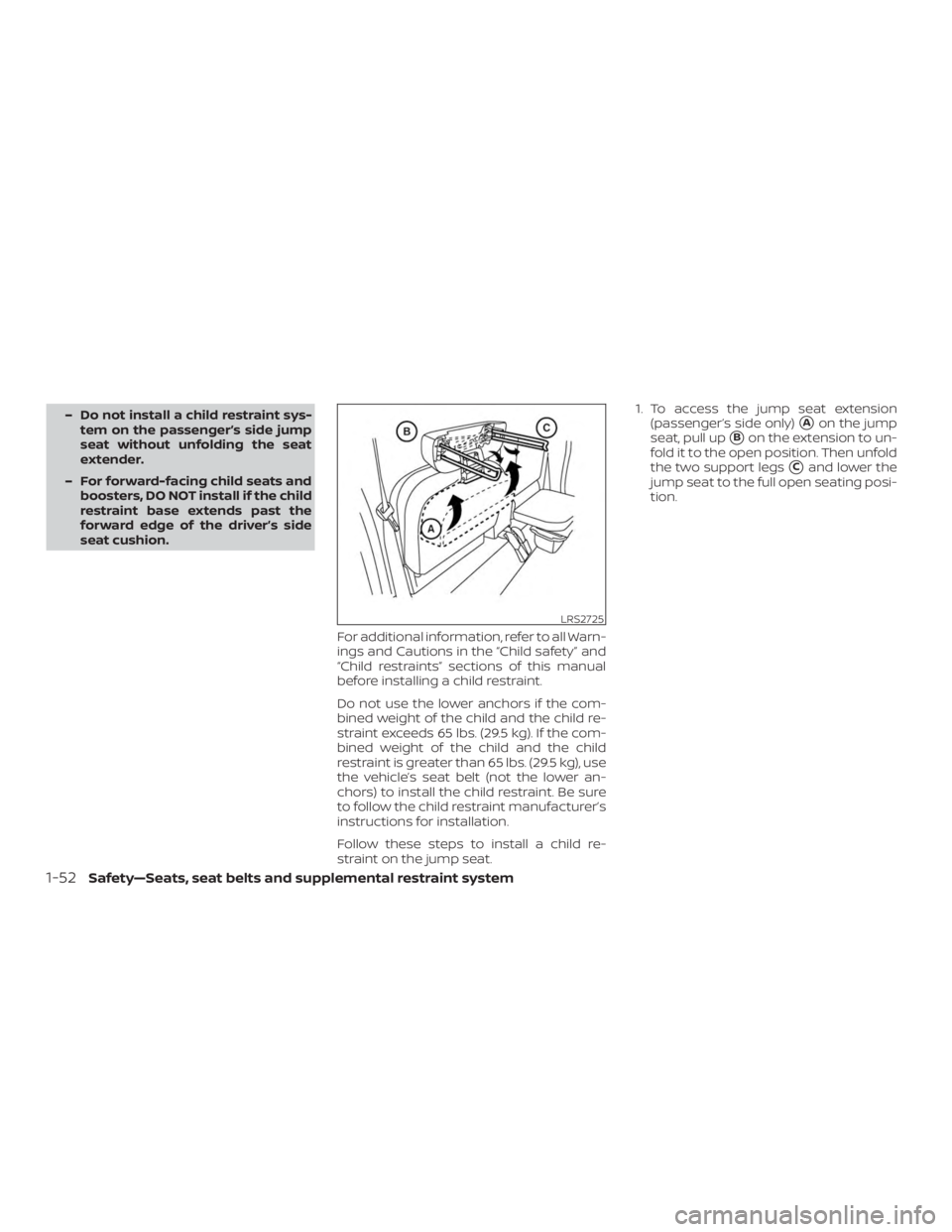
Follow these steps to install a child re-
straint on the jump seat. 1. To access the jump seat extension
(passenger’s side only)�Aon the jump
seat, pull up
�Bon the extension to un-
fold it to the open position. Then unfold
the two support legs
�Cand lower the
jump seat to the full open seating posi-
tion.
Page 122 of 516
DTE display will change to “---” when the
fuel level in the tank is getting low, prior to
the fuel gauge reaching 0 (Empty).
NOTE:∙ The DTE value af ter refill is estimated
based on recent fuel economy and
amount of fuel added.
∙ If a small amount of fuel is added, or
the ignition is on during refueling, the
display may not be updated.
∙ Conditions that affect the fuel
economy will also affect the esti-
mated DTE value (city/highway driv-
ing, idle time, remote start time, ter-
rain, seasonal weather, added vehicle
weight, added deflectors, roof racks,
etc.).
ENGINE OIL PRESSURE GAUGE (if
so equipped)
The gauge indicates the engine lubrication
system oil pressure while the engine is run-
ning. The needle should be in the middle of
the gauge when the engine is running.
Page 163 of 516
Always evenly distribute the cargo on the
tubular roof rack.The maximum total
load is 125 lbs. (56 kg) evenly distributed.
Be careful that your vehicle does not ex-
ceed the Gross Vehicle Weight Rating
(GVWR) or the Gross Axle Weight Ratings
(GAWR front and rear). The GVWR and GAWR
are located on the F.M.V.S.S. label (located
on the driver’s side door jamb pillar). For
additional information, refer to “Vehicle
loading information” in the “Technical and
consumer information” section of this
manual.
The front crossbar can be adjusted or re-
moved. Use the TORX® driver provided in
the tool kit to loosen both crossbar adjust-
ing screws.
To adjust:
1. Loosen the adjusting screws with the TORX® driver
�1by turning counter-
clockwise
�A.
2. When the clamp is loosened, move the crossbar so the cargo can be posi-
tioned on the crossbar
�B.
3. Tighten the crossbar adjusting screws with the TORX® driver by turning clock-
wise.
4. Secure the cargo with rope. 5. Always check the tightness of the
crossbar adjusting screws.
To remove: 1. Loosen the adjusting screws with the TORX® driver
�1by turning counter-
clockwise
�A.
2. Rotate the clamps
�C.
3. Remove the crossbar.
4. Reverse to install.
5. Always check the tightness of the crossbar adjusting screws.
If you hear wind noise coming from the roof
rack while driving, adjust the roof rack
crossbar to the neutral position.
MANUAL WINDOWS (if so
equipped)
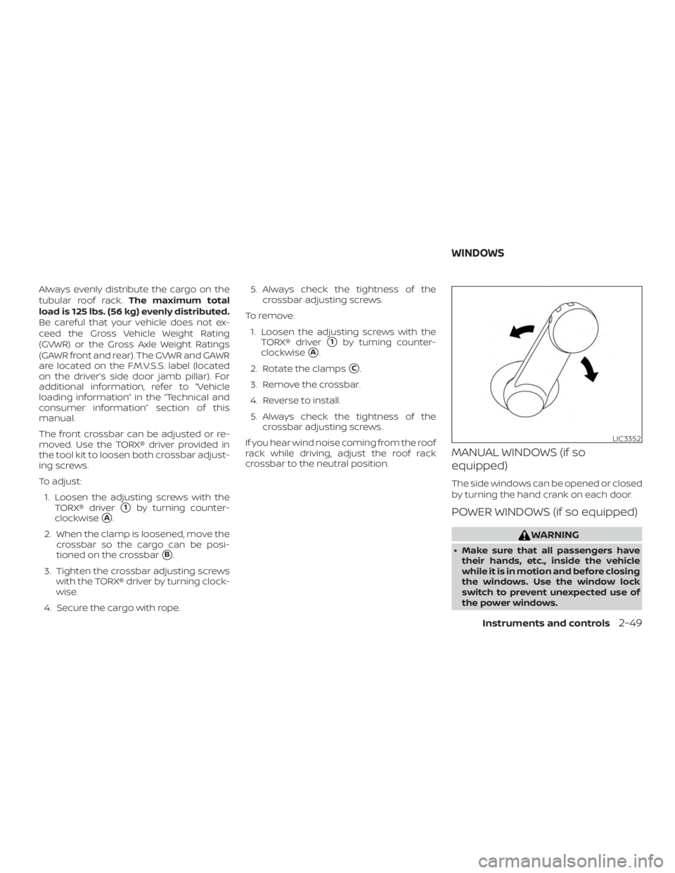
The side windows can be opened or closed
by turning the hand crank on each door.
POWER WINDOWS (if so equipped)
Page 198 of 516
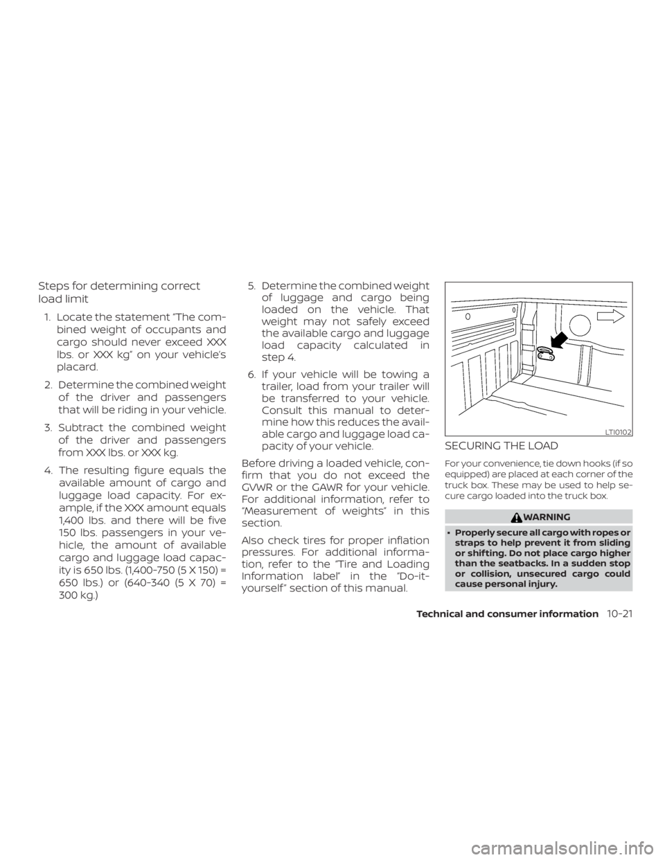
TIE DOWN HOOKS (if so equipped)
For your convenience, tie down hooks are
placed at each corner of the truck box.
These may be used to help secure cargo
loaded into the truck box.∙ The weight of the cargo load must be evenly distributed over both the front
and the rear axles.
∙ All cargo should be securely fastened with ropes or straps to prevent it from
shif ting or sliding within the vehicle.
Page 424 of 516
∙ The Gross Vehicle Weight Rating(GVWR) is located on the
F.M.V.S.S./C.M.V.S.S. certifica-
tion label. The vehicle weight
capacity is indicated on the Tire
and Loading Information label.
Do not load your vehicle beyond
this capacity. Overloading your
vehicle may result in reduced
tire life, unsafe operating condi-
tions due to premature tire fail-
ure, or unfavorable handling
characteristics and could also
lead to a serious accident. Load-
ing beyond the specified capac-
ity may also result in failure of
other vehicle components.
∙
Before taking a long trip, or
whenever you heavily load your
vehicle, use a tire pressure gauge
to ensure that the tire pressures
are at the specified level.
∙ For additional information re- garding tires, refer to “Impor-
tant Tire Safety Information”
(US) or “Tire Safety Information”
(Canada) in the Warranty Infor-
mation Booklet.
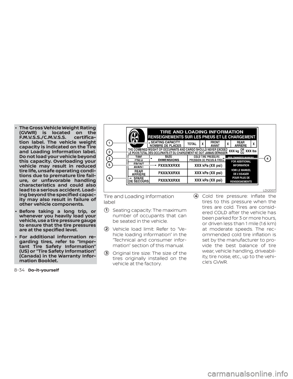
Tire and Loading Information
label
�1Seating capacity: The maximum
number of occupants that can
be seated in the vehicle.
�2Vehicle load limit: Refer to “Ve-
hicle loading information” in the
“Technical and consumer infor-
mation” section of this manual.
�3Original tire size: The size of the
tires originally installed on the
vehicle at the factory.
�4Cold tire pressure: Inflate the
tires to this pressure when the
tires are cold. Tires are consid-
ered COLD af ter the vehicle has
been parked for 3 or more hours,
or driven less than 1 mile (1.6 km)
at moderate speeds. The rec-
ommended cold tire inflation is
set by the manufacturer to pro-
vide the best balance of tire
wear, vehicle handling, driveabil-
ity, tire noise, etc., up to the vehi-
cle’s GVWR.
Page 471 of 516
WARNING
∙ It is extremely dangerous to ride in a cargo area inside a ve-
hicle. In a collision, people riding
in these areas are more likely to
be seriously injured or killed.
∙ Do not allow people to ride in any area of your vehicle that is
not equipped with seats and
seat belts.
∙ Be sure everyone in your vehicle is in a seat and using a seat belt
properly.
TERMS
It is important to familiarize yourself
with the following terms before
loading your vehicle:
∙ Curb Weight (actual weight of your vehicle) - vehicle weight in-
cluding: standard and optional
equipment, fluids, emergency
tools, and spare tire assembly.
This weight does notinclude
passengers and cargo. ∙ GVW (Gross Vehicle Weight) - curb
weight plus the combined weight
of passengers and cargo.
∙ GVWR (Gross Vehicle Weight Rat- ing) - maximum total combined
weight of the unloaded vehicle,
passengers, luggage, hitch, trailer
tongue load and any other op-
tional equipment. This informa-
tion is located on the
F.M.V.S.S./C.M.V.S.S. certification
label.
∙ GAWR (Gross Axle Weight Rating) - maximum weight (load) limit
specified for the front or rear axle.
This information is located on the
F.M.V.S.S./C.M.V.S.S. certification
label.
∙ GCWR (Gross Combined Weight rating) - The maximum total
weight rating of the vehicle, pas-
sengers, cargo, and trailer. ∙ Vehicle Capacity Weight, Load
limit, Total load capacity - maxi-
mum total weight limit specified
of the load (passengers and
cargo) for the vehicle. This is the
maximum combined weight of
occupants and cargo that can be
loaded into the vehicle. If the ve-
hicle is used to tow a trailer, the
trailer tongue weight must be in-
cluded as part of the cargo load.
This information is located on the
Tire and Loading Information la-
bel.
∙ Cargo capacity - permissible weight of cargo, the subtracted
weight of occupants from the
load limit.
VEHICLE LOADING INFORMATION
Technical and consumer information10-19
Page 473 of 516
Steps for determining correct
load limit
1. Locate the statement “The com-bined weight of occupants and
cargo should never exceed XXX
lbs. or XXX kg” on your vehicle’s
placard.
2. Determine the combined weight of the driver and passengers
that will be riding in your vehicle.
3. Subtract the combined weight of the driver and passengers
from XXX lbs. or XXX kg.
4. The resulting figure equals the available amount of cargo and
luggage load capacity. For ex-
ample, if the XXX amount equals
1,400 lbs. and there will be five
150 lbs. passengers in your ve-
hicle, the amount of available
cargo and luggage load capac-
ity is 650 lbs. (1,400-750 (5 X 150) =
650 lbs.) or (640-340 (5 X 70) =
300 kg.) 5. Determine the combined weight
of luggage and cargo being
loaded on the vehicle. That
weight may not safely exceed
the available cargo and luggage
load capacity calculated in
step 4.
6. If your vehicle will be towing a trailer, load from your trailer will
be transferred to your vehicle.
Consult this manual to deter-
mine how this reduces the avail-
able cargo and luggage load ca-
pacity of your vehicle.
Before driving a loaded vehicle, con-
firm that you do not exceed the
GVWR or the GAWR for your vehicle.
For additional information, refer to
“Measurement of weights” in this
section.
Also check tires for proper inflation
pressures. For additional informa-
tion, refer to the “Tire and Loading
Information label” in the “Do-it-
yourself ” section of this manual.
SECURING THE LOAD
For your convenience, tie down hooks (if so
equipped) are placed at each corner of the
truck box. These may be used to help se-
cure cargo loaded into the truck box.
Page 481 of 516
The total cargo load should not exceed the
truck’s pay load weight rating and the
camper’s center of gravity should fall within
the truck’s recommended center of gravity
location when installed.