Page 149 of 516

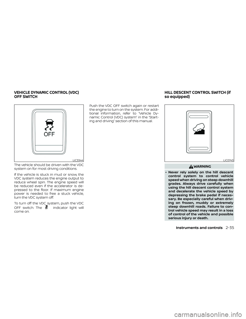
The vehicle should be driven with the VDC
system on for most driving conditions.
If the vehicle is stuck in mud or snow, the
VDC system reduces the engine output to
reduce wheel spin. The engine speed will
be reduced even if the accelerator is de-
pressed to the floor. If maximum engine
power is needed to free a stuck vehicle,
turn the VDC system off.
To turn off the VDC system, push the VDC
OFF switch. The
indicator light will
come on. Push the VDC OFF switch again or restart
the engine to turn on the system. For addi-
tional information, refer to “Vehicle Dy-
namic Control (VDC) system” in the “Start-
ing and driving” section of this manual.
WARNING
∙ Never rely solely on the hill descent
control system to control vehicle
speed when driving on steep downhill
grades. Always drive carefully when
using the hill descent control system
and decelerate the vehicle speed by
depressing the brake pedal if neces-
sary. Be especially careful when driv-
ing on frozen, muddy or extremely
steep downhill roads. Failure to con-
trol vehicle speed may result in a loss
of control of the vehicle and possible
serious injury or death.
LIC3344LIC0743
VEHICLE DYNAMIC CONTROL (VDC)
OFF SWITCH HILL DESCENT CONTROL SWITCH (if
so equipped)
Instruments and controls2-35
Page 150 of 516

∙ The hill descent control may not con-trol the vehicle speed on a hill under
all load or road conditions. Always be
prepared to depress the brake pedal
to control vehicle speed. Failure to do
so may result in a collision or serious
personal injury.
CAUTION
When the hill descent control system
operates continuously for a long time,
the temperature of the brake pads may
increase and the hill descent control
system may be temporarily disabled
(the indicator light will blink). If the indi-
cator light does not come on continu-
ously af ter blinking, stop using the
system.
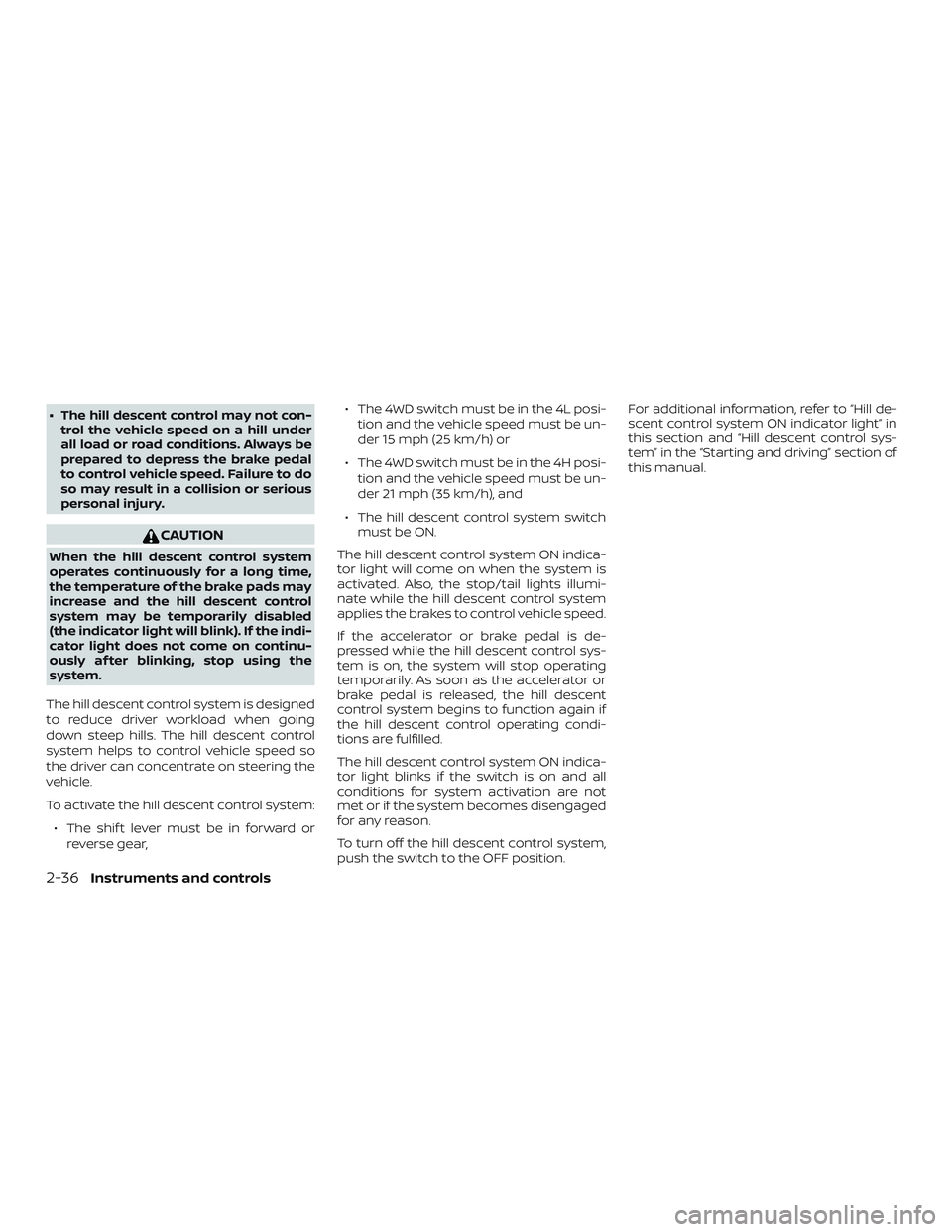
The hill descent control system is designed
to reduce driver workload when going
down steep hills. The hill descent control
system helps to control vehicle speed so
the driver can concentrate on steering the
vehicle.
To activate the hill descent control system: ∙ The shif t lever must be in forward or reverse gear, ∙ The 4WD switch must be in the 4L posi-
tion and the vehicle speed must be un-
der 15 mph (25 km/h) or
∙ The 4WD switch must be in the 4H posi- tion and the vehicle speed must be un-
der 21 mph (35 km/h), and
∙ The hill descent control system switch must be ON.
The hill descent control system ON indica-
tor light will come on when the system is
activated. Also, the stop/tail lights illumi-
nate while the hill descent control system
applies the brakes to control vehicle speed.
If the accelerator or brake pedal is de-
pressed while the hill descent control sys-
tem is on, the system will stop operating
temporarily. As soon as the accelerator or
brake pedal is released, the hill descent
control system begins to function again if
the hill descent control operating condi-
tions are fulfilled.
The hill descent control system ON indica-
tor light blinks if the switch is on and all
conditions for system activation are not
met or if the system becomes disengaged
for any reason.
To turn off the hill descent control system,
push the switch to the OFF position. For additional information, refer to “Hill de-
scent control system ON indicator light” in
this section and “Hill descent control sys-
tem” in the “Starting and driving” section of
this manual.
2-36Instruments and controls
Page 151 of 516

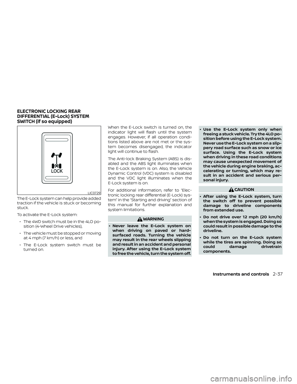
The E-Lock system can help provide added
traction if the vehicle is stuck or becoming
stuck.
To activate the E-Lock system:∙ The 4WD switch must be in the 4LO po- sition (4-Wheel Drive vehicles),
∙ The vehicle must be stopped or moving at 4 mph (7 km/h) or less, and
∙ The E-Lock system switch must be turned on. When the E-Lock switch is turned on, the
indicator light will flash until the system
engages. However, if all operation condi-
tions listed above are not met or the sys-
tem becomes disengaged, the indicator
light will continue to flash.
The Anti-lock Braking System (ABS) is dis-
abled and the ABS light illuminates when
the E-Lock system is on. Also, the Vehicle
Dynamic Control (VDC) system is disabled
and the VDC light illuminates when the
E-Lock system is on.
For additional information, refer to “Elec-
tronic locking rear differential (E-Lock) sys-
tem” in the “Starting and driving” section of
this manual for further explanation and
system limitations.
WARNING
∙ Never leave the E-Lock system on
when driving on paved or hard-
surfaced roads. Turning the vehicle
may result in the rear wheels slipping
and result in an accident and personal
injury. Af ter using the E-Lock system
to free the vehicle, turn the system off. ∙ Use the E-Lock system only when
freeing a stuck vehicle. Try the 4LO po-
sition before using the E-Lock system.
Never use the E-Lock system on a slip-
pery road surface such as snow or ice
surface. Using the E-Lock system
when driving in these road conditions
may cause unexpected movement of
the vehicle during engine braking, ac-
celerating or turning, which may re-
sult in an accident and serious per-
sonal injury.
CAUTION
∙ Af ter using the E-Lock system, turnthe switch off to prevent possible
damage to driveline components
from extended use.
∙ Do not drive over 12 mph (20 km/h) when the system is engaged. Doing so
could result in possible damage to the
driveline.
∙ Do not turn on the E-Lock system while the tires are spinning. Doing so
could damage drivetrain
components.LIC0729
ELECTRONIC LOCKING REAR
DIFFERENTIAL (E-Lock) SYSTEM
SWITCH (if so equipped)
Instruments and controls2-37
Page 152 of 516

WARNING
Pay special attention to your surround-
ings when using the clutch interlock
switch. The vehicle will move forward or
backward according to the gear
selected.
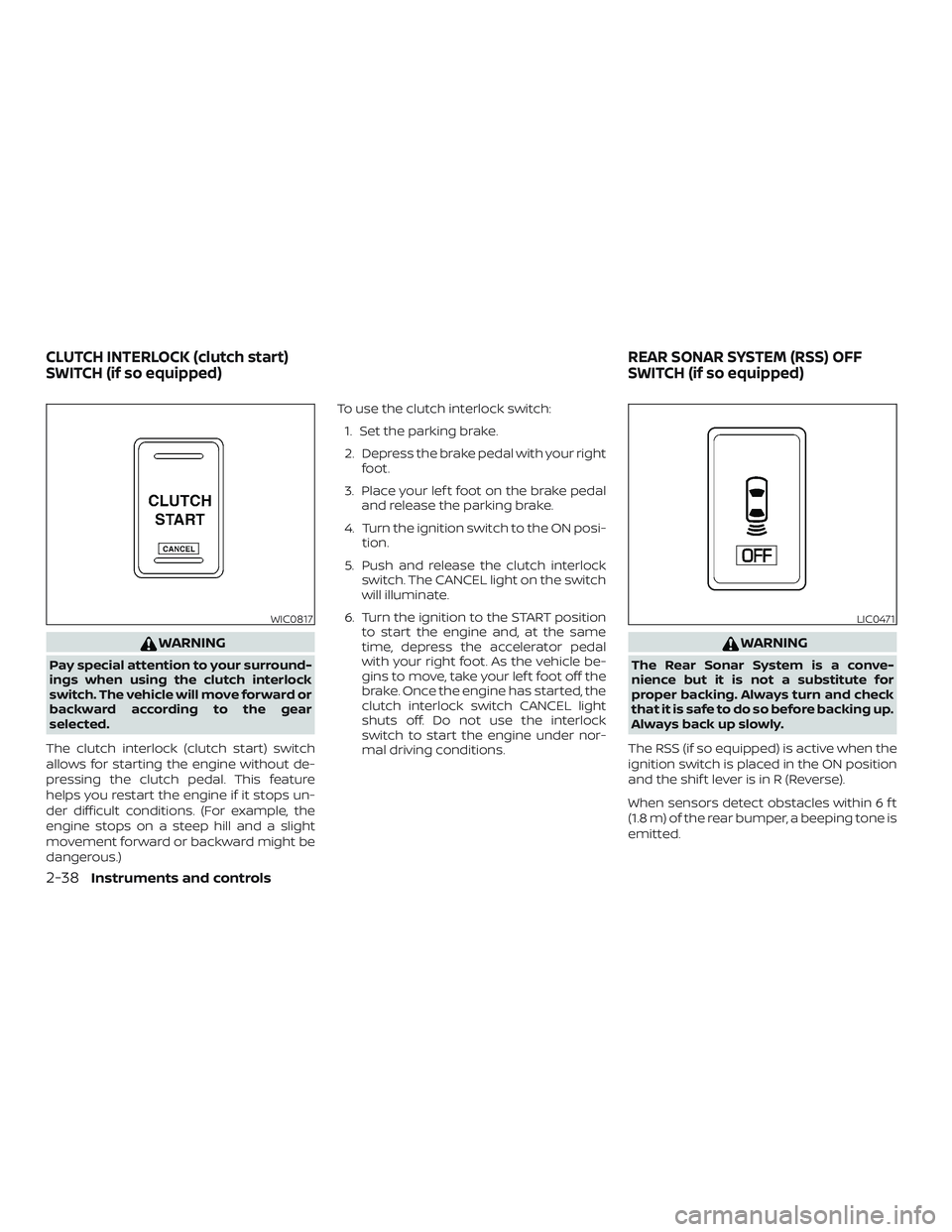
The clutch interlock (clutch start) switch
allows for starting the engine without de-
pressing the clutch pedal. This feature
helps you restart the engine if it stops un-
der difficult conditions. (For example, the
engine stops on a steep hill and a slight
movement forward or backward might be
dangerous.) To use the clutch interlock switch:
1. Set the parking brake.
2. Depress the brake pedal with your right foot.
3. Place your lef t foot on the brake pedal and release the parking brake.
4. Turn the ignition switch to the ON posi- tion.
5. Push and release the clutch interlock switch. The CANCEL light on the switch
will illuminate.
6. Turn the ignition to the START position to start the engine and, at the same
time, depress the accelerator pedal
with your right foot. As the vehicle be-
gins to move, take your lef t foot off the
brake. Once the engine has started, the
clutch interlock switch CANCEL light
shuts off. Do not use the interlock
switch to start the engine under nor-
mal driving conditions.
WARNING
The Rear Sonar System is a conve-
nience but it is not a substitute for
proper backing. Always turn and check
that it is safe to do so before backing up.
Always back up slowly.
The RSS (if so equipped) is active when the
ignition switch is placed in the ON position
and the shif t lever is in R (Reverse).
When sensors detect obstacles within 6 f t
(1.8 m) of the rear bumper, a beeping tone is
emitted.
WIC0817LIC0471
CLUTCH INTERLOCK (clutch start)
SWITCH (if so equipped) REAR SONAR SYSTEM (RSS) OFF
SWITCH (if so equipped)
2-38Instruments and controls
Page 153 of 516

The RSS can be disabled by pushing the
OFF switch. When the system is disabled,
the indicator light on the switch will illumi-
nate.
The system will automatically reset the
next time the ignition switch is placed in
the ON position.
For additional information, refer to “Rear
Sonar System (RSS)” in the “Starting and
driving” section in this manual.The power outlets are for powering electri-
cal accessories such as cellular tele-
phones. They are rated at 12 volt, 120W (10A)
maximum.
The power outlets are powered only when
the ignition switch is in the ACC or ON po-
sition.
Open the cap to use a power outlet.
CAUTION
∙ The outlet and plug may be hot duringor immediately af ter use.
∙ Only certain power outlets are de- signed for use with a cigarette lighter
unit. Do not use any other power out-
let for an accessory lighter. It is rec-
ommended that you visit a NISSAN
dealer for additional information.
∙ Do not use with accessories that ex- ceed a 12 volt, 120W (10A) power draw.
Front row
WIC1420
Center console
LIC0761
POWER OUTLETS
Instruments and controls2-39
Page 154 of 516
∙ Do not use double adapters or morethan one electrical accessory.
∙ Use power outlets with the engine running to avoid discharging the ve-
hicle battery.
∙ Avoid using power outlets when the air conditioner, headlights or rear win-
dow defroster is on.
∙ Before inserting or disconnecting a plug, be sure the electrical accessory
being used is turned off.
∙ Push the plug in as far as it will go. If good contact is not made, the plug
may overheat or the internal tem-
perature fuse may open.
∙ When not in use, be sure to close the cap. Do not allow water or any other
liquids to contact the outlet.
FRONT-DOOR POCKETS REAR-DOOR POCKETS
WIC0824Type A (if so equipped)
LIC0826
STORAGE
2-40Instruments and controls
Page 159 of 516
CONSOLE BOX
Pull up on the lever�1to open the console
box lid
�2.
OVERHEAD SUNGLASSES
STORAGE
To open the sunglasses holder, push and
release.
Only store one pair of sunglasses in the
holder.
WARNING
Keep the sunglasses holder closed
while driving to avoid obstructing the
driver’s view and to help prevent an
accident.
CAUTION
∙ Do not use for anything other than sunglasses.
∙ Do not leave sunglasses in the sun- glasses holder while parking in direct
sunlight. The heat may damage the
sunglasses.
LIC0766LIC3387
Instruments and controls2-45
Page 168 of 516

The interior lights have a three-position
switch and operate regardless of ignition
switch position.
When the switch is in the ON position
�1,
the interior lights illuminate, regardless of
door position. The lights will go off af ter a
period of time unless the ignition switch is
in the ON position.
When the switch is in the O (DOOR) position
�2, the interior lights will stay on for a period
of time when: ∙ The doors are unlocked by the key fob, a
key or the power door lock switch while
all doors are closed and the ignition
switch is in the OFF position.
∙ The driver’s door is opened and then closed while the key is removed from
the ignition switch.
∙ The key is removed from the ignition switch while all doors are closed.
The lights will turn off while the timer is
activated when: ∙ The driver’s door is locked by the key fob, a key, or the power door lock switch. ∙ The ignition switch is turned on.
The lights will turn off automatically af ter a
period of time while doors are open to pre-
vent the battery from becoming dis-
charged.
When the switch is in the OFF position
�3,
the interior lights do not illuminate, regard-
less of door position.
CAUTION
Do not use for extended periods of time
with the engine stopped. This could re-
sult in a discharged battery.
Type A (if so equipped)
LIC0789
Type B (if so equipped)
LIC0792
Type C (if so equipped)
LIC0630
INTERIOR LIGHTS
2-54Instruments and controls