Page 370 of 516

NOTE:
Inspect the spacer every six years and
replace as necessary. It is recommended
that you visit a NISSAN dealer for this
service.
CAUTION
∙ Be sure to center the spare tire sus-pending plate on the wheel and then
lif t the spare tire.
∙ Failure to use the spacer may allow the chain to get stuck on the wheel
nut holes.
Removing bolt-on wheel caps (if
so equipped)
CAUTION
Do not use your hands to pry off wheel
caps or wheel covers. Doing so could
result in personal injury.
The wheel cap
�1is only attached with the
wheel nuts and is separate from the wheel
�2.
To remove the wheel cap, remove the
wheel nuts af ter the jack is securely sup-
porting the vehicle and the tire clears the
ground. For additional information, refer to “Jacking
up vehicle and removing the damaged tire”
in this section.
Take care not to scratch the wheel cap or
wheel surface.
Jacking up vehicle and removing
the damaged tire
WARNING
∙ Never get under the vehicle while it is
supported only by the jack. If it is nec-
essary to work under the vehicle, sup-
port it with safety stands.
∙ Use only the jack provided with your vehicle to lif t the vehicle. Do not use
the jack provided with your vehicle on
other vehicles. The jack is designed
for lif ting only your vehicle during a
tire change.
∙ Use the correct jack-up points. Never use any other part of the vehicle for
jack support.
∙ Never jack up the vehicle more than necessary.
∙ Never use blocks on or under the jack.
LCE2367
6-8In case of emergency
Page 371 of 516
∙ Do not start or run the engine whilevehicle is on the jack. It may cause the
vehicle to move. This is especially true
for vehicles with limited slip
differentials.
∙ Do not allow passengers to stay in the vehicle while it is on the jack.
∙ Never run the engine with a wheel(s) off the ground. It may cause the ve-
hicle to move.
Always refer to the illustration for the cor-
rect placement and jack-up points for your
specific vehicle model and jack type.
Carefully read the caution label attached
to the jack body and the following in-
structions. 1. Loosen each wheel nut 1 or 2 turns by
turning counterclockwise with the
wheel nut wrench. Do not remove the
wheel nuts until the tire is off the
ground.
WCE0152
In case of emergency6-9
Page 380 of 516
Two-Wheel Drive models with
automatic transmission
NISSAN recommends that your vehicle be
towed with the driving (rear) wheels off the
ground or place the vehicle on a flatbed
truck as illustrated.
CAUTION
∙ Never tow automatic transmissionmodels with the rear wheels on the
ground or four wheels on the ground
(forward or backward), as this may
cause serious and expensive damage
to the transmission. If it is necessary
to tow the vehicle with the front
wheels raised always use towing dol-
lies under the rear wheels.
∙ When towing automatic transmission models with the front wheels on the
ground or on towing dollies: – Place the ignition switch in the OFF
position, and secure the steering
wheel in a straight-ahead position
with a rope or similar device. Never
secure the steering wheel by plac-
ing the ignition switch in the LOCK
position. This may damage the
steering lock mechanism (for
models with a steering lock
mechanism).
LCE2311
6-18In case of emergency
Page 392 of 516

When performing any inspection or main-
tenance work on your vehicle, always take
care to prevent serious accidental injury to
yourself or damage to the vehicle. The fol-
lowing are general precautions which
should be closely observed.
WARNING
∙Park the vehicle on a level surface, ap-
ply the parking brake securely and
block the wheels to prevent the vehicle
from moving. For manual transmission
models, move the shif t lever to N (Neu-
tral). For Automatic Transmission (A/T)
move the shif t lever to P (Park)
∙ Be sure the ignition key is in the OFF orLOCK position when performing any
parts replacement or repairs.
∙ If you must work with the engine run- ning, keep your hands, clothing, hair
and tools away from moving fans,
belts and any other moving parts.
∙ It is advisable to secure or remove any loose clothing and remove any jew-
elry, such as rings, watches, etc. be-
fore working on your vehicle.
∙ Always wear eye protection whenever you work on your vehicle. ∙ If you must run the engine in an en-
closed space such as a garage, be sure
there is proper ventilation for exhaust
gases to escape.
∙ Never get under the vehicle while it is supported only by a jack. If it is neces-
sary to work under the vehicle, sup-
port it with safety stands.
∙ Keep smoking materials, flame and sparks away from the fuel tank and
battery.
∙ On gasoline engine models, the fuel filter or fuel lines should be serviced
because the fuel lines are under high
pressure even when the engine is off.
It is recommended that you visit a
NISSAN dealer for this service.
CAUTION
∙ Do not work under the hood while theengine is hot. Turn the engine off and
wait until it cools down.
∙
Avoid contact with used engine oil and
coolant. Improperly disposed engine
oil, engine coolant and/or other vehicle
fluids can damage the environment. Al-
ways conform to local regulations for
disposal of vehicle fluid.
∙ Never leave the engine or the trans- mission related component harness
connector disconnected while the ig-
nition switch is in the ON position.
∙ Never connect or disconnect the bat- tery or any transistorized component
while the ignition switch is in the ON
position.
This “Do-it-yourself ” section gives instruc-
tions regarding only those items which are
relatively easy for an owner to perform.
A Genuine NISSAN service manual is also
available. For additional information, refer
to “Owner’s Manual/Service Manual order
information” in the “Technical and con-
sumer information” section of this manual.
You should be aware that incomplete or
improper servicing may result in operating
difficulties or excessive emissions, and
could affect warranty coverage. If in doubt
about any servicing, it is recommended
that you have it done by a NISSAN dealer.
MAINTENANCE PRECAUTIONS
8-2Do-it-yourself
Page 400 of 516
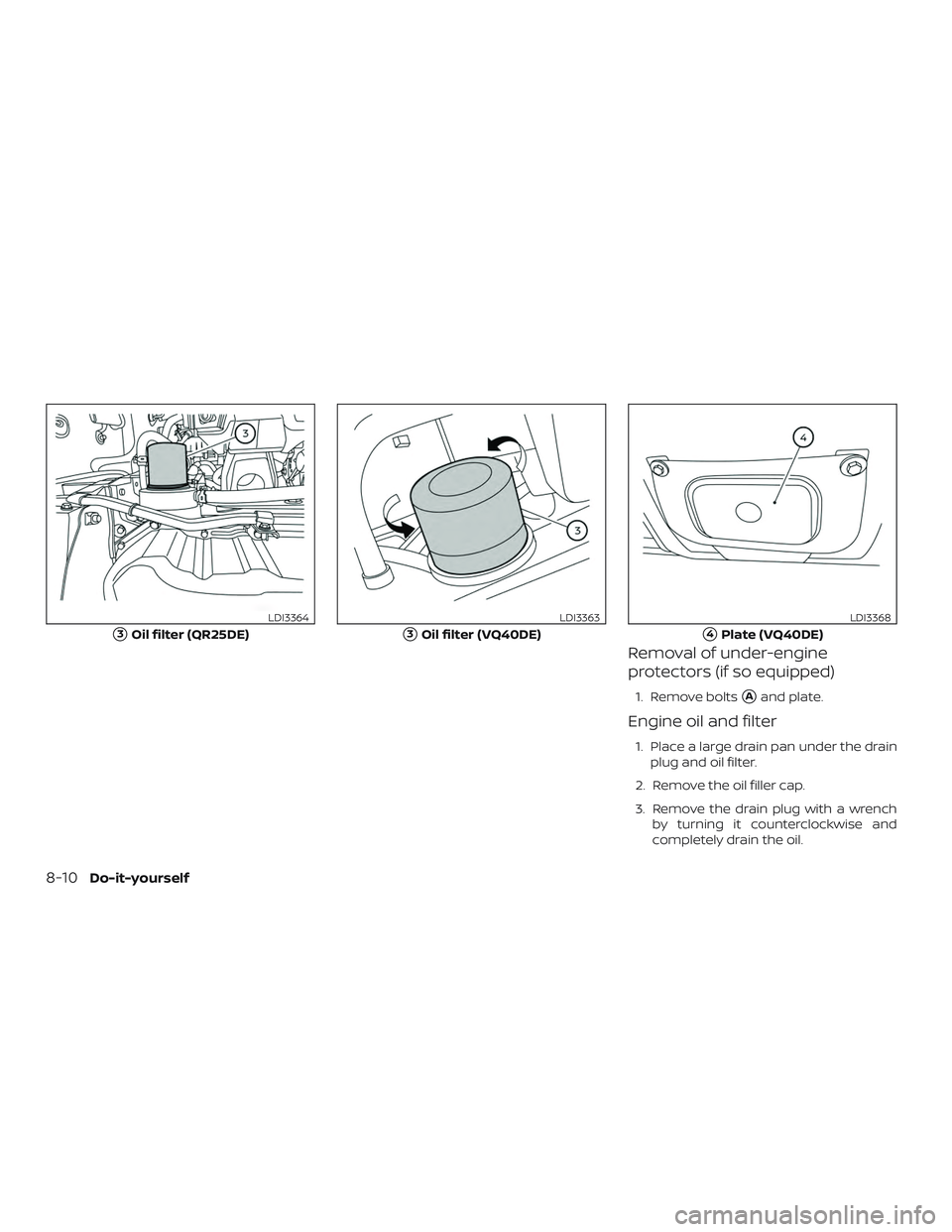
Removal of under-engine
protectors (if so equipped)
1. Remove bolts�Aand plate.
Engine oil and filter
1. Place a large drain pan under the drainplug and oil filter.
2. Remove the oil filler cap.
3. Remove the drain plug with a wrench by turning it counterclockwise and
completely drain the oil.
�3Oil filter (QR25DE)
LDI3364
�3Oil filter (VQ40DE)
LDI3363
�4Plate (VQ40DE)
LDI3368
8-10Do-it-yourself
Page 401 of 516

CAUTION
Be careful not to burn yourself, as the
engine oil is hot.
WARNING
∙Prolonged and repeated contact with
used engine oil may cause skin cancer.
∙ Try to avoid direct skin contact withused oil. If skin contact is made, wash
thoroughly with soap or hand cleaner
as soon as possible.
∙ Keep used engine oil out of reach of children. 4. Loosen the oil filter with an oil filter
wrench by turning it counterclockwise.
Remove the oil filter by turning it by
hand.
5. Wipe the engine oil filter mounting sur- face with a clean rag.
CAUTION
Be sure to remove any old gasket mate-
rial remaining on the sealing surface of
the engine. Failure to do so could lead to
an oil leak and engine damage.
∙ The dipstick must be inserted in placeto prevent oil spillage from the dip-
stick hole when filling the engine with
oil.
6. Coat the gasket on the new filter with clean engine oil.
7. Screw in the oil filter clockwise until a slight resistance is felt, then tighten ad-
ditionally more than 2/3 turn.
Oil filter tightening torque: 11 to 15 f t-lb (14.7 to 20.6 N·m) 8. Clean and re-install the drain plug with
a new washer. Securely tighten the
drain plug with a wrench. Do not use
excessive force.
Drain plug tightening torque: 22 to 29 f t-lb (29 to 39 N·m)
9. Refill the engine with the recom- mended oil through the oil filler open-
ing, and install the oil filler cap securely.
For additional information about drain and
refill capacity, refer to “Recommended
fluids/lubricants and capacities” in the
“Technical and consumer information” sec-
tion of this manual. The drain and refill ca-
pacity depends on the oil temperature and
drain time. Use these specifications for ref-
erence only. Always use the dipstick to de-
termine the proper amount of oil in the
engine.
10. Start the engine and check for leakage around the drain plug and the oil filter.
Correct as required. Turn the engine off
and wait more than 15 minutes. Check
the oil level with the dipstick. Add en-
gine oil if necessary.
LDI3366
Do-it-yourself8-11
Page 407 of 516

CAUTION
∙ Do not ground accessories directly tothe battery terminal. Doing so will by-
pass the variable voltage control sys-
tem and the vehicle battery may not
charge completely.
∙ Use electrical accessories with the en- gine running to avoid discharging the
vehicle battery.
Your vehicle is equipped with a variable
voltage control system. This system mea-
sures the amount of electrical discharge
from the battery and controls voltage gen-
erated by the generator. The current sensor
�Ais located near the
battery along the negative battery cable. If
you add electrical accessories to your ve-
hicle, be sure to ground them to a suitable
body ground such as the frame or engine
block area.
1. Power steering fluid pump pulley
2. Automatic belt tensioner pulley
3. Cooling fan pulley
4. Air conditioner compressor pulley
5. Crankshaf t pulley
6. Generator pulley
WARNING
Be sure the ignition key is in the OFF or
LOCK position before servicing drive
belt. The engine could rotate
unexpectedly.
1. Visually inspect the belt for signs of un- usual wear, cuts, fraying or looseness. If
LDI3300VQ40DE
WDI0639
VARIABLE VOLTAGE CONTROL
SYSTEM DRIVE BELT
Do-it-yourself8-17
Page 414 of 516

ENGINE COMPARTMENT
WARNING
Never use a fuse of a higher or lower
amperage rating than that specified on
the fuse box cover. This could damage
the electrical system or electronic con-
trol units or cause a fire.If any electrical equipment does not come
on, check for an open fuse.
1. Be sure the ignition switch and the headlight switch are OFF.
2. Open the engine hood.
3. Remove the fuse box cover by pushing the tab and lif ting the cover up.
4. Remove the fuse with the fuse puller. The fuse puller is located in the center
of the fuse block in the passenger
compartment.
5. If the fuse is open
�A, replace it with a
new fuse
�B.
6. If a new fuse also opens, have the elec- trical system checked and repaired. It is
recommended that you visit a NISSAN
dealer for this service.
Fusible links
If the electrical equipment does not oper-
ate and fuses are in good condition, check
the fusible links. If any of these fusible links
are melted, replace with only Genuine
NISSAN parts.
LDI2838LDI2826
8-24Do-it-yourself

 wheels off the
ground or place the vehicle on a flatbed
truck as illustrated.
CA")