2019 NISSAN ARMADA engine
[x] Cancel search: enginePage 146 of 536
2-52Instruments and controls
CAUTION
.Use power outlet with the engine
running to avoid discharging the
vehicle battery.
. Avoid using power outlet when
the air conditioner, headlights or
rear window defroster is on.
. Before inserting or disconnecting
a plug, be sure the electrical
accessory being used is turned
OFF.
. When not in use, be sure to close
the cap. Do not allow water or any
liquid to contact the outlet.
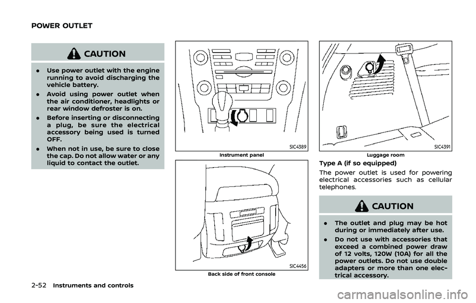
SIC4389
Instrument panel
SIC4456Back side of front console
SIC4391
Luggage room
Type A (if so equipped)
The power outlet is used for powering
electrical accessories such as cellular
telephones.
CAUTION
.The outlet and plug may be hot
during or immediately after use.
. Do not use with accessories that
exceed a combined power draw
of 12 volts, 120W (10A) for all the
power outlets. Do not use double
adapters or more than one elec-
trical accessory.
POWER OUTLET
Page 147 of 536
.This power outlet is not designed
for use with a cigarette lighter
unit.
. Push the plug in as far as it will
go. If good contact is not made,
the plug may overheat or the
internal temperature fuse may
blow.
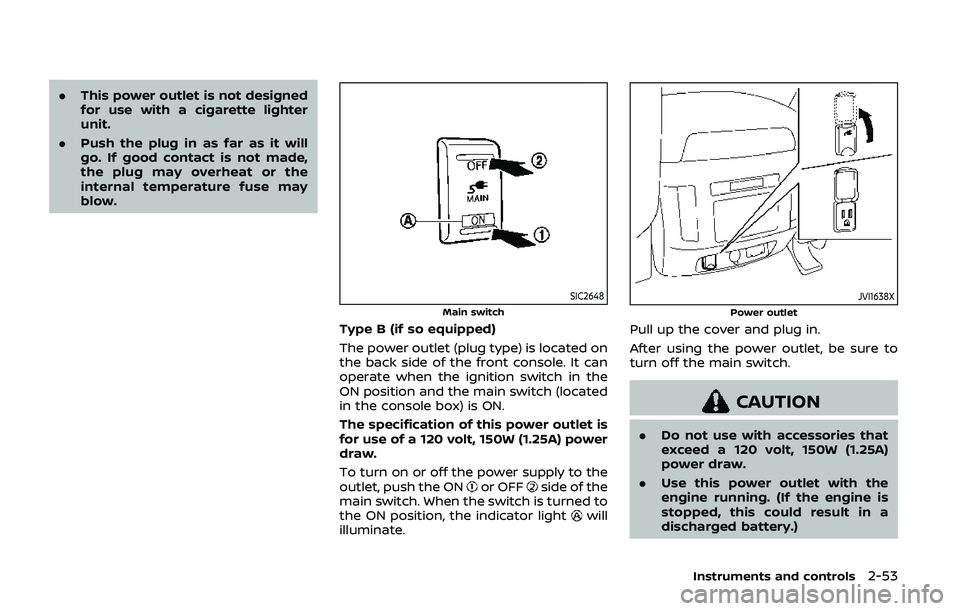
SIC2648
Main switch
Type B (if so equipped)
The power outlet (plug type) is located on
the back side of the front console. It can
operate when the ignition switch in the
ON position and the main switch (located
in the console box) is ON.
The specification of this power outlet is
for use of a 120 volt, 150W (1.25A) power
draw.
To turn on or off the power supply to the
outlet, push the ON
or OFFside of the
main switch. When the switch is turned to
the ON position, the indicator light
will
illuminate.
JVI1638X
Power outlet
Pull up the cover and plug in.
After using the power outlet, be sure to
turn off the main switch.
CAUTION
. Do not use with accessories that
exceed a 120 volt, 150W (1.25A)
power draw.
. Use this power outlet with the
engine running. (If the engine is
stopped, this could result in a
discharged battery.)
Instruments and controls2-53
Page 157 of 536
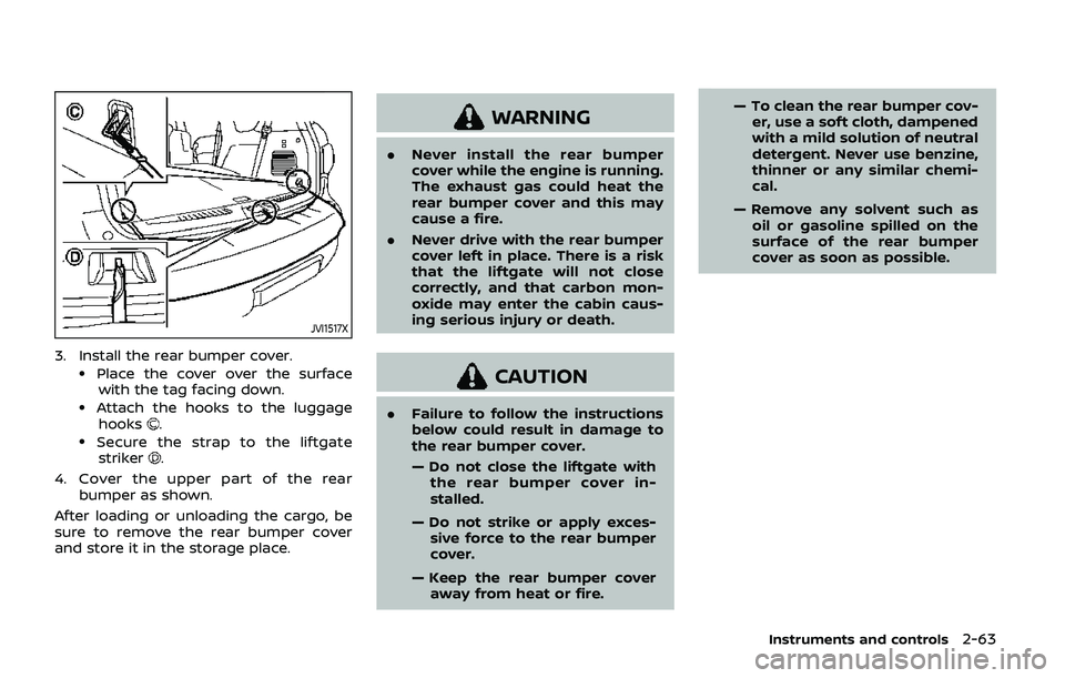
JVI1517X
3. Install the rear bumper cover..Place the cover over the surfacewith the tag facing down.
.Attach the hooks to the luggage
hooks..Secure the strap to the liftgatestriker.
4. Cover the upper part of the rear bumper as shown.
After loading or unloading the cargo, be
sure to remove the rear bumper cover
and store it in the storage place.
WARNING
. Never install the rear bumper
cover while the engine is running.
The exhaust gas could heat the
rear bumper cover and this may
cause a fire.
. Never drive with the rear bumper
cover left in place. There is a risk
that the liftgate will not close
correctly, and that carbon mon-
oxide may enter the cabin caus-
ing serious injury or death.
CAUTION
.Failure to follow the instructions
below could result in damage to
the rear bumper cover.
— Do not close the liftgate with
the rear bumper cover in-
stalled.
— Do not strike or apply exces- sive force to the rear bumper
cover.
— Keep the rear bumper cover away from heat or fire. — To clean the rear bumper cov-
er, use a soft cloth, dampened
with a mild solution of neutral
detergent. Never use benzine,
thinner or any similar chemi-
cal.
— Remove any solvent such as oil or gasoline spilled on the
surface of the rear bumper
cover as soon as possible.
Instruments and controls2-63
Page 160 of 536
2-66Instruments and controls
Auto reverse function
WARNING
There are some small distances im-
mediately before the closed position
which cannot be detected. Make sure
that all passengers have their hands,
etc., inside the vehicle before closing
the window.
If the control unit detects something
caught in the window as it is closing, the
window will be immediately lowered.
The auto reverse function can be acti-
vated when the window is closed by
automatic operation when the ignition
switch is in the ON position or for 45
seconds after the ignition switch is
pushed to the OFF position.
Depending on the environment or driv-
ing conditions, the auto reverse func-
tion may be activated if an impact or
load similar to something being caught
in the window occurs.
If the windows do not close auto-
matically
If the power window automatic function
(closing only) does not operate properly,
perform the following procedure to initi-
alize the power window system.
1. Push the ignition switch to start the engine.
2. Close the door.
3. After starting the engine, open the window completely by operating the
power window switch.
4. Pull the power window switch and hold it to close the window, and then
hold the switch more than 3 seconds
after the window is closed completely.
5. Release the power window switch. Operate the window by the automatic
function to confirm the initialization is
complete.
6. Perform steps 2 through 5 above for other windows.
If the power window automatic function
does not operate properly after perform-
ing the procedure above, have your
vehicle checked. It is recommended you
visit a NISSAN dealer for this service.
WARNING
. In an accident you could be
thrown from the vehicle through
an open moonroof. Always use
seat belts and child restraints.
. Do not allow anyone to stand up
or extend any portion of their
body out of the moonroof open-
ing while the vehicle is in motion
or while the moonroof is closing.
CAUTION
.Remove water drops, snow, ice or
sand from the moonroof before
opening.
. Do not place any heavy object on
the moonroof or surrounding
area.
POWER MOONROOF
The moonroof only operates when the
ignition switch is in the ON position.
The moonroof is operational for about 45
seconds, even if the ignition switch is
pushed to the OFF position. If the driver’s
door or the passenger’s door is opened
MOONROOF (if so equipped)
Page 163 of 536
CAUTION
.Turn off the lights when you leave
the vehicle.
. Do not use the lights for extended
periods of time with the engine
stopped. This could result in a
discharged battery.
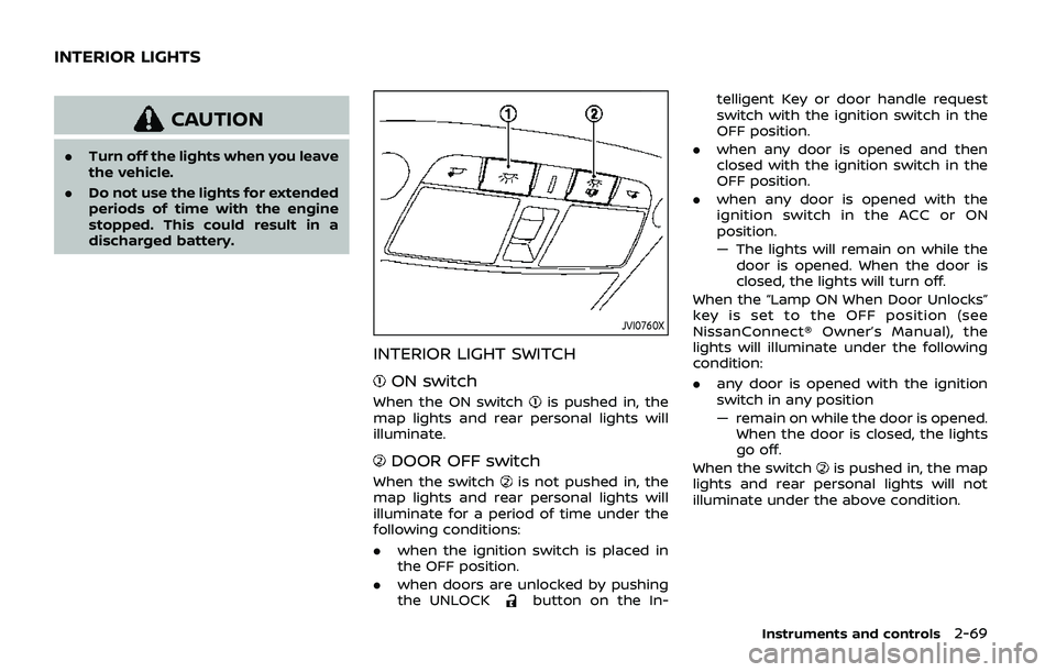
JVI0760X
INTERIOR LIGHT SWITCH
ON switch
When the ON switchis pushed in, the
map lights and rear personal lights will
illuminate.
DOOR OFF switch
When the switchis not pushed in, the
map lights and rear personal lights will
illuminate for a period of time under the
following conditions:
. when the ignition switch is placed in
the OFF position.
. when doors are unlocked by pushing
the UNLOCK
button on the In- telligent Key or door handle request
switch with the ignition switch in the
OFF position.
. when any door is opened and then
closed with the ignition switch in the
OFF position.
. when any door is opened with the
ignition switch in the ACC or ON
position.
— The lights will remain on while the
door is opened. When the door is
closed, the lights will turn off.
When the “Lamp ON When Door Unlocks”
key is set to the OFF position (see
NissanConnect® Owner’s Manual), the
lights will illuminate under the following
condition:
. any door is opened with the ignition
switch in any position
— remain on while the door is opened.
When the door is closed, the lights
go off.
When the switch
is pushed in, the map
lights and rear personal lights will not
illuminate under the above condition.
Instruments and controls2-69
INTERIOR LIGHTS
Page 166 of 536

2-72Instruments and controls
stop and reverse features as re-
quired by federal safety stan-
dards. (These standards became
effective for opener models man-
ufactured after April 1, 1982). A
garage door opener which cannot
detect an object in the path of a
closing garage door and then
automatically stop and reverse,
does not meet current federal
safety standards. Using a garage
door opener without these fea-
tures increases the risk of serious
injury or death.
. During the programming proce-
dure your garage door or security
gate will open and close (if the
transmitter is within range). Make
sure that people or objects are
clear of the garage door, gate,
etc. that you are programming.
. Your vehicle’s engine should be
turned off while programming
the HomeLink® Universal Trans-
ceiver. Do not breathe exhaust
gases; they contain colorless
and odorless carbon monoxide.
Carbon monoxide is dangerous. It
can cause unconsciousness or
death.PROGRAMMING HomeLink®
The following steps show generic instruc-
tions how to program a HomeLink®
button. If you have any questions or are
having difficulty programming your
HomeLink® buttons, refer to the
HomeLink® web site at: www.homelink.
com/nissan or call 1-800-355-3515.
NOTE:
It is also recommended that a new
battery be placed in the hand-held
transmitter of the device being pro-
grammed to HomeLink® for quicker
programming and accurate transmis-
sion of the radio-frequency.
1. Position the end of your hand-held
transmitter 1-3 in (26-76 mm) away
from the HomeLink® surface, keeping
the HomeLink® indicator light
in
view.
JVI0428X
2. Using both hands, simultaneously
press and hold the desired HomeLink®
button and handheld transmitter but-
ton. DO NOT release until the
HomeLink® indicator light
flashes
slowly and then rapidly. When the
indicator light flashes rapidly, both
buttons may be released. (The rapid
flashing indicates successful pro-
gramming.)
NOTE:
Some devices to be programmed
may require you to replace Step 2
with the cycling procedure noted in
the “Programming HomeLink® for
Canadian customers and gate open-
ers” (P.2-73).
Page 170 of 536

2-76Instruments and controls
stop and reverse features as re-
quired by federal safety stan-
dards. (These standards became
effective for opener models man-
ufactured after April 1, 1982). A
garage door opener which cannot
detect an object in the path of a
closing garage door and then
automatically stop and reverse,
does not meet current federal
safety standards. Using a garage
door opener without these fea-
tures increases the risk of serious
injury or death.
. During the programming proce-
dure your garage door or security
gate will open and close (if the
transmitter is within range). Make
sure that people or objects are
clear of the garage door, gate,
etc. that you are programming.
. Your vehicle’s engine should be
turned off while programming
the HomeLink® Universal Trans-
ceiver. Do not breathe exhaust
gases; they contain colorless
and odorless carbon monoxide.
Carbon monoxide is dangerous. It
can cause unconsciousness or
death.PROGRAMMING HomeLink®
The following steps show generic instruc-
tions how to program a HomeLink®
button. If you have any questions or are
having difficulty programming your
HomeLink® buttons, refer to the
HomeLink® web site at: www.homelink.
com/nissan or call 1-800-355-3515.
NOTE:
It is also recommended that a new
battery be placed in the hand-held
transmitter of the device being pro-
grammed to HomeLink® for quicker
programming and accurate transmis-
sion of the radio-frequency.
JVI1689X
HomeLink® buttons (1-3)Indicator light (appears above each
HomeLink® button)
Status display (where the current condi-
tion of the HomeLink® is displayed)
Page 175 of 536
3 Pre-driving checks and adjustments
Keys ........................................................................\
................................. 3-2Intelligent Key ........................................................................\
... 3-2
Valet hand-off ........................................................................\
... 3-4
Doors ........................................................................\
.............................. 3-4 Locking with mechanical key ...................................... 3-4
Opening and closing windows with the
mechanical key ........................................................................\
3-5
Locking with inside lock knob ..................................... 3-5
Locking with power door lock switch ................... 3-5
Automatic door locks ......................................................... 3-6
Child safety rear door lock ........................................... 3-6
Intelligent Key system .............................................................. 3-7 Intelligent Key operating range ................................. 3-9
Door locks/unlocks precaution .................................. 3-9
Intelligent Key operation .............................................. 3-10
Battery saver system ....................................................... 3-12
Warning signals .................................................................... 3-12
Troubleshooting guide ................................................... 3-13
Remote keyless entry system ......................................... 3-15 How to use remote keyless entry system ...... 3-16
Remote engine start (if so equipped) ....................... 3-19 Remote engine start operating range ............... 3-19
Remote starting the engine ....................................... 3-19
Extending engine run time ......................................... 3-20 Canceling a remote engine start ........................ 3-20
Conditions the remote engine start will
not work ........................................................................\
.......... 3-20
Hood ........................................................................\
............................ 3-21
Liftgate ........................................................................\
...................... 3-22 Operating manual liftgate ......................................... 3-22
Operating power liftgate (if so equipped) ...... 3-22
Auto closure ........................................................................\
3-25
Liftgate release lever ..................................................... 3-26
Fuel-filler door ........................................................................\
..... 3-26
Opening the fuel-filler door ...................................... 3-26
Fuel-filler cap ....................................................................... 3-27
Tilt/telescopic steering ........................................................ 3-29
Electric operation ............................................................. 3-30
Sun visors ........................................................................\
................ 3-30
Mirrors ........................................................................\
........................ 3-31
Inside mirror ........................................................................\
. 3-31
Outside mirrors .................................................................. 3-38
Vanity mirror ........................................................................\
3-40
Automatic drive positioner (if so equipped) ........ 3-40
Entry/exit function .......................................................... 3-40
Memory storage ................................................................ 3-41
Setting memory function ........................................... 3-42
System operation ............................................................. 3-42