2019 NISSAN ARMADA check engine light
[x] Cancel search: check engine lightPage 369 of 536

Condition B
Under the following conditions, making it
impossible to detect a vehicle ahead, the
AEB system is automatically turned off.
The AEB system warning light (orange)
will illuminate and the “FRONT RADAR
OBSTRUCTION” warning message will ap-
pear in the vehicle information display.
.When the sensor area of the front
bumper is covered with dirt or is
obstructed
Action to take:
If the AEB system warning light (orange)
comes on, stop the vehicle in a safe
place, place the shift lever in the P (Park)
position and turn the engine off. Clean
the radar cover below the front bumper
with a soft cloth, and restart the engine. If
the AEB system warning light continues
to illuminate, have the AEB system
checked. It is recommended you visit a
NISSAN dealer for this service.
. When driving on roads with limited
road structures or buildings (for ex-
ample, long bridges, deserts, snow
fields, driving next to long walls)
Action to take:
When the above conditions no longer
exist, the AEB system will resume auto-
matically.
Condition C
When the accelerator pedal actuator
detects that the internal motor tempera-
ture is high, the AEB system is automati-
cally turned off. The AEB system warning
light (orange)
will illuminate.
Action to take:
When the above conditions no longer
exist, the AEB system will resume auto-
matically.
Condition D
When VDC system is OFF, the AEB brake
will not operate. In this case only visible
and audible warning operates. The AEB
system warning light (orange) will illumi-
nate.
Action to take:
When the above conditions no longer
exist, the AEB system will resume auto-
matically.
SYSTEM MALFUNCTION
If the AEB system malfunctions, it will be
turned off automatically, a chime will
sound, the AEB system warning light
(orange)
will illuminate. Action to take:
If the warning light (orange)
comes on,
stop the vehicle in a safe location and
place the shift lever in the P (Park)
position. Turn the engine off and restart
the engine. If the warning light continues
to illuminate, have the AEB system
checked. It is recommended you visit a
NISSAN dealer for this service.
Starting and driving5-109
Page 378 of 536

5-118Starting and driving
JVS0675X
SYSTEM TEMPORARILY UNAVAIL-
ABLE
Condition A
When the radar sensor picks up interfer-
ence from another radar source, making
it impossible to detect a vehicle ahead,
the I-FCW system is automatically turned
off. The AEB system warning light (or-
ange)
will illuminate.
Action to take:
When the above conditions no longer
exist, the I-FCW system will resume auto-
matically.
Condition B
Under the following conditions, making it
impossible to detect a vehicle ahead, the
I-FCW system is automatically turned off.
The AEB system warning light (orange)
will illuminate and the “FRONT RADAR
OBSTRUCTION” warning message will ap-
pear in the vehicle information display.
. When the sensor area of the front
bumper is covered with dirt or is
obstructed
Action to take:
If the AEB system warning light (orange)
comes on, stop the vehicle in a safe
place, place the shift lever in the P (Park)
position and turn the engine off. Clean
the radar cover below the front bumper
with a soft cloth, and restart the engine. If
the warning light continues to illuminate,
have the I-FCW system checked. It is
recommended you visit a NISSAN dealer
for this service.
. When driving on roads with limited
road structures or buildings (for ex-
ample, long bridges, deserts, snow
fields, driving next to long walls)
Action to take:
When the above conditions no longer
exist, the I-FCW system will resume auto-
matically.
SYSTEM MALFUNCTION
If the I-FCW system malfunctions, it will be
turned off automatically, a chime will
sound, the AEB system warning light
(orange)
will illuminate.
Action to take:
If the warning light (orange)
illuminates,
stop the vehicle in a safe location and
place the shift lever in the P (Park)
position. Turn the engine off and restart
the engine. If the warning light continues
to illuminate, have the I-FCW system
checked. It is recommended you visit a
NISSAN dealer for this service.
Page 392 of 536

5-132Starting and driving
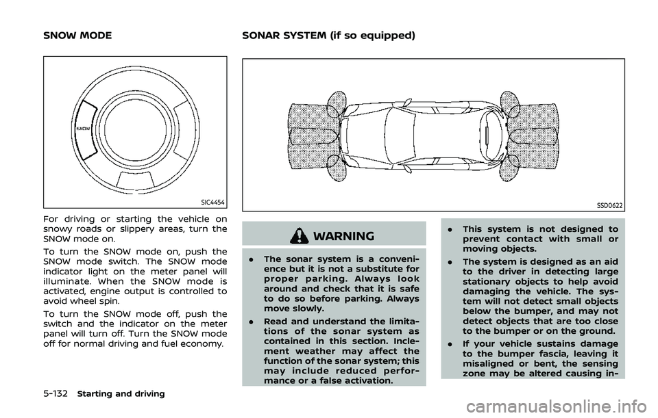
SIC4454
For driving or starting the vehicle on
snowy roads or slippery areas, turn the
SNOW mode on.
To turn the SNOW mode on, push the
SNOW mode switch. The SNOW mode
indicator light on the meter panel will
illuminate. When the SNOW mode is
activated, engine output is controlled to
avoid wheel spin.
To turn the SNOW mode off, push the
switch and the indicator on the meter
panel will turn off. Turn the SNOW mode
off for normal driving and fuel economy.
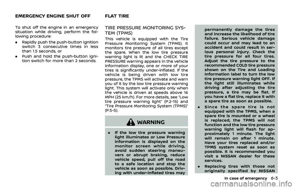
SSD0622
WARNING
.The sonar system is a conveni-
ence but it is not a substitute for
proper parking. Always look
around and check that it is safe
to do so before parking. Always
move slowly.
. Read and understand the limita-
tions of the sonar system as
contained in this section. Incle-
ment weather may affect the
function of the sonar system; this
may include reduced perfor-
mance or a false activation. .
This system is not designed to
prevent contact with small or
moving objects.
. The system is designed as an aid
to the driver in detecting large
stationary objects to help avoid
damaging the vehicle. The sys-
tem will not detect small objects
below the bumper, and may not
detect objects that are too close
to the bumper or on the ground.
. If your vehicle sustains damage
to the bumper fascia, leaving it
misaligned or bent, the sensing
zone may be altered causing in-
SNOW MODE SONAR SYSTEM (if so equipped)
Page 397 of 536

faces even with ABS. Stopping
distances may also be longer on
rough, gravel or snow covered
roads, or if you are using tire
chains. Always maintain a safe
distance from the vehicle in front
of you. Ultimately, the driver is
responsible for safety.
. Tire type and condition may also
affect braking effectiveness.
— When replacing tires, install
the specified size of tires on
all four wheels.
— When installing a spare tire, make sure that it is the proper
size and type as specified on
the Tire and Loading Informa-
tion label. See “Tire and load-
ing information label” (P.10-
12).
— For detailed information, see “Wheels and tires” (P.8-30).
The Anti-lock Braking System (ABS) con-
trols the brakes so the wheels do not lock
during hard braking or when braking on
slippery surfaces. The system detects the
rotation speed at each wheel and varies
the brake fluid pressure to prevent each
wheel from locking and sliding. By pre-
venting each wheel from locking, the system helps the driver maintain steering
control and helps to minimize swerving
and spinning on slippery surfaces.
Using the system
Depress the brake pedal and hold it down.
Depress the brake pedal with firm steady
pressure, but do not pump the brakes.
The ABS will operate to prevent the
wheels from locking up. Steer the vehicle
to avoid obstacles.
WARNING
Do not pump the brake pedal. Doing
so may result in increased stopping
distances.
Self-test feature
The ABS includes electronic sensors, elec-
tric pumps, hydraulic solenoids and a
computer. The computer has a built-in
diagnostic feature that tests the system
each time you start the engine and move
the vehicle at a low speed in forward or
reverse. When the self-test occurs, you
may hear a “clunk” noise and/or feel a
pulsation in the brake pedal. This is
normal and does not indicate a malfunc-
tion. If the computer senses a malfunc-
tion, it switches the ABS off and
illuminates the ABS warning light on the
instrument panel. The brake system then
operates normally, but without anti-lock
assistance.
If the ABS warning light illuminates during
the self-test or while driving, have the
vehicle checked. It is recommended you
visit a NISSAN dealer for this service.
Normal operation
The ABS operates at speeds above 3 to 6
MPH (5 to 10 km/h). The speed varies
according to road conditions.
When the ABS senses that one or more
wheels are close to locking up, the
actuator rapidly applies and releases
hydraulic pressure. This action is similar
to pumping the brakes very quickly. You
may feel a pulsation in the brake pedal
and hear a noise from under the hood or
feel a vibration from the actuator when it
is operating. This is normal and indicates
that the ABS is operating properly. How-
ever, the pulsation may indicate that road
conditions are hazardous and extra care
is required while driving.
Starting and driving5-137
Page 405 of 536

To shut off the engine in an emergency
situation while driving, perform the fol-
lowing procedure:
.Rapidly push the push-button ignition
switch 3 consecutive times in less
than 1.5 seconds, or
. Push and hold the push-button igni-
tion switch for more than 2 seconds.TIRE PRESSURE MONITORING SYS-
TEM (TPMS)
This vehicle is equipped with the Tire
Pressure Monitoring System (TPMS). It
monitors tire pressure of all tires except
the spare. When the low tire pressure
warning light is lit and the CHECK TIRE
PRESSURE warning appears in the vehicle
information display, one or more of your
tires is significantly under-inflated. If the
vehicle is being driven with low tire
pressure, the TPMS will activate and warn
you of it by the low tire pressure warning
light. This system will activate only when
the vehicle is driven at speeds above 16
MPH (25 km/h). For more details, see “Low
tire pressure warning light” (P.2-15) and
“Tire Pressure Monitoring System (TPMS)”
(P.5-5).
WARNING
.If the low tire pressure warning
light illuminates or Low Pressure
information is displayed on the
monitor screen while driving,
avoid sudden steering maneu-
vers or abrupt braking, reduce
vehicle speed, pull off the road
to a safe location and stop the
vehicle as soon as possible. Driv-
ing with under-inflated tires may permanently damage the tires
and increase the likelihood of tire
failure. Serious vehicle damage
could occur and may lead to an
accident and could result in ser-
ious personal injury. Check the
tire pressure for all four tires.
Adjust the tire pressure to the
recommended COLD tire pressure
shown on the Tire and Loading
Information label to turn the low
tire pressure warning light OFF. If
the light still illuminates while
driving after adjusting the tire
pressure, a tire may be flat. If
you have a flat tire, replace it with
a spare tire as soon as possible.
. Since the spare tire is not
equipped with the TPMS, when a
spare tire is mounted or a wheel
is replaced, the TPMS will not
function and the low tire pressure
warning light will flash for ap-
proximately 1 minute. The light
will remain on after 1 minute.
Have your tires replaced and/or
TPMS system reset as soon as
possible. It is recommended you
visit a NISSAN dealer for these
services.
. Replacing tires with those not
originally specified by NISSAN
In case of emergency6-3
EMERGENCY ENGINE SHUT OFF FLAT TIRE
Page 415 of 536

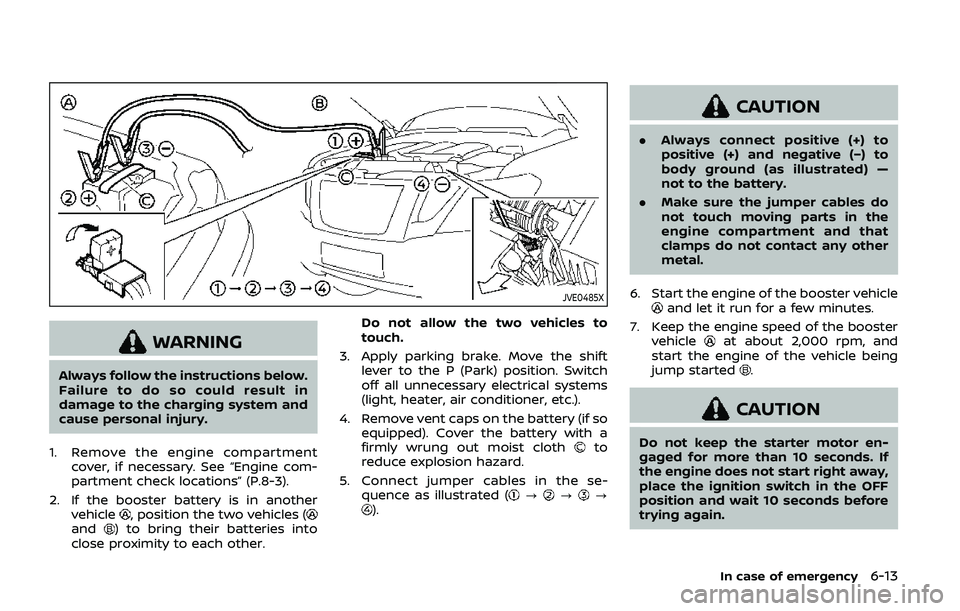
JVE0485X
WARNING
Always follow the instructions below.
Failure to do so could result in
damage to the charging system and
cause personal injury.
1. Remove the engine compartment cover, if necessary. See “Engine com-
partment check locations” (P.8-3).
2. If the booster battery is in another vehicle
, position the two vehicles (and) to bring their batteries into
close proximity to each other. Do not allow the two vehicles to
touch.
3. Apply parking brake. Move the shift lever to the P (Park) position. Switch
off all unnecessary electrical systems
(light, heater, air conditioner, etc.).
4. Remove vent caps on the battery (if so equipped). Cover the battery with a
firmly wrung out moist cloth
to
reduce explosion hazard.
5. Connect jumper cables in the se- quence as illustrated (
???).
CAUTION
.Always connect positive (+) to
positive (+) and negative (−) to
body ground (as illustrated) —
not to the battery.
. Make sure the jumper cables do
not touch moving parts in the
engine compartment and that
clamps do not contact any other
metal.
6. Start the engine of the booster vehicle
and let it run for a few minutes.
7. Keep the engine speed of the booster vehicle
at about 2,000 rpm, and
start the engine of the vehicle being
jump started
.
CAUTION
Do not keep the starter motor en-
gaged for more than 10 seconds. If
the engine does not start right away,
place the ignition switch in the OFF
position and wait 10 seconds before
trying again.
In case of emergency6-13
Page 435 of 536

8 Do-it-yourself
Maintenance precautions ...................................................... 8-2
Engine compartment check locations ........................ 8-3VK56VD engine ....................................................................... 8-3
Engine cooling system ............................................................. 8-4 Checking engine coolant level .................................... 8-5
Changing engine coolant ................................................ 8-5
Engine oil ........................................................................\
..................... 8-6 Checking engine oil level ................................................. 8-6
Changing engine oil and filter ..................................... 8-6
Automatic Transmission Fluid (ATF) ............................. 8-8
Power steering fluid ................................................................... 8-8
Brake fluid ........................................................................\
.................. 8-9
Window washer fluid .............................................................. 8-10
Battery ........................................................................\
........................ 8-11 Jump starting ........................................................................\
. 8-13
Variable voltage control system ................................... 8-13
Drive belts ........................................................................\
................ 8-13
Spark plugs ........................................................................\
............. 8-14 Replacing spark plugs ..................................................... 8-14
Air cleaner ........................................................................\
............... 8-15 Windshield wiper blades ..................................................... 8-16
Cleaning ........................................................................\
........... 8-16
Replacing ........................................................................\
........ 8-16
Rear window wiper blades ............................................... 8-17
Brakes ........................................................................\
........................ 8-17 Self-adjusting brakes ..................................................... 8-17
Brake pad wear warning ............................................ 8-17
Brake booster ...................................................................... 8-17
Fuses ........................................................................\
........................... 8-18 Engine compartment .................................................... 8-18
Passenger compartment ........................................... 8-20
Intelligent Key battery replacement .......................... 8-21
Lights ........................................................................\
.......................... 8-24
Headlights ........................................................................\
...... 8-24
Exterior and interior lights ........................................ 8-26
Wheels and tires ........................................................................\
8-30
Tire pressure ........................................................................\
8-30
Tire labeling ........................................................................\
.. 8-34
Types of tires ....................................................................... 8-36
Tire chains ........................................................................\
...... 8-37
Changing wheels and tires ...................................... 8-37
Page 441 of 536

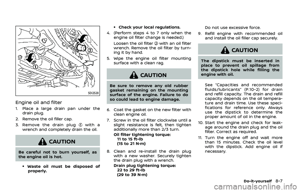
SDI2528
Engine oil and filter
1. Place a large drain pan under thedrain plug.
2. Remove the oil filler cap.
3. Remove the drain plug
with a
wrench and completely drain the oil.
CAUTION
Be careful not to burn yourself, as
the engine oil is hot.
.Waste oil must be disposed of properly.
.Check your local regulations.
4. (Perform steps 4 to 7 only when the engine oil filter change is needed.)
Loosen the oil filter
with an oil filter
wrench. Remove the oil filter by turn-
ing it by hand.
5. Wipe the engine oil filter mounting surface with a clean rag.
CAUTION
Be sure to remove any old rubber
gasket remaining on the mounting
surface of the engine. Failure to do
so could lead to engine damage.
6. Coat the gasket on the new filter with clean engine oil.
7. Screw in the oil filter clockwise until a slight resistance is felt, then tighten
additionally more than 2/3 turn.
Oil filter tightening torque:11 to 15 ft-lb
(15 to 21 N·m)
8. Clean and re-install the drain plug with a new washer. Securely tighten
the drain plug with a wrench.
Drain plug tightening torque:22 to 29 ft-lb
(29 to 39 N·m) Do not use excessive force.
9. Refill engine with recommended oil and install the oil filler cap securely.
CAUTION
The dipstick must be inserted in
place to prevent oil spillage from
the dipstick hole while filling the
engine with oil.
See “Capacities and recommended
fluids/lubricants” (P.10-2) for drain
and refill capacity. The drain and refill
capacity depends on the oil tempera-
ture and drain time. Use these speci-
fications for reference only. Always
use the dipstick to determine the
proper amount of oil in the engine.
10. Start the engine and check for leak- age around the drain plug and the oil
filter. Correct as required.
11. Turn the engine off and wait more than 15 minutes. Check the oil level
with the dipstick. Add engine oil if
necessary.
Do-it-yourself8-7