Page 210 of 592
AUTOMATIC ANTI-GLARE
REARVIEW MIRROR (if so equipped)
The inside mirror is designed so that it
automatically dims during night time con-
ditions and according to the intensity of the
headlights of the vehicle following you. The
automatic anti-glare feature is activated
when the ignition switch is in the ON posi-
tion.NOTE:
Do not hang any objects over the sen-
sors
�1or apply glass cleaner to the sen-
sors. Doing so will reduce the sensitivity
of the sensors, resulting in improper op-
eration.
The indicator light
�2will illuminate when
the automatic anti-glare feature is operat-
ing.
∙ To turn off the anti-glare feature, press the O button. The indicator light will
turn off.
∙ To turn on the anti-glare feature, press the | button. The indicator light will turn
on.
For information on HomeLink® Universal
Transceiver operation, refer to the
“HomeLink® Universal Transceiver” in the
“Instruments and controls” section of this
manual.
OUTSIDE MIRRORS
Page 229 of 592

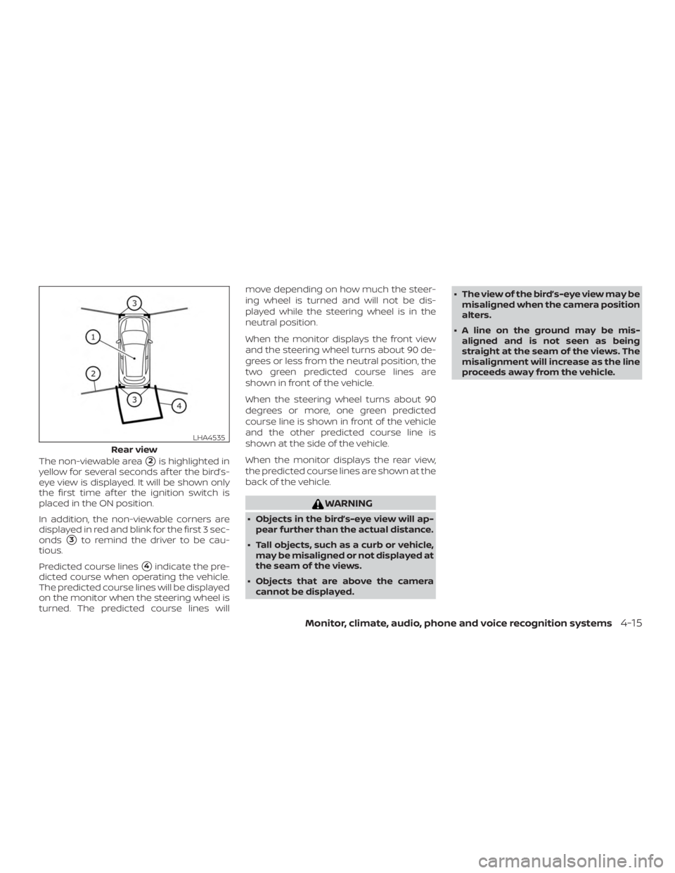
The non-viewable area�2is highlighted in
yellow for several seconds af ter the bird’s-
eye view is displayed. It will be shown only
the first time af ter the ignition switch is
placed in the ON position.
In addition, the non-viewable corners are
displayed in red and blink for the first 3 sec-
onds
�3to remind the driver to be cau-
tious.
Predicted course lines
�4indicate the pre-
dicted course when operating the vehicle.
The predicted course lines will be displayed
on the monitor when the steering wheel is
turned. The predicted course lines will move depending on how much the steer-
ing wheel is turned and will not be dis-
played while the steering wheel is in the
neutral position.
When the monitor displays the front view
and the steering wheel turns about 90 de-
grees or less from the neutral position, the
two green predicted course lines are
shown in front of the vehicle.
When the steering wheel turns about 90
degrees or more, one green predicted
course line is shown in front of the vehicle
and the other predicted course line is
shown at the side of the vehicle.
When the monitor displays the rear view,
the predicted course lines are shown at the
back of the vehicle.
Page 264 of 592

Additional information:∙ When replacing a wheel without the TPMS such as the spare tire, the TPMS
does not monitor the tire pressure of
the spare tire.
∙ The TPMS will activate only when the vehicle is driven at speeds above
16 mph (25 km/h). Also, this system may
not detect a sudden drop in tire pres-
sure (for example, a flat tire while driv-
ing).
∙ The low tire pressure warning light does not automatically turn off when the tire
pressure is adjusted on all four tires. Af-
ter all four tires are inflated to the rec-
ommended pressure, the vehicle must
be driven at speeds above 16 mph
(25 km/h) to activate the TPMS and turn
off the low tire pressure warning light.
Use a tire pressure gauge to check the
tire pressure.
∙ The “Tire Pressure Low - Add Air” warn- ing appears in the vehicle information
display when the low tire pressure
warning light is illuminated and low tire
pressure is detected. The “Tire Pressure
Low - Add Air” warning turns off when
the low tire pressure warning light turns
off. ∙ The “Tire Pressure Low - Add Air” warn-
ing appears each time the ignition
switch is placed in the ON position as
long as the low tire pressure warning
light remains illuminated.
∙ The “Tire Pressure Low - Add Air” warn- ing does not appear if the low tire pres-
sure warning light illuminates to indi-
cate a TPMS malfunction.
∙ Tire pressure rises and falls depending on the heat caused by the vehicle’s op-
eration and the outside temperature.
Do not reduce the tire pressure af ter
driving because the tire pressure rises
af ter driving. Low outside temperature
can lower the temperature of the air
inside the tire which can cause a lower
tire inflation pressure. This may cause
the low tire pressure warning light to
illuminate. If the warning light illumi-
nates, check the tire pressure for all four
tires.
∙ The Tire and Loading Information label is located in the driver’s door opening. ∙ You can also check the tire pressure of
all tires (except the spare) on the vehicle
information display screen. The order of
the tire pressure figures displayed on
the screen corresponds with the actual
order of the tire position.
For additional information, refer to “Low tire
pressure warning light” in the “Instruments
and controls” section, “Tire Pressure Moni-
toring System (TPMS)” in the “In case of
emergency” section and “Tire pressure” in
the “Do-it-yourself ” section of this manual.
Page 271 of 592

WARNING
Do not operate the push-button igni-
tion switch while driving the vehicle ex-
cept in an emergency. (The engine will
stop when the ignition switch is pushed
three consecutive times in quick suc-
cession or the ignition switch is pushed
and held for more than 2 seconds.) If the
engine stops while the vehicle is being
driven, this could lead to a crash and
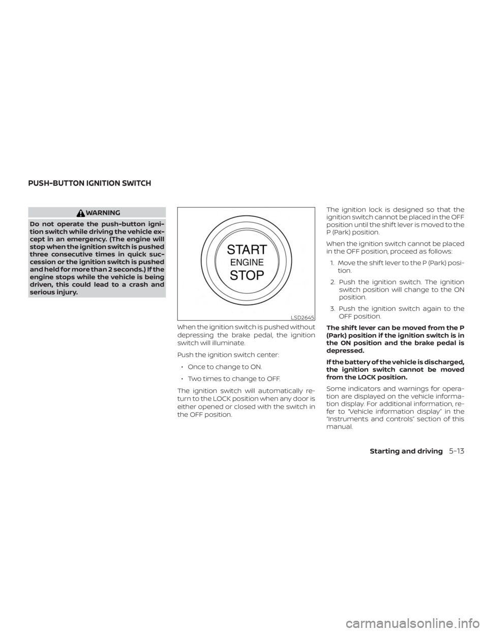
serious injury.When the ignition switch is pushed without
depressing the brake pedal, the ignition
switch will illuminate.
Push the ignition switch center:∙ Once to change to ON.
∙ Two times to change to OFF.
The ignition switch will automatically re-
turn to the LOCK position when any door is
either opened or closed with the switch in
the OFF position. The ignition lock is designed so that the
ignition switch cannot be placed in the OFF
position until the shif t lever is moved to the
P (Park) position.
When the ignition switch cannot be placed
in the OFF position, proceed as follows:
1. Move the shif t lever to the P (Park) posi- tion.
2. Push the ignition switch. The ignition switch position will change to the ON
position.
3. Push the ignition switch again to the OFF position.
The shif t lever can be moved from the P
(Park) position if the ignition switch is in
the ON position and the brake pedal is
depressed.
If the battery of the vehicle is discharged,
the ignition switch cannot be moved
from the LOCK position.
Some indicators and warnings for opera-
tion are displayed on the vehicle informa-
tion display. For additional information, re-
fer to “Vehicle information display” in the
“Instruments and controls” section of this
manual.
Page 272 of 592

OPERATING RANGE
The Intelligent Key functions can only be
used when the Intelligent Key is within the
specified operating range.
When the Intelligent Key battery is almost
discharged or strong radio waves are pres-
ent near the operating location, the Intelli-
gent Key system’s operating range becomes
narrower and may not function properly.
If the Intelligent Key is within the operating
range, it is possible for anyone, even some-
one who does not carry the Intelligent Key, to
push the ignition switch to start the engine.
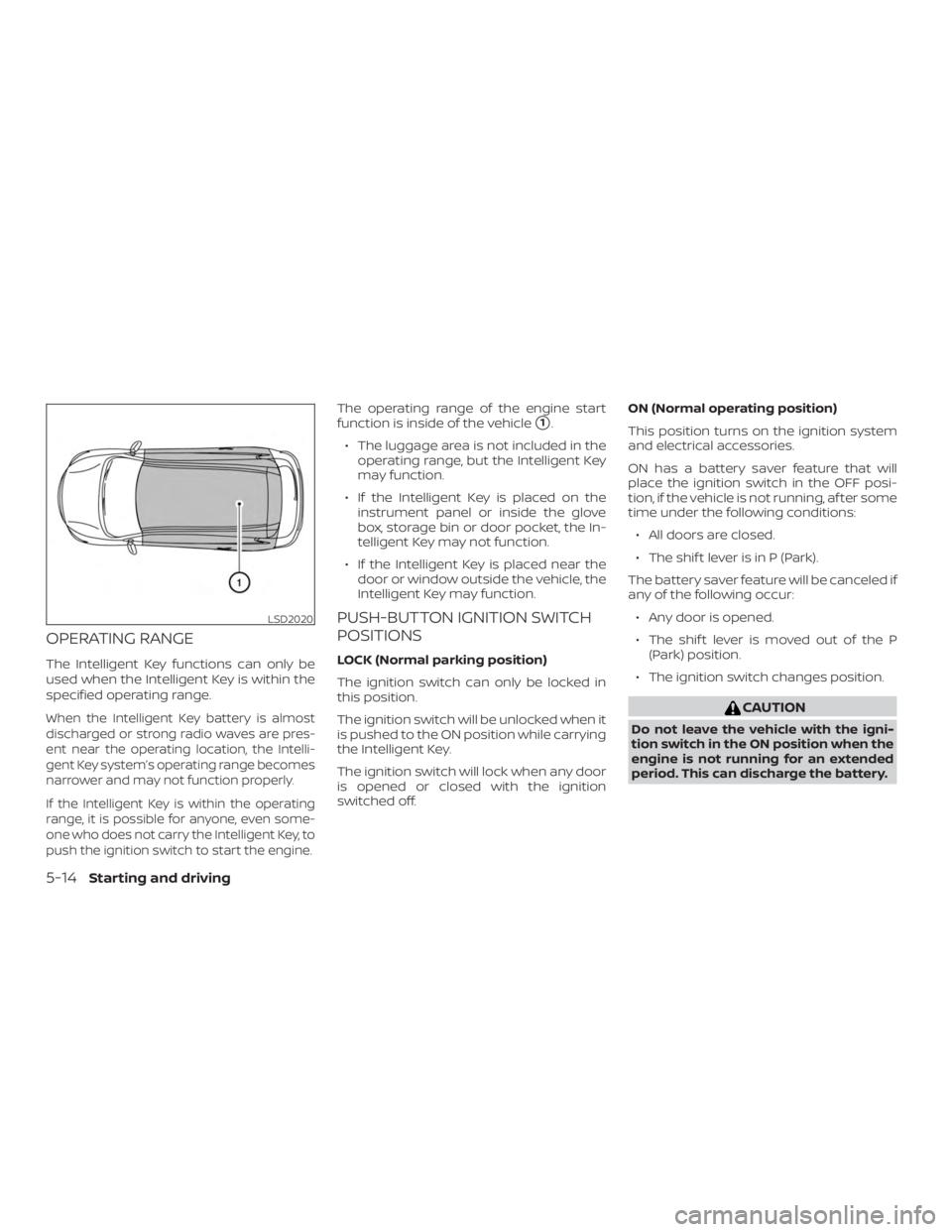
The operating range of the engine start
function is inside of the vehicle
�1.
∙ The luggage area is not included in the operating range, but the Intelligent Key
may function.
∙ If the Intelligent Key is placed on the instrument panel or inside the glove
box, storage bin or door pocket, the In-
telligent Key may not function.
∙ If the Intelligent Key is placed near the door or window outside the vehicle, the
Intelligent Key may function.
PUSH-BUTTON IGNITION SWITCH
POSITIONS
LOCK (Normal parking position)
The ignition switch can only be locked in
this position.
The ignition switch will be unlocked when it
is pushed to the ON position while carrying
the Intelligent Key.
The ignition switch will lock when any door
is opened or closed with the ignition
switched off. ON (Normal operating position)
This position turns on the ignition system
and electrical accessories.
ON has a battery saver feature that will
place the ignition switch in the OFF posi-
tion, if the vehicle is not running, af ter some
time under the following conditions:
∙ All doors are closed.
∙ The shif t lever is in P (Park).
The battery saver feature will be canceled if
any of the following occur: ∙ Any door is opened.
∙ The shif t lever is moved out of the P (Park) position.
∙ The ignition switch changes position.
Page 275 of 592

1. Apply the parking brake.
2. Move the shif t lever to P (Park) or N(Neutral). P (Park) is recommended.
The starter is designed not to oper-
ate if the shif t lever is in any of the
driving positions.
3. Push the ignition switch to the ON po- sition. Depress the brake pedal and
push the ignition switch to start the
engine.
To start the engine immediately, push
and release the ignition switch while
depressing the brake pedal with the
ignition switch in any position.
∙ If the engine is very hard to start in extremely cold weather or when re-
starting, depress the accelerator
pedal a little (approximately 1/3 to the
floor) and while holding, crank the en-
gine. Release the accelerator pedal
when the engine starts.
∙ If the engine is very hard to start be- cause it is flooded, depress the accel-
erator pedal all the way to the floor
and hold it. Push the ignition switch
to the ON position to start cranking
the engine. Af ter 5 or 6 seconds, stop
cranking by pushing the ignition switch to the LOCK position. Af ter
cranking the engine, release the ac-
celerator pedal. Crank the engine
with your foot off the accelerator
pedal by depressing the brake pedal
and pushing the ignition switch to
start the engine. If the engine starts,
but fails to run, repeat the above pro-
cedure.
Page 276 of 592
REMOTE ENGINE START (if so
equipped)
Vehicles started with the Remote Engine
Start require the ignition switch to be
placed in the ON position before the shif t
lever can be moved from the P (Park) posi-
tion. To place the ignition switch in the ON
position, follow these steps:1. Make sure that the Intelligent Key is on you.
2. Apply the brake.
3. Push the ignition switch once to the ON position.
For additional information, refer to “NISSAN
Intelligent Key®” in the “Pre-driving checks
and adjustments” section of this manual.
CONTINUOUSLY VARIABLE
TRANSMISSION (CVT)
Page 283 of 592
Fail-safe
If the vehicle is driven under extreme
conditions, such as excessive wheel
spinning and subsequent hard braking,
the fail-safe system may be activated.
The Malfunction Indicator Light (MIL)
may come on to indicate the fail-safe
mode is activated. For additional infor-
mation, refer to “Malfunction Indicator
Light (MIL)” in the “Instruments and con-
trols” section of this manual. This will oc-
cur even if all electrical circuits are func-
tioning properly. In this case, place the
ignition switch in the OFF position and
wait for 10 seconds. Then push the
switch back to the ON position. The ve-
hicle should return to its normal operat-
ing condition. If it does not return to its
normal operating condition, have the
transmission checked. It is recom-
mended that you visit a NISSAN dealer
for this service.