Page 190 of 592
Lockout protection
To prevent the Intelligent Key from being
accidentally locked in the vehicle, lockout
protection is equipped with the Intelligent
Key.
When the driver’s side door is open, the
doors are locked and then the Intelligent
Key is put inside the vehicle and all the
doors are closed; the lock will automati-
cally unlock and the door chime sounds.
NOTE:
The doors may not lock when the Intelli-
gent Key is in the same hand that is op-
erating the request switch to lock the
door. Put the Intelligent Key in a purse,
pocket or your other hand.
Page 192 of 592
Lockout protection
To prevent the Intelligent Key from being
accidentally locked in the trunk, lockout
protection is equipped with the Intelligent
Key.
When all doors are locked and the trunk lid
is closed with the Intelligent Key inside the
trunk, the outside buzzer will sound and the
trunk will open.
HOW TO USE THE REMOTE
KEYLESS ENTRY FUNCTION
The remote keyless entry function can op-
erate all door locks using the remote key-
less function of the Intelligent Key. The re-
mote keyless function can operate at a
distance of 33 f t (10 m) away from the ve-
hicle. The operating distance depends
upon the conditions around the vehicle.
The remote keyless entry function may not
function under the following conditions:∙ When the Intelligent Key is not within the operational range.
∙ When the doors or the trunk are open or not closed securely.
∙ When the Intelligent Key battery is dis- charged.
Page 193 of 592
CAUTION
Af ter locking the doors using the Intel-
ligent Key, be sure that the doors have
been securely locked by operating the
door handles.
Unlocking doors
1. Press the
Page 204 of 592
NOTE:
Request switches for all doors and trunk
can be deactivated when the I-Key Door
Lock setting is switched to OFF in the
“Vehicle Settings” of the vehicle informa-
tion display. For additional information,
refer to “Vehicle information display ” in
the “Instruments and controls” section
of the manual.
INTERIOR TRUNK LID RELEASE
Page 205 of 592

WARNING
∙ Never allow anyone to ride in thecargo area or on the rear seat when it
is in the fold-down position. Use of
these areas by passengers without
proper restraints could result in seri-
ous injury or death in an accident or
sudden stop.
∙ Properly secure all cargo with ropes or straps to help prevent it from sliding
or shif ting. Do not place cargo higher
than the seatbacks. In a sudden stop
or collision, unsecured cargo could
cause personal injury.
∙ When returning the seatbacks to the upright position, be certain they are
completely secured in the latched po-
sition. If they are not completely se-
cured, passengers may be injured in
an accident or sudden stop.
∙ Closely supervise children when they are around cars to prevent them from
playing and becoming locked in the
trunk where they could be seriously
injured. Keep the car locked, with the
rear seatback and trunk lid securely
latched when not in use, and prevent
children’s access to car keys.
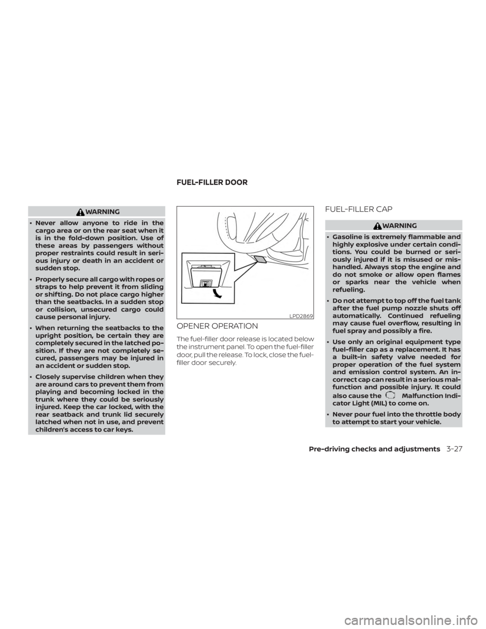
OPENER OPERATION
The fuel-filler door release is located below
the instrument panel. To open the fuel-filler
door, pull the release. To lock, close the fuel-
filler door securely.
FUEL-FILLER CAP
Page 271 of 592

WARNING
Do not operate the push-button igni-
tion switch while driving the vehicle ex-
cept in an emergency. (The engine will
stop when the ignition switch is pushed
three consecutive times in quick suc-
cession or the ignition switch is pushed
and held for more than 2 seconds.) If the
engine stops while the vehicle is being
driven, this could lead to a crash and
serious injury.When the ignition switch is pushed without
depressing the brake pedal, the ignition
switch will illuminate.
Push the ignition switch center:∙ Once to change to ON.
∙ Two times to change to OFF.
The ignition switch will automatically re-
turn to the LOCK position when any door is
either opened or closed with the switch in
the OFF position. The ignition lock is designed so that the
ignition switch cannot be placed in the OFF
position until the shif t lever is moved to the
P (Park) position.
When the ignition switch cannot be placed
in the OFF position, proceed as follows:
1. Move the shif t lever to the P (Park) posi- tion.
2. Push the ignition switch. The ignition switch position will change to the ON
position.
3. Push the ignition switch again to the OFF position.
The shif t lever can be moved from the P
(Park) position if the ignition switch is in
the ON position and the brake pedal is
depressed.
If the battery of the vehicle is discharged,
the ignition switch cannot be moved
from the LOCK position.
Some indicators and warnings for opera-
tion are displayed on the vehicle informa-
tion display. For additional information, re-
fer to “Vehicle information display” in the
“Instruments and controls” section of this
manual.
Page 272 of 592

OPERATING RANGE
The Intelligent Key functions can only be
used when the Intelligent Key is within the
specified operating range.
When the Intelligent Key battery is almost
discharged or strong radio waves are pres-
ent near the operating location, the Intelli-
gent Key system’s operating range becomes
narrower and may not function properly.
If the Intelligent Key is within the operating
range, it is possible for anyone, even some-
one who does not carry the Intelligent Key, to
push the ignition switch to start the engine.
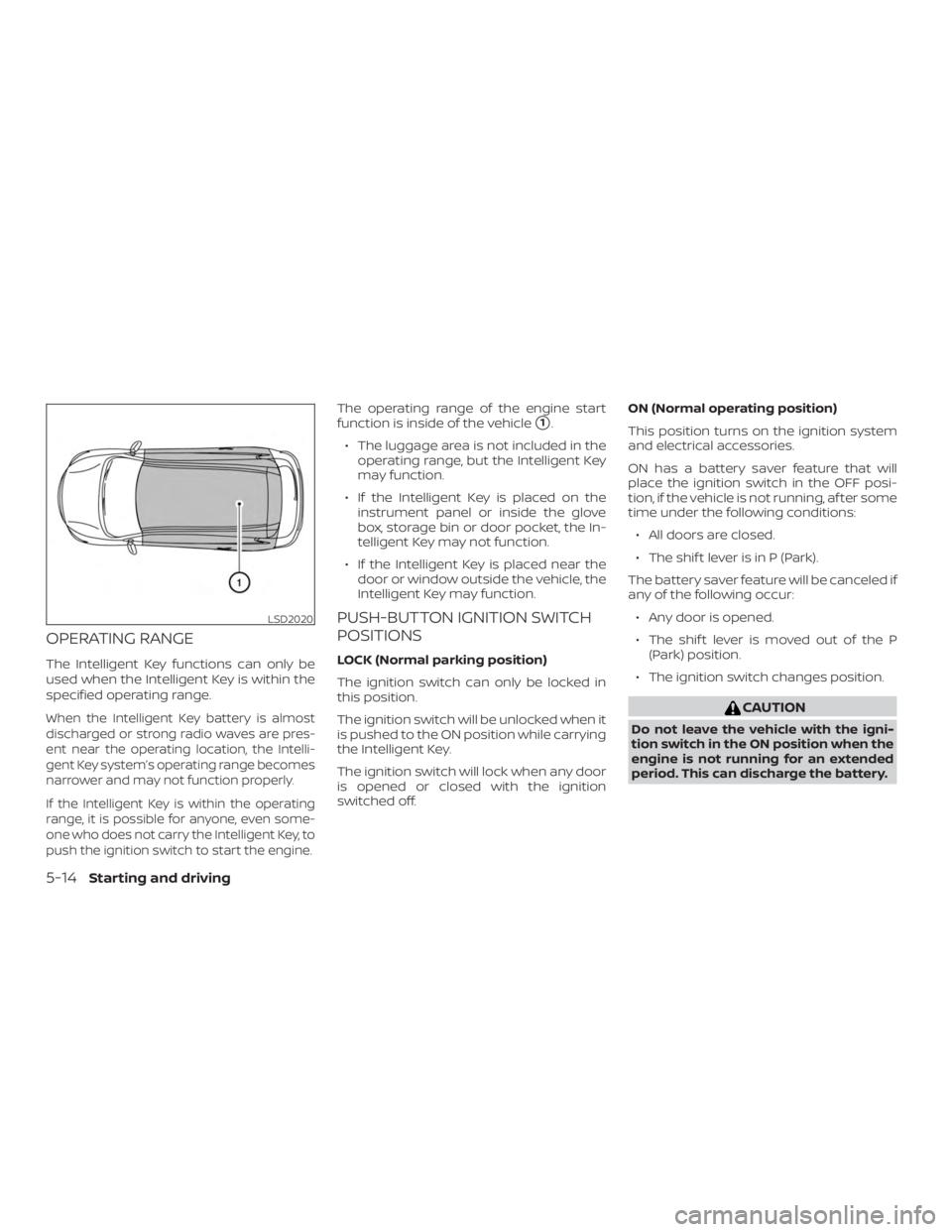
The operating range of the engine start
function is inside of the vehicle
�1.
∙ The luggage area is not included in the operating range, but the Intelligent Key
may function.
∙ If the Intelligent Key is placed on the instrument panel or inside the glove
box, storage bin or door pocket, the In-
telligent Key may not function.
∙ If the Intelligent Key is placed near the door or window outside the vehicle, the
Intelligent Key may function.
PUSH-BUTTON IGNITION SWITCH
POSITIONS
LOCK (Normal parking position)
The ignition switch can only be locked in
this position.
The ignition switch will be unlocked when it
is pushed to the ON position while carrying
the Intelligent Key.
The ignition switch will lock when any door
is opened or closed with the ignition
switched off. ON (Normal operating position)
This position turns on the ignition system
and electrical accessories.
ON has a battery saver feature that will
place the ignition switch in the OFF posi-
tion, if the vehicle is not running, af ter some
time under the following conditions:
∙ All doors are closed.
∙ The shif t lever is in P (Park).
The battery saver feature will be canceled if
any of the following occur: ∙ Any door is opened.
∙ The shif t lever is moved out of the P (Park) position.
∙ The ignition switch changes position.
Page 558 of 592

Top tether strap anchor point
locations...................1-28
Child safety rear door lock ..........3-7
Chimes, audible reminders .........2-18
Cleaningexteriorandinterior......7-2,7-4
C.M.V.S.S. certification label .........10-11
Coldweatherdriving.............5-181
Console box ..................2-57
Continuously Variable Transmission
(CVT) .......................5-18
Continuously Variable Transmission
(CVT) fluid ..................8-13
Driving with Continuously Variable
Transmission (CVT) ............5-18
Controls Heater and air conditioner
controls................4-29,4-38
Coolant Capacities and recommended
fuel/lubricants...............10-2
Changing engine coolant .........8-7
Checking engine coolant level ......8-7
Engine coolant temperature gauge . .2-6
Corrosionprotection..............7-7
Cruisecontrol.................5-64
Cupholders...............2-58,2-59
D
Daytime Running Light System ......2-48
Defroster switch Rear window and outside mirror
defrosterswitch..............2-43
Dimensions and weights ...........10-9
Dimmer switch for instrument panel . . .2-49 Door locks
..................3-4,3-5
Drivebelt.....................8-17
Drive positioner, Automatic . . .3-33, 3-34, 3-35
Driving Cold weather driving ...........5-181
Driving with Continuously Variable
Transmission (CVT) ............5-18
Precautions when starting and
driving..................5-4,5-11
Drivingthevehicle...............5-18
E
E-CALL (SOS) SWITCH .............2-53
Economy - fuel ................5-165
Emergency engine shutoff .......5-15,6-2
Emission control information label . . . .10-12
Emission control system warranty . . . .10-18
Engine Before starting the engine ........5-16
Capacities and recommended
fuel/lubricants...............10-2
Changing engine coolant .........8-7
Changing engine oil ............8-9
Changing engine oil filter .........8-9
Checking engine coolant level ......8-7
Checking engine oil level .........8-8
Engine compartment check
locations...................8-4
Engine coolant temperature gauge . .2-6
Engine cooling system ..........8-6
Engine oil ...................8-8
Engine oil and oil filter
recommendation .............10-6
Engine oil pressure warning light ....2-12Engine oil viscosity
.............10-7
Engine serial number ...........10-11
Engine specifications ...........10-8
Starting the engine ............5-17
Engine Block Heater .............5-183
Engine coolant temperature gauge ....2-6
EventDatarecorders.........10-20,10-21
Exhaust gas (Carbon monoxide) .......5-4
Explanation of maintenance items .....9-3
Explanation of scheduled maintenance
items .......................9-5
Extended storage switch ..........2-55
Eyeglasscase.................2-58
F
Flashers
(Seehazardwarningflasherswitch)....6-2
Flattire....................6-3,6-4
Floormatpositioningaid...........7-6
Fluid Brakefluid..................8-13
Capacities and recommended
fuel/lubricants...............10-2
Continuously Variable Transmission
(CVT) fluid ..................8-13
Engine coolant ...............
8-6
Engine oil ...................8-8
Windshield-washer fluid .........8-14
F.M.V.S.S. certification label ..........10-11
Foglightswitch................2-50
Front air bag system (See supplemental
restraintsystem)................1-53
Front-door pocket ..............2-56
Front power seat adjustment ........1-4
11-2