Page 149 of 592
To defrost the rear window glass and out-
side mirrors (if so equipped), place the igni-
tion switch in the ON position and push the
rear window defroster switch on. The rear
window defroster indicator light on the
switch comes on. Push the switch again to
turn the defroster off.
The rear window defroster automatically
turns off af ter approximately 15 minutes.
Page 152 of 592

– When the headlights of the on-coming vehicle or the leading ve-
hicle are turned off, when the color
of the light is affected due to for-
eign materials on the lights, or
when the light beam is out of
position.
– When there is a sudden, continu- ous change in brightness.
– When driving on a road that passes over rolling hills, or a road that has
level differences.
– When driving on a road with many curves.
– When a sign or mirror-like surface is reflecting intense light towards
the front of the vehicle.
– When the container, etc. being towed by a leading vehicle is re-
flecting intense light.
– When a headlight on your vehicle is damaged or dirty.
– When the vehicle is leaning at an angle due to a punctured tire, be-
ing towed, etc. ∙ The timing of switching the low beam
and high beam may change under the
following situations.
– The brightness of the headlights of the oncoming vehicle or leading
vehicle.
– The movement and direction of the oncoming vehicle and the lead-
ing vehicle.
– When only one light on the oncom- ing vehicle or the leading vehicle is
illuminated.
– When the oncoming vehicle or the leading vehicle is a two-wheeled
vehicle.
– Road conditions (incline, curve, the road surface, etc.).
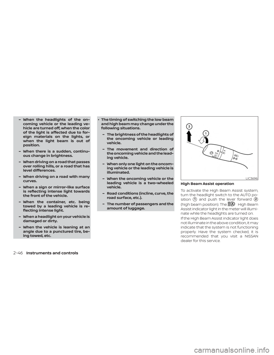
– The number of passengers and the amount of luggage. High Beam Assist operation
To activate the High Beam Assist system,
turn the headlight switch to the AUTO po-
sition
�1and push the lever forward�2
(high beam position). The
Page 210 of 592
AUTOMATIC ANTI-GLARE
REARVIEW MIRROR (if so equipped)
The inside mirror is designed so that it
automatically dims during night time con-
ditions and according to the intensity of the
headlights of the vehicle following you. The
automatic anti-glare feature is activated
when the ignition switch is in the ON posi-
tion.NOTE:
Do not hang any objects over the sen-
sors
�1or apply glass cleaner to the sen-
sors. Doing so will reduce the sensitivity
of the sensors, resulting in improper op-
eration.
The indicator light
�2will illuminate when
the automatic anti-glare feature is operat-
ing.
∙ To turn off the anti-glare feature, press the O button. The indicator light will
turn off.
∙ To turn on the anti-glare feature, press the | button. The indicator light will turn
on.
For information on HomeLink® Universal
Transceiver operation, refer to the
“HomeLink® Universal Transceiver” in the
“Instruments and controls” section of this
manual.
OUTSIDE MIRRORS
Page 218 of 592
WARNING
∙ Failure to follow the warnings and in-structions for proper use of the Rear-
View Monitor system could result in
serious injury or death.
∙ RearView Monitor is a convenience feature and is not a substitute for
proper backing. Always turn and look
out the windows and check mirrors to
be sure that it is safe to move before
operating the vehicle. Always back up
slowly.
∙ The system is designed as an aid to the driver in showing large stationary
objects directly behind the vehicle, to
help avoid damaging the vehicle.
∙ The distance guide lines and the ve- hicle width lines should be used as a
reference only when the vehicle is on a
level paved surface. The distance
viewed on the monitor is for reference
only and may be different than the
actual distance between the vehicle
and displayed objects.
Page 238 of 592

WARNING
Failure to follow the warnings and in-
structions for proper use of the Moving
Object Detection (MOD) system could
result in serious injury or death
∙ The MOD system is not a substitutefor proper vehicle operation and is not
designed to prevent contact with ob-
jects surrounding the vehicle. When
maneuvering, always use the outside
mirrors and rearview mirror and turn
and check the surroundings to ensure
it is safe to maneuver.
∙ The system is deactivated at speeds above 5 mph (8 km/h). It is reactivated
at lower speeds.
∙
The MOD system is not designed to de-
tect surrounding stationary objects.
The MOD system can inform the driver of
moving objects near the vehicle when
backing out of garages, maneuvering in
parking lots and in other such instances.
The MOD system detects moving objects
by using image processing technology on
the image shown in the display.
MOD SYSTEM OPERATION
The MOD system will turn on automatically
under the following conditions:
∙ When the shif t lever is in the R (Reverse) position.
∙ When the CAMERA button is pressed to activate the camera view on the display.
∙ When vehicle speed decreases below approximately 6 mph (10 km/h) and the
camera screen is displayed.
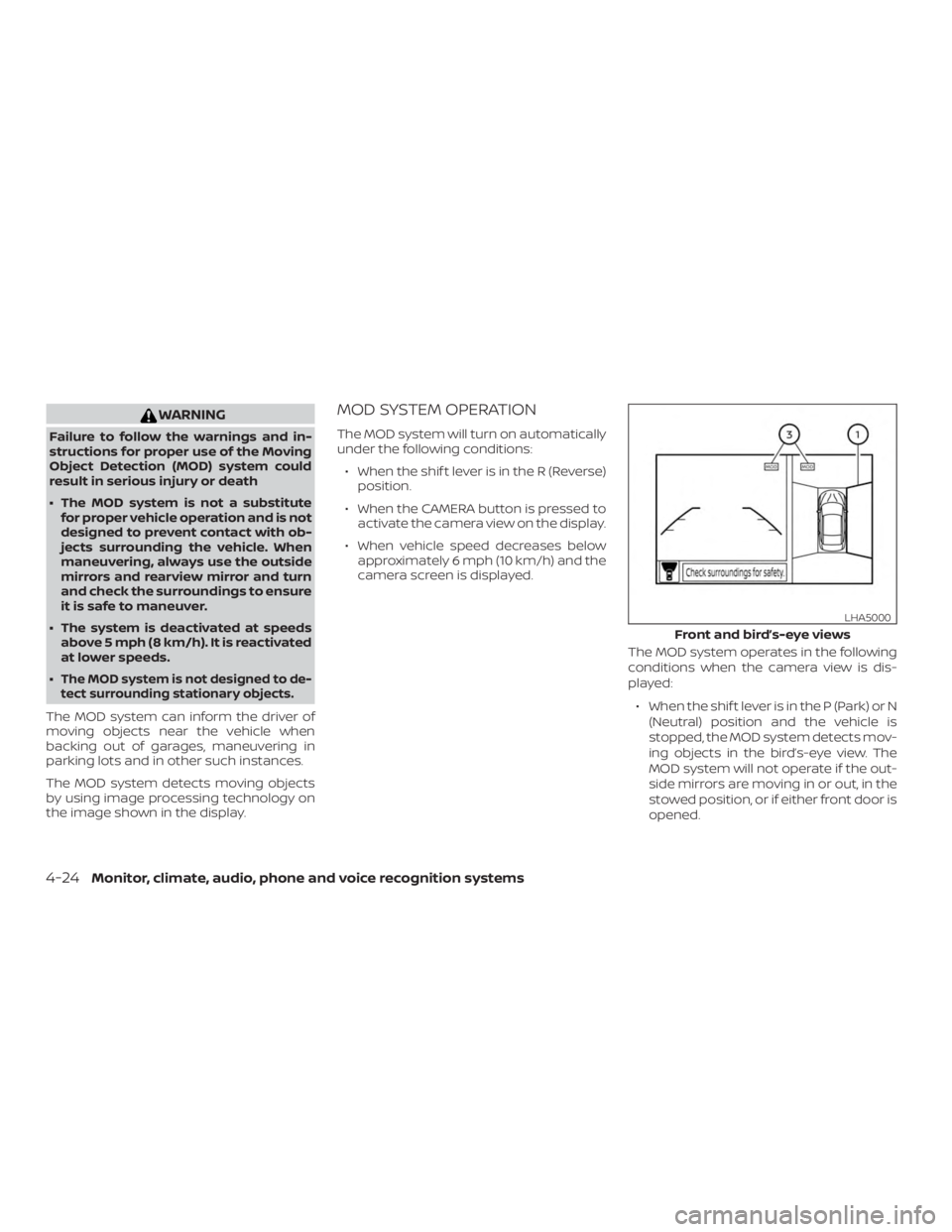
The MOD system operates in the following
conditions when the camera view is dis-
played:∙ When the shif t lever is in the P (Park) or N (Neutral) position and the vehicle is
stopped, the MOD system detects mov-
ing objects in the bird’s-eye view. The
MOD system will not operate if the out-
side mirrors are moving in or out, in the
stowed position, or if either front door is
opened.
Page 289 of 592
∙When the vehicle stops, but the brake
force is not automatically applied, de-
press the brake pedal firmly until the
automatic brake hold indicator light
(green) illuminates.
The TSR system provides the driver with
information about the most recently de-
tected speed limit. The system captures
the road sign information with the multi-
sensing front camera unit
�1located on
the windshield in front of the inside rear-
view mirror and displays the detected
signs in the vehicle information display. For
vehicles equipped with a navigation sys-
tem, the speed limit displayed is based on a
combination of navigation system data
and live camera recognition. TSR informa-
tion is always displayed at the top of the
vehicle information display, and optionally
in the main central area of the display
screen.
Page 297 of 592
∙ Do not place reflective materials, suchas white paper or a mirror, on the instru-
ment panel. The reflection of sunlight
may adversely affect the camera unit’s
capability of detecting the lane mark-
ers.
∙ Do not strike or damage the areas around the camera unit. Do not touch
the camera lens or remove the screw
located on the camera unit. If the cam-
era unit is damaged due to an accident,
it is recommended that you visit a
NISSAN dealer.
Page 303 of 592
WARNING
Failure to follow the warnings and in-
structions for proper use of the BSW
system could result in serious injury or
death.
∙ The BSW system is not a replacementfor proper driving procedures and is
not designed to prevent contact with
vehicles or objects. When changing
lanes, always use the side and rear
mirrors and turn and look in the direc-
tion your vehicle will move to ensure it
is safe to change lanes. Never rely
solely on the BSW system.
The BSW system helps alert the driver of
other vehicles in adjacent lanes when
changing lanes. The BSW system uses radar sensors
�1
installed near the rear bumper to detect
other vehicles in an adjacent lane.
The radar sensors can detect vehicles on
either side of your vehicle within the detec-
tion zone shown as illustrated. This detec-
tion zone starts from the outside mirror of
your vehicle and extends approximately
10 f t (3.0 m) behind the rear bumper, and
approximately 10 f t (3.0 m) sideways.