Page 208 of 592
TILT OPERATION
Pull the lock lever down and hold on until
the end of the stroke
�1and adjust the
steering wheel up or down
�2to the de-
sired position.
Push the lock lever up
�1firmly and hold on
until end of stroke to lock the steering
wheel in place.
TELESCOPIC OPERATION
Pull the lock lever down�1and adjust the
steering wheel forward or backward
�3to
the desired position.
Push the lock lever up
�1firmly and hold on
until end of stroke to lock the steering
wheel in place.
LPD2871
WPD0344
SUN VISORS
3-30Pre-driving checks and adjustments
Page 212 of 592

MEMORY STORAGE FUNCTION
(key-link)
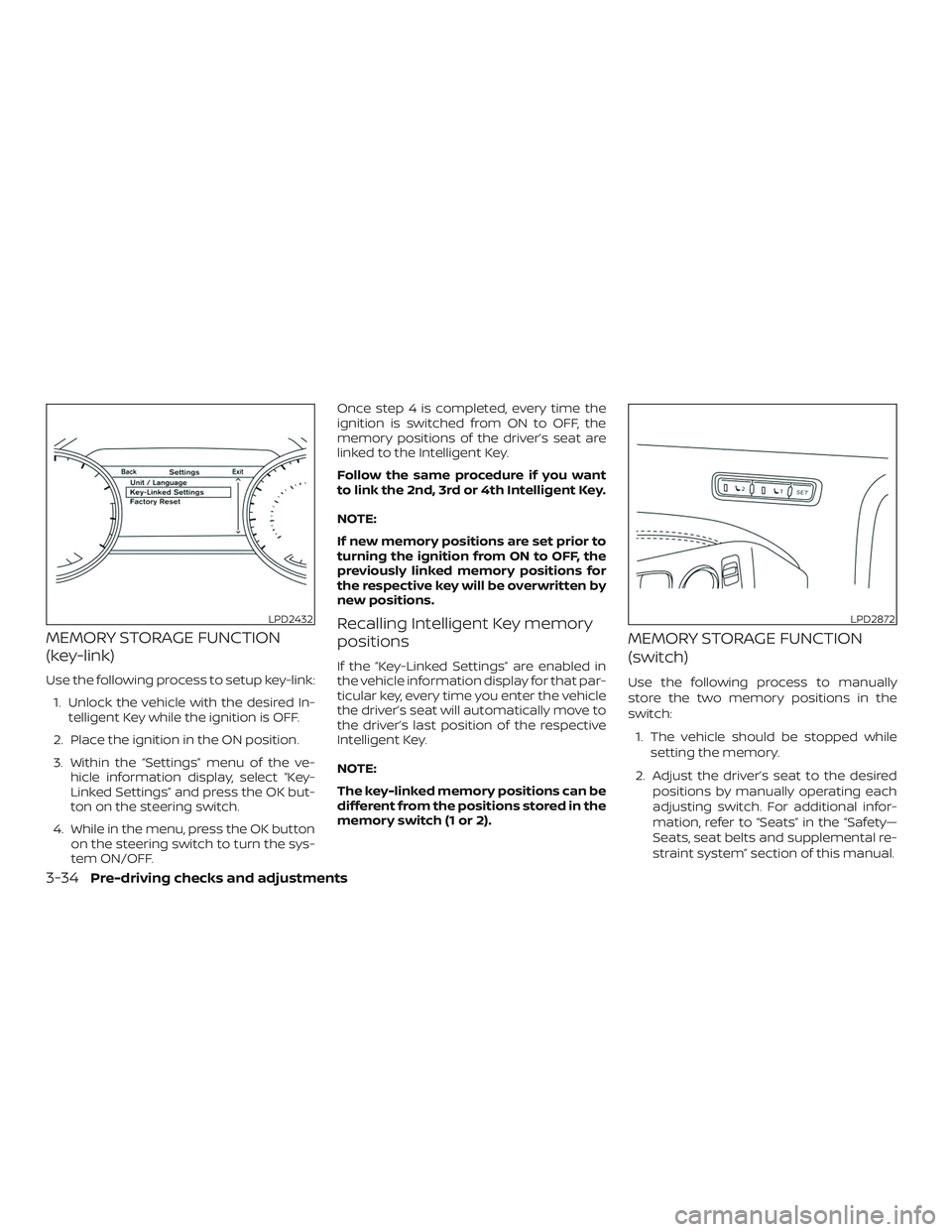
Use the following process to setup key-link:1. Unlock the vehicle with the desired In- telligent Key while the ignition is OFF.
2. Place the ignition in the ON position.
3. Within the “Settings” menu of the ve- hicle information display, select “Key-
Linked Settings” and press the OK but-
ton on the steering switch.
4. While in the menu, press the OK button on the steering switch to turn the sys-
tem ON/OFF. Once step 4 is completed, every time the
ignition is switched from ON to OFF, the
memory positions of the driver’s seat are
linked to the Intelligent Key.
Follow the same procedure if you want
to link the 2nd, 3rd or 4th Intelligent Key.
NOTE:
If new memory positions are set prior to
turning the ignition from ON to OFF, the
previously linked memory positions for
the respective key will be overwritten by
new positions.
Recalling Intelligent Key memory
positions
If the “Key-Linked Settings” are enabled in
the vehicle information display for that par-
ticular key, every time you enter the vehicle
the driver’s seat will automatically move to
the driver’s last position of the respective
Intelligent Key.
NOTE:
The key-linked memory positions can be
different from the positions stored in the
memory switch (1 or 2).
MEMORY STORAGE FUNCTION
(switch)
Use the following process to manually
store the two memory positions in the
switch:
1. The vehicle should be stopped while setting the memory.
2. Adjust the driver’s seat to the desired positions by manually operating each
adjusting switch. For additional infor-
mation, refer to “Seats” in the “Safety—
Seats, seat belts and supplemental re-
straint system” section of this manual.
LPD2432LPD2872
3-34Pre-driving checks and adjustments
Page 219 of 592

HOW TO READ THE DISPLAYED
LINES
Guiding lines which indicate the vehicle
width and distances to objects with refer-
ence to the vehicle body line
�Aare dis-
played on the monitor.
Distance guide lines
Indicate distances from the vehicle body.
∙ Red line
�1: approx. 1.5 f t (0.5 m)
∙ Yellow line
�2: approx. 3 f t (1 m)
∙ Green line
�3: approx. 7 f t (2 m) Vehicle width guide lines
�4
Indicate the vehicle width when backing
up.
Predicted course lines
�5
Indicate the predicted course when back-
ing up. The predicted course lines will be
displayed on the monitor when the shif t
lever is in the R (Reverse) position and the
steering wheel is turned. The predicted
course lines will move depending on how
much the steering wheel is turned and will
not be displayed while the steering wheel is
in the straight-ahead position.
The vehicle width guide lines and the width
of the predicted course lines are wider than
the actual width and course.
DIFFERENCE BETWEEN PREDICTED
AND ACTUAL DISTANCES
The displayed guidelines and their loca-
tions on the ground are for approximate
reference only. Objects on uphill or downhill
surfaces or projecting objects will be actu-
ally located at distances different from
those displayed in the monitor relative to
the guidelines (refer to illustrations). When
in doubt, turn around and view the objects as you are backing up, or park and exit the
vehicle to view the positioning of objects
behind the vehicle.
LHA4805
Monitor, climate, audio, phone and voice recognition systems4-5
Page 221 of 592

Backing up behind a projecting
object
The position�Cis shown farther than the
position
�Bin the display. However, the po-
sition
�Cis actually at the same distance as
the position
�A. The vehicle may hit the object when backing up to the position
�A
if the object projects over the actual back-
ing up course.
HOW TO PARK WITH PREDICTED
COURSE LINES
WARNING
∙ If the tires are replaced with different
sized tires, the predicted course lines
may be displayed incorrectly.
∙ On a snow-covered or slippery road, there may be a difference between
the predicted course line and the ac-
tual course line.
∙ If the battery is disconnected or be- comes discharged, the predicted
course lines may be displayed incor-
rectly. If this occurs, please perform
the following procedures:
– Turn the steering wheel from lock to lock while the engine is running.
– Drive the vehicle on a straight road for more than 5 minutes.
∙ When the steering wheel is turned with the ignition switch in the ACC po-
sition, the predicted course lines may
be displayed incorrectly. 1. Visually check that the parking space is
safe before parking your vehicle.
2. The rear view of the vehicle is displayed on the screen
�Awhen the shif t lever is
moved to the R (Reverse) position.
LHA4945LHA5043
Monitor, climate, audio, phone and voice recognition systems4-7
Page 222 of 592
3. Slowly back up the vehicle adjustingthe steering wheel so that the pre-
dicted course lines
�Benter the park-
ing space
�C. 4. Maneuver the steering wheel to make
the vehicle width guide lines
�Dparallel
to the parking space
�Cwhile referring
to the predicted course lines.
5. When the vehicle is parked in the space completely, move the shif t lever to the
P (Park) position and apply the parking
brake.
ADJUSTING THE SCREEN
1. Press the CAMERA button.
2. Touch the “Display Settings” key.
3. Touch the “Brightness”, “Contrast”, Tint”,“Color”, or “Black Level” key.
4. Adjust the item by touching the “+” or “–” key on the touch-screen display.
NOTE:
Do not adjust any of the display settings
of the RearView Monitor while the ve-
hicle is moving.
LHA4770
LHA3522
4-8Monitor, climate, audio, phone and voice recognition systems
Page 228 of 592

∙ Green line�4: approximately 10 f t (3 m)
(if so equipped)
Vehicle width guide lines
�5:
Indicate the approximate vehicle width
when backing up.
Predicted course lines
�6:
Indicate the predicted course when oper-
ating the vehicle. The predicted course
lines will be displayed on the monitor when
the steering wheel is turned. The predicted
course lines will move depending on how
much the steering wheel is turned and will not be displayed while the steering wheel is
in the straight-ahead position.
The front view will not be displayed when
the vehicle speed is above 6 mph (10 km/h).
NOTE:
When the monitor displays the front
view and the steering wheel turns about
90 degrees or less from the straight-
ahead position, both the right and lef t
predicted course lines
�6are displayed.
When the steering wheel turns about 90
degrees or more, a line is displayed only
on the opposite side of the turn.
Bird’s-eye view
The bird’s-eye view shows the overhead
view of the vehicle, which helps confirm the
vehicle position and the predicted course
to a parking space.
The vehicle icon
�1shows the position of
the vehicle. Note that the apparent dis-
tance between objects viewed in the bird’s-
eye view may differ somewhat from the
actual distance to the vehicle.
The areas that the cameras cannot cover
�2are indicated in black.
Rear view
LHA4992
Front view
LHA4534
4-14Monitor, climate, audio, phone and voice recognition systems
Page 229 of 592

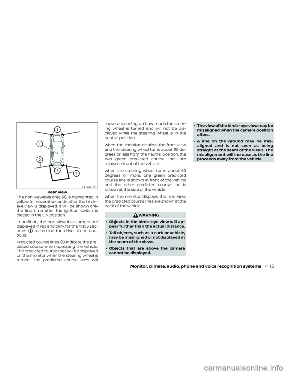
The non-viewable area�2is highlighted in
yellow for several seconds af ter the bird’s-
eye view is displayed. It will be shown only
the first time af ter the ignition switch is
placed in the ON position.
In addition, the non-viewable corners are
displayed in red and blink for the first 3 sec-
onds
�3to remind the driver to be cau-
tious.
Predicted course lines
�4indicate the pre-
dicted course when operating the vehicle.
The predicted course lines will be displayed
on the monitor when the steering wheel is
turned. The predicted course lines will move depending on how much the steer-
ing wheel is turned and will not be dis-
played while the steering wheel is in the
neutral position.
When the monitor displays the front view
and the steering wheel turns about 90 de-
grees or less from the neutral position, the
two green predicted course lines are
shown in front of the vehicle.
When the steering wheel turns about 90
degrees or more, one green predicted
course line is shown in front of the vehicle
and the other predicted course line is
shown at the side of the vehicle.
When the monitor displays the rear view,
the predicted course lines are shown at the
back of the vehicle.
WARNING
∙ Objects in the bird’s-eye view will ap-
pear further than the actual distance.
∙ Tall objects, such as a curb or vehicle, may be misaligned or not displayed at
the seam of the views.
∙ Objects that are above the camera cannot be displayed. ∙ The view of the bird’s-eye view may be
misaligned when the camera position
alters.
∙ A line on the ground may be mis- aligned and is not seen as being
straight at the seam of the views. The
misalignment will increase as the line
proceeds away from the vehicle.
Rear view
LHA4535
Monitor, climate, audio, phone and voice recognition systems4-15
Page 232 of 592

object when backing up to the position�A
if the object projects over the actual back-
ing up course.
HOW TO PARK WITH PREDICTED
COURSE LINES
WARNING
∙ If the tires are replaced with differentsized tires, the predicted course lines
may be displayed incorrectly.
∙ On a snow-covered or slippery road, there may be a difference between
the predicted course line and the ac-
tual course line.
∙ If the battery is disconnected or be- comes discharged, the predicted
course lines may be displayed incor-
rectly. If this occurs, please perform
the following procedures:
– Turn the steering wheel from lock to lock while the engine is running.
– Drive the vehicle on a straight road for more than 5 minutes.
∙ When the steering wheel is turned with the ignition switch in the ACC po-
sition, the predicted course lines may
be displayed incorrectly. 1. Visually check that the parking space is
safe before parking your vehicle.
2. The rear view of the vehicle is displayed on the screen
�Awhen the shif t lever is
moved to the R (Reverse) position. 3. Slowly back up the vehicle adjusting
the steering wheel so that the pre-
dicted course lines
�Benter the park-
ing space
�C.
4. Maneuver the steering wheel to make the vehicle width guide lines
�Dparallel
LHA5043LHA4770
4-18Monitor, climate, audio, phone and voice recognition systems