2019 NISSAN ALTIMA seats
[x] Cancel search: seatsPage 121 of 592

Supplemental air bagwarning light
When the ignition switch is placed in the ON
or START position, the supplemental air
bag warning light illuminates for about
7 seconds and then turns off. This means
the system is operational.
If any of the following conditions occur, the
front air bag, side air bag, curtain air bag,
and pretensioner systems need servicing
and your vehicle must be taken to a NISSAN
dealer:
∙ The supplemental air bag warning light remains on af ter approximately 7 sec-
onds.
∙ The supplemental air bag warning light flashes intermittently.
∙ The supplemental air bag warning light does not come on at all.
Unless checked and repaired, the supple-
mental restraint system (air bag system)
and/or the pretensioners may not function
properly. For additional details, refer to
“Supplemental Restraint System (SRS)” in
the “Safety—Seats, seat belts and supple-
mental restraint system” section of this
manual.
WARNING
If the supplemental air bag warning
light is on, it could mean that the front
air bag, side air bag, curtain air bag sys-
tems and/or pretensioner systems will
not operate in an accident. To help
avoid injury to yourself or others, have
your vehicle checked as soon as pos-
sible. It is recommended that you visit a
NISSAN dealer for this service.
INDICATOR LIGHTS
For additional information, refer to “Vehicle
information display” in this section.
Automatic brake hold indicator light (green) (if so
equipped)
The automatic brake hold indicator light
(green) illuminates while the automatic
brake hold system is operating.
For additional information, refer to “Auto-
matic brake hold” in the “Starting and driv-
ing” section of the Owner’s Manual.
Automatic brake holdindicator light (white)
(if so equipped)
The automatic brake hold indicator (white)
illuminates when the automatic brake hold
system is on standby.
For additional information, refer to “Auto-
matic brake hold” in the “Starting and driv-
ing” section of the Owner’s Manual.
orElectronic parking
brake indicator
light (red) (if so
equipped)
This light illuminates when the electronic
parking brake system is operating.
When the ignition switch is placed in the ON
position, the electronic parking brake
warning light illuminates. When the engine
is started and the parking brake is released,
the warning light turns off.
If the parking brake is not released, the
electronic parking brake warning light re-
mains illuminated. Ensure the electronic
parking brake warning light has turned off
before driving.
Instruments and controls2-15
Page 122 of 592

If the electronic parking brake warning light
illuminates or flashes while the electronic
parking brake system warning light
(yellow) illuminates, it may indicate that the
electronic parking brake system is not
functioning properly. Have the system
checked. It is recommended that you visit a
NISSAN dealer for this service.
For additional information, refer to “Parking
brake” in the “Starting and driving” section
of this manual.
Front fog light indicatorlight (if so equipped)
The front fog light indicator light illumi-
nates when the front fog lights are on. For
additional information, refer to “Fog light
switch” in this section.
Front passenger air bagstatus light
The front passenger air bag status light will
be lit and the passenger front air bag will be
off depending on how the front passenger
seat is being used.
For additional information, refer to “Front
passenger air bag and status light” in the
“Safety — Seats, seat belts and supplemen-
tal restraint system” section of this manual.
High Beam Assist indicatorlight (green) (if so equipped)
This indicator light illuminates when the
headlights come on while the headlight
switch is in the AUTO position with the high
beams selected. This indicates that the
high beam assist is operational.
For additional information, refer to “Head-
light and turn signal switch” in this section.
High beam indicator light(blue)
This blue light comes on when the head-
light high beams are on and goes out when
the low beams are selected.
The high beam indicator light also comes
on when the passing signal is activated.
Malfunction Indicator Light(MIL)
If this indicator light comes on steady or
blinks while the engine is running, it may
indicate a potential emission control mal-
function. The MIL may also come on steady if the
fuel-filler cap is loose or missing, or if the
vehicle runs out of fuel. Check to make sure
the fuel-filler cap is installed and closed
tightly, and that the vehicle has at least
3 gallons (11.4 liters) of fuel in the fuel tank.
Af ter a few driving trips, the
light
should turn off if no other potential emis-
sion control system malfunction exists.
If this indicator light comes on steady for
20 seconds and then blinks for 10 seconds
when the engine is not running, it indicates
that the vehicle is not ready for an emission
control system inspection/maintenance
test. For additional information, refer to
“Readiness for Inspection/Maintenance
(I/M) test” in the “Technical and consumer
information” section of this manual.
2-16Instruments and controls
Page 157 of 592

WARNING
Do not use or allow occupants to use
the seat heater if you or the occupants
cannot monitor elevated seat tempera-
tures or have an inability to feel pain in
body parts that contact the seat. Use of
the seat heater by such people could
result in serious injury.
CAUTION
∙ The battery could run down if the seatheater is operated while the engine is
not running.
∙ Do not use the seat heater for ex- tended periods or when no one is us-
ing the seat.
∙ Do not put anything on the seat which insulates heat, such as a blanket,
cushion, seat cover, etc. Otherwise,
the seat may become overheated.
∙ Do not place anything hard or heavy on the seat or pierce it with a pin or
similar object. This may result in dam-
age to the heater.
∙ Any liquid spilled on the heated seat should be removed immediately with
a dry cloth.
∙ When cleaning the seat, never use gasoline, benzine, thinner, or any
similar materials.
∙ If any malfunctions are found or the heated seat does not operate, turn
the switch off and have the system
checked. It is recommended that you
visit a NISSAN dealer for this service. The front seats are warmed by built-in
heaters.
1. Place the ignition switch in the ON po- sition.
2. Push the switch until either two lights are illuminated for high setting, or one
light is illuminated for low setting.
The heater is controlled by a thermo-
stat, automatically turning the heater
on and off. The indicator light will re-
main on as long as the switch is on.
3. When the seat is warmed or before you leave the vehicle, be sure to push the
switch to turn it off.
LIC3973
HEATED SEAT SWITCHES (if so
equipped)
Instruments and controls2-51
Page 162 of 592

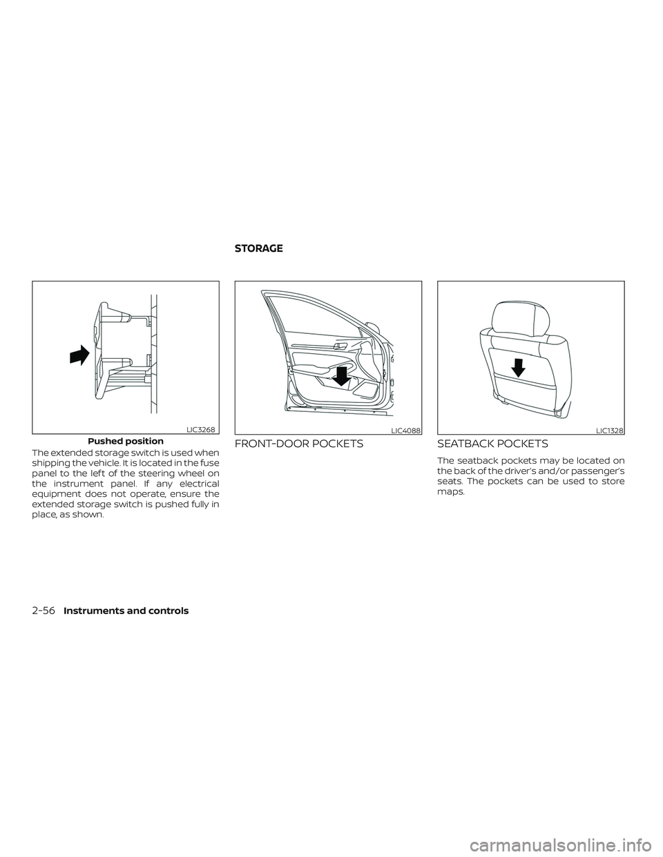
The extended storage switch is used when
shipping the vehicle. It is located in the fuse
panel to the lef t of the steering wheel on
the instrument panel. If any electrical
equipment does not operate, ensure the
extended storage switch is pushed fully in
place, as shown.FRONT-DOOR POCKETSSEATBACK POCKETS
The seatback pockets may be located on
the back of the driver’s and/or passenger’s
seats. The pockets can be used to store
maps.
Pushed position
LIC3268LIC4088LIC1328
STORAGE
2-56Instruments and controls
Page 212 of 592

MEMORY STORAGE FUNCTION
(key-link)
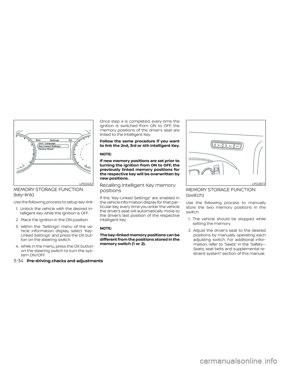
Use the following process to setup key-link:1. Unlock the vehicle with the desired In- telligent Key while the ignition is OFF.
2. Place the ignition in the ON position.
3. Within the “Settings” menu of the ve- hicle information display, select “Key-
Linked Settings” and press the OK but-
ton on the steering switch.
4. While in the menu, press the OK button on the steering switch to turn the sys-
tem ON/OFF. Once step 4 is completed, every time the
ignition is switched from ON to OFF, the
memory positions of the driver’s seat are
linked to the Intelligent Key.
Follow the same procedure if you want
to link the 2nd, 3rd or 4th Intelligent Key.
NOTE:
If new memory positions are set prior to
turning the ignition from ON to OFF, the
previously linked memory positions for
the respective key will be overwritten by
new positions.
Recalling Intelligent Key memory
positions
If the “Key-Linked Settings” are enabled in
the vehicle information display for that par-
ticular key, every time you enter the vehicle
the driver’s seat will automatically move to
the driver’s last position of the respective
Intelligent Key.
NOTE:
The key-linked memory positions can be
different from the positions stored in the
memory switch (1 or 2).
MEMORY STORAGE FUNCTION
(switch)
Use the following process to manually
store the two memory positions in the
switch:
1. The vehicle should be stopped while setting the memory.
2. Adjust the driver’s seat to the desired positions by manually operating each
adjusting switch. For additional infor-
mation, refer to “Seats” in the “Safety—
Seats, seat belts and supplemental re-
straint system” section of this manual.
LPD2432LPD2872
3-34Pre-driving checks and adjustments
Page 267 of 592

If the Easy-Fill Tire Alert is not working, use a
tire pressure gauge.
AVOIDING COLLISION AND
ROLLOVER
WARNING
Failure to operate this vehicle in a safe
and prudent manner may result in loss
of control or an accident.
Be alert and drive defensively at all times.
Obey all traffic regulations. Avoid excessive
speed, high speed cornering, or sudden
steering maneuvers, because these driving
practices could cause you to lose control of
your vehicle.
As with any vehicle, loss of control could
result in a collision with other vehicles or
objects or cause the vehicle to roll over,
particularly if the loss of control causes
the vehicle to slide sideways.
Be attentive at all times, and avoid driving
when tired. Never drive when under the in-
fluence of alcohol or drugs (including pre-
scription or over-the-counter drugs which
may cause drowsiness). Always wear your
seat belt as outlined in the “Safety – Seats,
seat belts and supplemental restraint sys- tem” section of this manual, and also in-
struct your passengers to do so.
Seat belts help reduce the risk of injury in
collisions and rollovers.
In a rollover crash,
an unbelted or improperly belted person
is significantly more likely to be injured
or killed than a person properly wearing
a seat belt.
OFF-ROAD RECOVERY
While driving, the right side or lef t side
wheels may unintentionally leave the road
surface. If this occurs, maintain control of
the vehicle by following the procedure be-
low. Please note that this procedure is only
a general guide. The vehicle must be driven
as appropriate based on the conditions of
the vehicle, road and traffic.
1. Remain calm and do not overreact.
2. Do not apply the brakes.
3. Maintain a firm grip on the steering wheel with both hands and try to hold a
straight course.
4. When appropriate, slowly release the accelerator pedal to gradually slow the
vehicle. 5. If there is nothing in the way, steer the
vehicle to follow the road while vehicle
speed is reduced. Do not attempt to
drive the vehicle back onto the road
surface until vehicle speed is reduced.
6. When it is safe to do so, gradually turn the steering wheel until both tires re-
turn to the road surface. When all tires
are on the road surface, steer the ve-
hicle to stay in the appropriate driving
lane.
∙ If you decide that it is not safe to re- turn the vehicle to the road surface
based on vehicle, road or traffic con-
ditions, gradually slow the vehicle to a
stop in a safe place off the road.
RAPID AIR PRESSURE LOSS
Rapid air pressure loss or a “blow-out” can
occur if the tire is punctured or is damaged
due to hitting a curb or pothole. Rapid air
pressure loss can also be caused by driving
on under-inflated tires.
Rapid air pressure loss can affect the han-
dling and stability of the vehicle, especially
at highway speeds.
Starting and driving5-9
Page 462 of 592

ALUMINUM ALLOY WHEELS (if so
equipped)
Wash the wheels regularly with a sponge
dampened in a mild soap solution, espe-
cially during winter months in areas where
road salt is used. If not removed, road salt
can discolor the wheels.
CAUTION
Follow the directions below to avoid
staining or discoloring the wheels:
∙ Do not use a cleaner that uses strongacid or alkali contents to clean the
wheels.
∙ Do not apply wheel cleaners to the wheels when they are hot. The wheel
temperature should be the same as
ambient temperature.
∙ Rinse the wheel to completely remove the cleaner within 15 minutes af ter
the cleaner is applied.
CHROME PARTS
Clean all chrome parts regularly with a
non-abrasive chrome polish to maintain
the finish.
TIRE DRESSINGS
NISSAN does not recommend the use of
tire dressings. Tire manufacturers apply a
coating to the tires to help reduce discolor-
ation of the rubber. If a tire dressing is ap-
plied to the tires, it may react with the coat-
ing and form a compound. This compound
may come off the tire while driving and
stain the vehicle paint.
If you choose to use a tire dressing, take the
following precautions:
∙ Use a water-based tire dressing. The coating on the tire dissolves more easily
than with an oil-based tire dressing.
∙ Apply a light coat of tire dressing to help prevent it from entering the tire
tread/grooves (where it would be diffi-
cult to remove).
∙ Wipe off excess tire dressing using a dry towel. Make sure the tire dressing is
completely removed from the tire
tread/grooves.
∙ Allow the tire dressing to dry as recom- mended by the tire dressing manufac-
turer. Occasionally remove loose dust from the
interior trim, plastic parts and seats using a
vacuum cleaner or sof t bristled brush. Wipe
the vinyl and leather (if so equipped) sur-
faces with a clean, sof t cloth dampened in
mild soap solution, then wipe clean with a
dry, sof t cloth.
Regular care and cleaning is required in
order to maintain the appearance of the
leather (if so equipped).
Before using any fabric protector, read the
manufacturer’s recommendations. Some
fabric protectors contain chemicals that
may stain or bleach the seat material.
Use a cloth dampened only with water to
clean the meter and gauge lens.
WARNING
Do not use water or acidic cleaners (hot
steam cleaners) on the seat. This can
damage the seat or occupant classifi-
cation sensor. This can also affect the
operation of the air bag system and re-
sult in serious personal injury.
CLEANING INTERIOR
7-4Appearance and care
Page 465 of 592

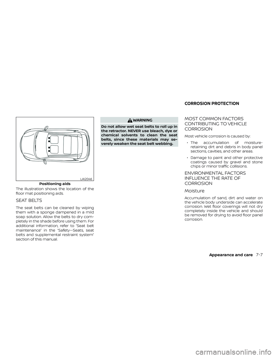
The illustration shows the location of the
floor mat positioning aids.
SEAT BELTS
The seat belts can be cleaned by wiping
them with a sponge dampened in a mild
soap solution. Allow the belts to dry com-
pletely in the shade before using them. For
additional information, refer to “Seat belt
maintenance” in the “Safety—Seats, seat
belts and supplemental restraint system”
section of this manual.
WARNING
Do not allow wet seat belts to roll up in
the retractor. NEVER use bleach, dye or
chemical solvents to clean the seat
belts, since these materials may se-
verely weaken the seat belt webbing.
MOST COMMON FACTORS
CONTRIBUTING TO VEHICLE
CORROSION
Most vehicle corrosion is caused by:∙ The accumulation of moisture- retaining dirt and debris in body panel
sections, cavities, and other areas.
∙ Damage to paint and other protective coatings caused by gravel and stone
chips or minor traffic collisions.
ENVIRONMENTAL FACTORS
INFLUENCE THE RATE OF
CORROSION
Moisture
Accumulation of sand, dirt and water on
the vehicle body underside can accelerate
corrosion. Wet floor coverings will not dry
completely inside the vehicle and should
be removed for drying to avoid floor panel
corrosion.
Positioning aids
LAI2046
CORROSION PROTECTION
Appearance and care7-7