2019 MERCEDES-BENZ METRIS tow
[x] Cancel search: towPage 294 of 318

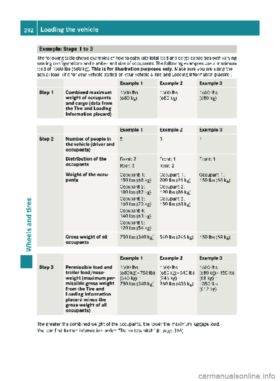
Example: Steps 1 to 3
The following table shows examples of how to calculate total load and cargo capacities with varyingseating configurations and number and size of occupants. The following examples use a maximum
load of 1500 lbs (680 kg). This is for illustration purposes only. Make sure you are using the
actual load limit for your vehicle stated on your vehicle's Tire and Loading Information placard .
Example 1Example 2Example 3
Step 1Combined maximum
weight of occupants
and cargo (data from
the Tire and Loading
Information placard)1500 lbs
(680 kg)1500 lbs
(680 kg)1500 lbs
(680 kg)
Example 1Example 2Example 3
Step 2Number of people in
the vehicle (driver and
occupants)531
Distribution of the
occupantsFront: 2
Rear: 3Front: 1
Rear: 2Front: 1
Weight of the occu-
pantsOccupant 1:
150 lbs (68 kg)
Occupant 2:
180 lbs (82 kg)
Occupant 3:
160 lbs (73 kg)
Occupant 4:
140 lbs (63 kg)
Occupant 5:
120 lbs (54 kg)Occupant 1:
200 lbs (91 kg)
Occupant 2:
190 lbs (86 kg)
Occupant 3:
150 lbs (68 kg)Occupant 1:
150 lbs (68 kg)
Gross weight of all
occupants750 lbs (340 kg)540 lbs (245 kg)150 lbs (68 kg)
Example 1Example 2Example 3
Step 3Permissible load and
trailer load/nose-
weight (maximum per-
missible gross weight
from the Tire and
Loading Information
placard minus the
gross weight of all
occupants)1500 lbs
(680 kg) Ò750 lbs
(340 kg) =
750 lbs (340 kg)1500 lbs
(680 kg) Ò540 lbs
(245 kg) =
960 lbs (435 kg)1500 lbs
(680 kg) Ò150 lbs
(68 kg) =
1350 lbs
(612 kg)
The greater the combined weight of the occupants, the lower the maximum luggage load.
You can find further information under: "Trailer tow hitch" (
Ypage 316).
292Loading the vehicle
Wheels and tires
Page 300 of 318

TIN (Tire Identification Number)
A unique identification number which can be
used by a tire manufacturer to identify tires, for
example for a product recall, and thus identify
the purchasers. The TIN is composed of the
manufacturer identification code, tire size, tire
model code and manufacturing date.
Load bearing index
The load bearing index (also load index) is a code
that contains the maximum load bearing capa-
city of a tire.
Traction
Traction is the result of friction between the tires
and the road surface.
TWR (permissible trailer drawbar load)
The TWR is the maximum permissible weight
that may act on the ball coupling of the trailer
tow hitch.
Wear indicator
Narrow bars (tread wear bars) that are distrib-
uted over the tire tread. If the tire tread is level
with the bars, the wear limit of áin (1.6 mm)
has been reached.
Distribution of the vehicle occupants
The distribution of vehicle occupants over des-
ignated seat positions in a vehicle.
Maximum permissible payload weight
Nominal load and goods/luggage load plus
68 kg (150 lb s)multiplied by the number of
seats in the vehicle.
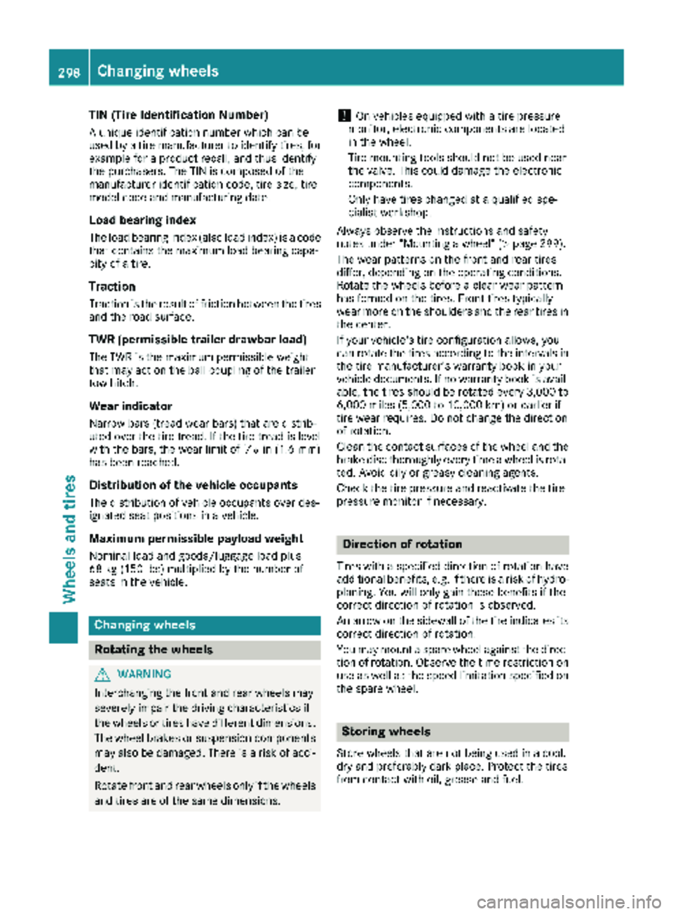
Changing wheels
Rotating the wheels
GWARNING
Interchanging the front and rear wheels may
severely impair the driving characteristics if
the wheels or tires have different dimensions. The wheel brakes or suspension components
may also be damaged. There is a risk of acci-
dent.
Rotate front and rear wheels only if the wheels and tires are of the same dimensions.
!On vehicles equipped with a tire pressure
monitor, electronic components are located
in the wheel.
Tire-mounting tools should not be used near
the valve. This could damage the electronic
components.
Only have tires changed at a qualified spe-
cialist workshop.
Always observe the instructions and safety
notes under "Mounting a wheel" (
Ypage 299).
The wear patterns on the front and rear tires
differ, depending on the operating conditions.
Rotate the wheels before a clear wear pattern
has formed on the tires. Front tires typically
wear more on the shoulders and the rear tires in the center.
If your vehicle's tire configuration allows, you
can rotate the tires according to the intervals in
the tire manufacturer's warranty book in your
vehicle documents. If no warranty book is avail-
able, the tires should be rotated every 3,000 to
6,000 miles (5,000 to 10,000 km) or earlier if
tire wear requires. Do not change the direction
of rotation.
Clean the contact surfaces of the wheel and the
brake disc thoroughly every time a wheel is rota-
ted. Avoid oily or greasy cleaning agents.
Check the tire pressure and reactivate the tire
pressure monitor if necessary.
Direction of rotation
Tires with a specified direction of rotation have
additional benefits, e.g. if there is a risk of hydro-
planing. You will only gain these benefits if the
correct direction of rotation is observed.
An arrow on the sidewall of the tire indicates its
correct direction of rotation.
You may mount a spare wheel against the direc-tion of rotation. Observe the time restriction on
use as well as the speed limitation specified on
the spare wheel.
Storing wheels
Store wheels that are not being used in a cool,
dry and preferably dark place. Protect the tires
from contact with oil, grease and fuel.
298Changing wheels
Wheels and tires
Page 303 of 318

Only use wheel bolts that have been designed
for the wheel and the vehicle. For safety rea-
sons, Mercedes-Benz recommends that you
only use wheel bolts which have been approved
for Mercedes-Benz vehicles and the respective
wheel.
!On vehicles equipped with a tire pressure
monitor, electronic components are located
in the wheel.
Tire-mounting tools should not be used near
the valve. This could damage the electronic
components.
Only have tires changed at a qualified spe-
cialist workshop.
XClean the wheel and wheel hub contact sur-
faces.
XSlide the new wheel onto the wheel hub and
push it on.
XScrew in the wheel bolts and tighten them
lightly.
Lowering the vehicle
GWARNING
The wheels could work loose if the wheel nuts and bolts are not tightened to the specified
tightening torque. There is a risk of accident.
Have the tightening torque immediately
checked at a qualified specialist workshop
after a wheel is changed.
:—AWheel bolts
XPlace the adapter and the ratchet on the hex-
agon head nut of the jack such that the let-
tering AB/DOWN is visible.
XTurn the ratchet in the AB/DOWNdirection
until the vehicle is once again standing firmly
on the ground.
XPut the jack aside.
XTighten the wheel bolts evenly in a crosswise
pattern in the sequence indicated (: toA).
Tighten the wheel bolts to the following tight-
ening torques:
RSteel wheel 147 lb-ft(200 Nm)
RAlloy wheel 133 lb-ft(180 Nm)
XTurn the jack back to its out-of-use position.
XStow the jack and the rest of the tire-change
tool kit in the vehicle again.
XWheel with hub cap: position the opening for
the tire valve in the hub cap over the tire valve.
XPush the edge of the hub cap with both hands
against the wheel until it clicks into place.
Make sure the hub cap retaining catches
engage on the steel wheel.
XIf included in the vehicle equipment, secure
the faulty wheel in the spare wheel bracket
(
Ypage 303). Otherwise, transport the faulty
wheel in the cargo compartment.
XCheck the tire pressure of the newly mounted
wheel and adjust it if necessary.
Observe the recommended tire pressure
(
Ypage 282).
Vehicles with the tire pressure monitor sys-
tem: all mounted wheels must be equipped
with functioning sensors.
XRetighten the wheel bolts or wheel nuts to the
specified tightening torque after the vehicle
has been driven for 30 miles (50 km).
Changing wheels301
Wheels and tires
Z
Page 306 of 318

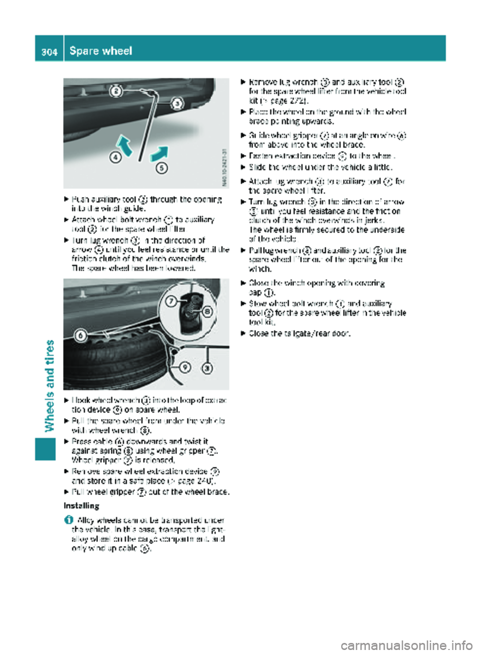
XPush auxiliary tool;through the opening
into the winch guide.
XAttach wheel bolt wrench =to auxiliary
tool ;for the spare wheel lifter.
XTurn lug wrench =in the direction of
arrow ?until you feel resistance or until the
friction clutch of the winch overwinds.
The spare wheel has been lowered.
XHook wheel wrench =into the loop of extrac-
tion device Eon spare wheel.
XPull the spare wheel from under the vehicle
with wheel wrench =.
XPress cableBdownwards and twist it
against spring Dusing wheel gripper C.
Wheel gripper Cis released.
XRemove spare wheel extraction device E
and store it in a safe place (Ypage 240).
XPull wheel gripper Cout of the wheel brace.
Installing
iAlloy wheels cannot be transported under
the vehicle. In this case, transport the light-
alloy wheel on the cargo compartment, and
only wind up cable B.
XRemove lug wrench =and auxiliary tool ;
for the spare wheel lifter from the vehicle tool
kit (
Ypage 272).
XPlace the wheel on the ground with the wheel brace pointing upwards.
XGuide wheel gripper Cat an angle on wire B
from above into the wheel brace.
XFasten extraction device Eto the wheel.
XSlide the wheel under the vehicle a little.
XAttach lug wrench =to auxiliary tool ;for
the spare wheel lifter.
XTurn lug wrench =in the direction of arrow
A until you feel resistance and the friction
clutch of the winch overwinds in jerks.
The wheel is firmly secured to the underside
of the vehicle.
XPull lug wrench =and auxiliary tool ;for the
spare wheel lifter out of the opening for the
winch.
XClose the winch opening with covering
cap :.
XStow wheel bolt wrench =and auxiliary
tool ;for the spare wheel lifter in the vehicle
tool kit.
XClose the tailgate/rear door.
304Spare wheel
Wheels and tires
Page 310 of 318

iE10 fuel contains an admixture of up to 10%
bioethanol. Your vehicle is E10 compatible.
You can refuel your vehicle with E10 fuel.
iUsually you will find information about the
fuel grade on the filling pump. If there is no
identification on the filling pump, consult a
gas station attendant.
If the recommended fuel is not available, you
may as a one-off measure use regular unleaded
gasoline with an octane rating of 87 AKI/
91 RON. Be aware that your vehicle is not cer-
tified with regular unleaded gasoline with an
octane rating of 87 AKI/91 RON and that usage
of this fuel may reduce the engine's output and
increase fuel consumption. Avoid driving at full
throttle and sudden acceleration. Never refuel
using gasoline with a lower AKI/RON rating.
iIn some countries, the available gasoline
may not be sufficiently low in sulfur. This fuel can temporarily produce unpleasant odors,
especially on short journeys. The odors are
reduced as soon as sulfur-free fuel (sulfur
content < 10 ppm) is used again for refueling.
For more information about refueling
(
Ypage 134).
Fuel additives
!Operating the engine with subsequently
added fuel additives can cause engine dam-
age. Do not mix fuel additives with fuel. This
does not include additives for the removal and
prevention of deposits. Gasoline can only be
mixed with additives recommended by
Mercedes-Benz. Follow the instructions in the
product description. You can find further
information on recommended additives in any
Mercedes-Benz Commercial Van Center.
Mercedes-Benz recommends using brand-name
fuels with additives.
If you use fuels without these additives for a long
period of time, deposits can form. This primarily
forms on the inlet valve and in the combustion
chamber.
In some countries, the available fuel grade may
be inadequate. Residue could build up in the fuel
injection system as a result. In this case, in con-
sultation with a Mercedes-Benz Commercial
Van Center, the fuel should be mixed with the
cleaning additive recommended by Mercedes-
Benz. You must observe the notes and mixing
ratios indicated on the container. Do not add other fuel additives to the fuel. This
results in unnecessary costs and can damage
the engine.
Information on fuel consumption
HEnvironmental note
CO
2(carbon dioxide) is the gas which scien-
tists believe to be principally responsible for
global warming (the greenhouse effect). Your
vehicle's CO
2emissions are directly related to
fuel consumption and therefore depend on:
Refficient use of the fuel by the engine
Rdriving style
Rother non-technical factors, such as envi-
ronmental influences, road conditions or
traffic flow
You can minimize your vehicle's CO
2emis-
sions by driving carefully and having it serv-
iced regularly.
Only for certain countries: the respective cur-
rent consumption and emission values of your
vehicle can be found in the COC papers (EC
CERTIFICATE OF CONFORMITY). These docu-
ments are supplied when the vehicle is deliv-
ered.
Consumption figures were found in the currently
valid respective version:
Rfor vehicles with exhaust gas standard Euro 6
as per directive (EC) no. 715/2007
Rfor vehicles with exhaust gas standard EURO
VI as per directive (EC) no. 595/2009
Fuel consumption depends on:
Rthe vehicle version
Rthe style of driving
Rthe operating conditions
Rthe type or quality of the fuel used
The vehicle will use mor e fu
el than usual in the
following situations:
Rat very low outside temperatures
Rin city traffic
Rduring short journeys
Ron mountainous terrain
Rwhen towing a trailer
Observe the advice in the "Protection of the
environment" section to keep fuel consumption low (
Ypage 29).
308Service products and capacities
Technical data
Page 317 of 318

Guide/load rails
The maximum tensile load for the cargo tie-
down points on a guide/load rail is:
Cargo tie-down
pointPermissible nomi-nal tensile load
Guide rail786.5 lbf
(350 daN)
Load rails on cargo
compartment floor1124.0 lbf (500 daN)
Load rail on sidewall225.0 lbf
(100 daN)
The values specified apply only to loads placed
on the cargo compartment floor if:
Rthe load is secured to two cargo tie-down
points on the rail and
Rthe distance to the nearest load-securing
point on the same rail is approximately 3 ft
(1 m)
Maximum roof load
GWARNING
If you use openings in the bodywork or
detachable parts as steps, you could:
Rslip and/or fall
Rdamage the vehicle and cause yourself to
fall.
There is a risk of injury.
Always use secure climbing aids, e.g. a suita-
ble ladder.
!Do not use the lower sliding door guide (car-
riage) as a step. Otherwise, you could damage
the paneling and/or the sliding door mecha-
nism.
GWARNING
When you load the roof, the center of gravity
of the vehicle rises and the driving character-
istics change. If you exceed the maximum roof
load, the driving characteristics, as well as
steering and braking, will be greatly impaired.
There is a risk of an accident.
Never exceed the maximum roof load and
adjust your driving style.
!The weight of any load carried on the roof,
including the roof carrier, must not exceed
the maximum permissible roof load.
The roof carrier supports must be mounted at
equal distances.
Install rail carriers in front of and behind the
middle prop.
!For safety reasons, Mercedes-Benz recom-
mends that you only use roof carrier systems
which have been tested and approved for
Mercedes-Benz vehicles. This will help to
avoid damage.
Maximum roof load330 lbs (150 kg)
with at least three
pairs of support
points
The data is valid for a load distributed evenly
over the entire roof area.
Reduce the load on shorter roof carriers pro-
portionately. The maximum load per pair of roof
carrier supports is 110 lbs (50 kg). The maxi-
mum load of a rail carrier bar is 220 lbs (100 kg).
Loading guidelines and other information con-
cerning load distribution and load securing can
be found in the "Transporting" section
(
Ypage 244).
Trailer tow hitch
General notes
Mercedes-Benz recommends having a trailer
tow hitch retrofitted at an authorized Mercedes-
Benz Van Dealer.
Use only a trailer tow hitch that has been tested
and approved specially for your vehicle by the
distributor named on the inside of the front
cover. Only use a ball coupling for your Metris
trailer tow hitch if it has been approved for your
vehicle. You can also find information on the
permitted dimensions of the ball coupling on the
identification plate of the trailer tow hitch.
You can obtain advice from a qualified specialist
workshop. Also observe the information on tow-
ing a trailer in the "Driving and parking" section
(
Ypage 165).
Vehicle data315
Technical data
Z
Page 318 of 318

Trailer loads
Make sure that you adhere to the local legal
requirements for trailer loads.
The permissible weights and loads which cannot
be exceeded can also be found:
Rin your vehicle documents and
Ron the identification plates of the trailer tow
hitch, the trailer and the vehicle
(
Ypage 305)
You will find the basic values approved by the
manufacturer in the following table. If the values
differ, the lowest value applies.
Make sure that you adhere to the weight restric-
tions by having the weight checked on a cali-
brated weighbridge.
Permissible gross
weight GVWR6724 lbs (3050 kg)
Gross front axle
load GAWR (FA)3417 lbs (1550 kg)
Gross rear axle load
GAWR (RA)3417 lbs (1550 kg)
Maximum permissi-
ble gross weight of
vehicle/trailer
combination
2
GCWR
11684 lbs (5300 kg)
Trailer load,
braked3GTW
5000 lbs (2268 kg)
Maximum permissi-
ble nose weight
TWR500 lbs (227 kg)
2Maximum permissible gross weight of the vehicle and trailer.3Maximum permissible gross trailer weight, for trailers with a separate functional braking system.
316Vehicle data
Technical data