2019 MERCEDES-BENZ GLS SUV check engine
[x] Cancel search: check enginePage 346 of 398
G
WARNING
A discharged battery can freeze at temperatures below freezing point. When jump-starting the
vehicle or charging the battery, gases can escape from the battery. There is a risk of an explosion.
Allow the frozen battery to thaw out before charging it or jump-starting.
! Vehicles with a gasoline engine:
avoid repeated and lengthy starting attempts. Otherwise, the
catalytic converter could be damaged by non-combusted fuel.
If the indicator/warning lamps do not light up at low temperatures, it is very likely that the dis-
charged battery has frozen. In this case you may neither jump-start the vehicle nor charge the
battery. The service life of a thawed-out battery may be shorter. The starting characteristics can be
impaired, particularly at low temperatures. Have the thawed-out battery checked at a qualified
specialist workshop.
Do not start the vehicle using a rapid charging device. If your vehicle's battery is discharged, the
engine can be jump-started from another vehicle or from a donor battery using jumper cables.
Observe the following points:
R The battery is not accessible in all vehicles. If the other vehicle's battery is not accessible, jump-
start the vehicle using a donor battery or a jump-starting device.
R Vehicles with a gasoline engine: only jump-start the vehicle when the engine and exhaust
system are cold.
R Do not start the engine if the battery is frozen. Let the battery thaw first.
R Only jump-start from batteries with a 12 V voltage rating.
R Only use jumper cables which have a sufficient cross-section and insulated terminal clamps.
R If the battery is fully discharged, leave the battery that is being used to jump-start connected for
a few minutes before attempting to start. This charges the battery slightly.
R Make sure that the two vehicles do not touch.
Make sure that:
R The jumper cables are not damaged.
R Bare parts of the terminal clamp do not come into contact with other metal parts while the jumper
cables are connected to the battery.
R The jumper cables cannot come into contact with parts that can move when the engine is running,
such as the V-belt pulley or the fan.
X Secure the vehicle by applying the electric parking brake.
X Shift the transmission to position 005D.
X Make sure that the ignition is switched off. All indicator lamps in the instrument cluster must be
off. When using the SmartKey, turn the SmartKey to position 0092in the ignition lock and remove it
(Y page 140).
X Switch off all electrical consumers, e.g. rear window defroster, lighting, etc.
X Open the hood.
i Right-hand-drive vehicle:
the jump-starting connection points may be located on the other
side of the vehicle. 344
Jump-startingBreakdown assistance
Page 347 of 398
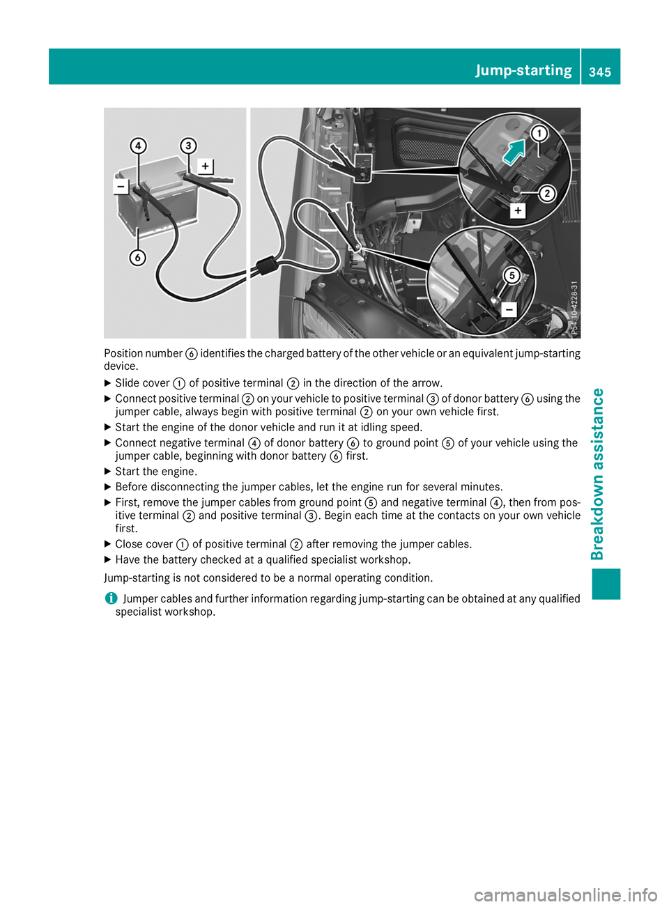
Position number
0084identifies the charged battery of the other vehicle or an equivalent jump-starting
device.
X Slide cover 0043of positive terminal 0044in the direction of the arrow.
X Connect positive terminal 0044on your vehicle to positive terminal 0087of donor battery 0084using the
jumper cable, always begin with positive terminal 0044on your own vehicle first.
X Start the engine of the donor vehicle and run it at idling speed.
X Connect negative terminal 0085of donor battery 0084to ground point 0083of your vehicle using the
jumper cable, beginning with donor battery 0084first.
X Start the engine.
X Before disconnecting the jumper cables, let the engine run for several minutes.
X First, remove the jumper cables from ground point 0083and negative terminal 0085, then from pos-
itive terminal 0044and positive terminal 0087. Begin each time at the contacts on your own vehicle
first.
X Close cover 0043of positive terminal 0044after removing the jumper cables.
X Have the battery checked at a qualified specialist workshop.
Jump-starting is not considered to be a normal operating condition.
i Jumper cables and further information regarding jump-starting can be obtained at any qualified
specialist workshop. Jump-starting
345Breakdown assistance Z
Page 352 of 398
X
Remove the SmartKey from the ignition lock.
Or, on vehicles with KEYLESS-GO start function
or KEYLESS‑GO:
X Open the driver's door.
The vehicle electronics are now in key posi-
tion 0092. This is the same as the SmartKey
having been removed.
The driver’s door can be closed again.
X Secure the vehicle against rolling away
(Y page 158).
All indicator lamps in the instrument cluster
must be off.
The fuses are located in various fuse boxes:
R Fuse box on the front-passenger side of the
dashboard
R Fuse box in the engine compartment on the
right-hand side of the vehicle, when viewed in
the direction of travel
R Fuse box under the rear bench seat Dashboard fuse box
! Do not use a pointed object such as a screw-
driver to open the cover in the dashboard. You
could damage the dashboard or the cover.
Mercedes-Benz recommends that you have this work performed at a qualified specialist work-
shop, e.g. at an authorized Mercedes-Benz Cen-
ter. X
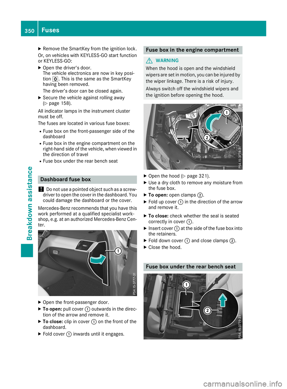
Open the front-passenger door.
X To open: pull cover 0043outwards in the direc-
tion of the arrow and remove it.
X To close: clip in cover 0043on the front of the
dashboard.
X Fold cover 0043inwards until it engages. Fuse box in the engine compartment
G
WARNING
When the hood is open and the windshield
wipers are set in motion, you can be injured by the wiper linkage. There is a risk of injury.
Always switch off the windshield wipers and
the ignition before opening the hood. X
Open the hood (Y page 321).
X Use a dry cloth to remove any moisture from
the fuse box.
X To open: open clamps 0044.
X Fold up cover 0043in the direction of the arrow
and remove it.
X To close: check whether the seal is seated
correctly in cover 0043.
X Insert cover 0043at the side of the fuse box into
the retainers.
X Fold down cover 0043and close clamps 0044.
X Close the hood. Fuse box under the rear bench seat350
FusesBreakdown assistance
Page 375 of 398
ponents may also be damaged. There is a risk
of an accident.
Rotate front and rear wheels only if the wheels
and tires are of the same dimensions.
! On vehicles equipped with a tire pressure
monitor, electronic components are located
in the wheel.
Tire-mounting tools should not be used near
the valve. This could damage the electronic
components.
Only have tires changed at a qualified spe-
cialist workshop.
Always observe the instructions and safety
notes in the "Mounting a wheel" section
(Y page 373).
The wear patterns on the front and rear tires
differ, depending on the operating conditions.
Rotate the wheels before a clear wear pattern
has formed on the tires. Front tires typically
wear more on the shoulders and the rear tires in
the center.
On vehicles that have the same size front and
rear wheels, you can rotate the wheels accord-
ing to the intervals in the tire manufacturer's
warranty book in your vehicle documents. If no
warranty book is available, the tires should be
rotated every 3,000 to 6,000 miles (5,000 to
10,000 km). Depending on tire wear, this may
be required earlier. Do not change the direction
of wheel rotation.
Clean the contact surfaces of the wheel and the brake disc thoroughly every time a wheel is rota-
ted. Check the tire pressure and, if necessary,
restart the tire pressure loss warning system or
the tire pressure monitor (Y page 359).Direction of rotation
Tires with a specified direction of rotation have
additional benefits, e.g. if there is a risk of hydro-
planing. These advantages can only be gained if the tires are installed corresponding to the
direction of rotation.
An arrow on the sidewall of the tire indicates its
correct direction of rotation. Storing wheels
Store wheels that are not being used in a cool,
dry and preferably dark place. Protect the tires
from oil, grease, gasoline and diesel. Mounting a wheel
Preparing the vehicle X
Vehicle with emergency spare wheel:
when mounting the emergency spare wheel in
the event of a flat tire, follow the additional
notes on vehicle preparation under "Flat tire" (Y page 335).
X Stop the vehicle on solid, non-slippery and
level ground.
X Apply the electric parking brake manually.
X Bring the front wheels into the straight-ahead
position.
X Vehicles with automatic transmission:
shift the transmission to position
005D.
X Vehicles with the AIRMATIC package:
make sure that the normal vehicle level is
selected (Y page 187).
X Vehicles with the Off-Road Engineering
package:
make sure that the normal level is
selected (Y page 180).
X Switch off the engine.
X Vehicles without KEYLESS-GO: remove the
SmartKey from the ignition lock.
X Vehicles with KEYLESS-GO: open the driv-
er's door.
The vehicle electronics are now in position
0092. This means no SmartKey is in the ignition lock.
X Vehicles with KEYLESS-GO: remove the
Start/Stop button from the ignition lock
(Y page 140).
X If included in the vehicle equipment, remove
the tire-change tool kit from the vehicle.
X Safeguard the vehicle against rolling away.
i Apart from certain country-specific varia-
tions, vehicles are not equipped with a tire-
change tool kit. For more information on
which tools are required to perform a wheel
change on your vehicle, consult a qualified
specialist workshop. Changing a wheel
373Wheels and tires Z
Page 390 of 398
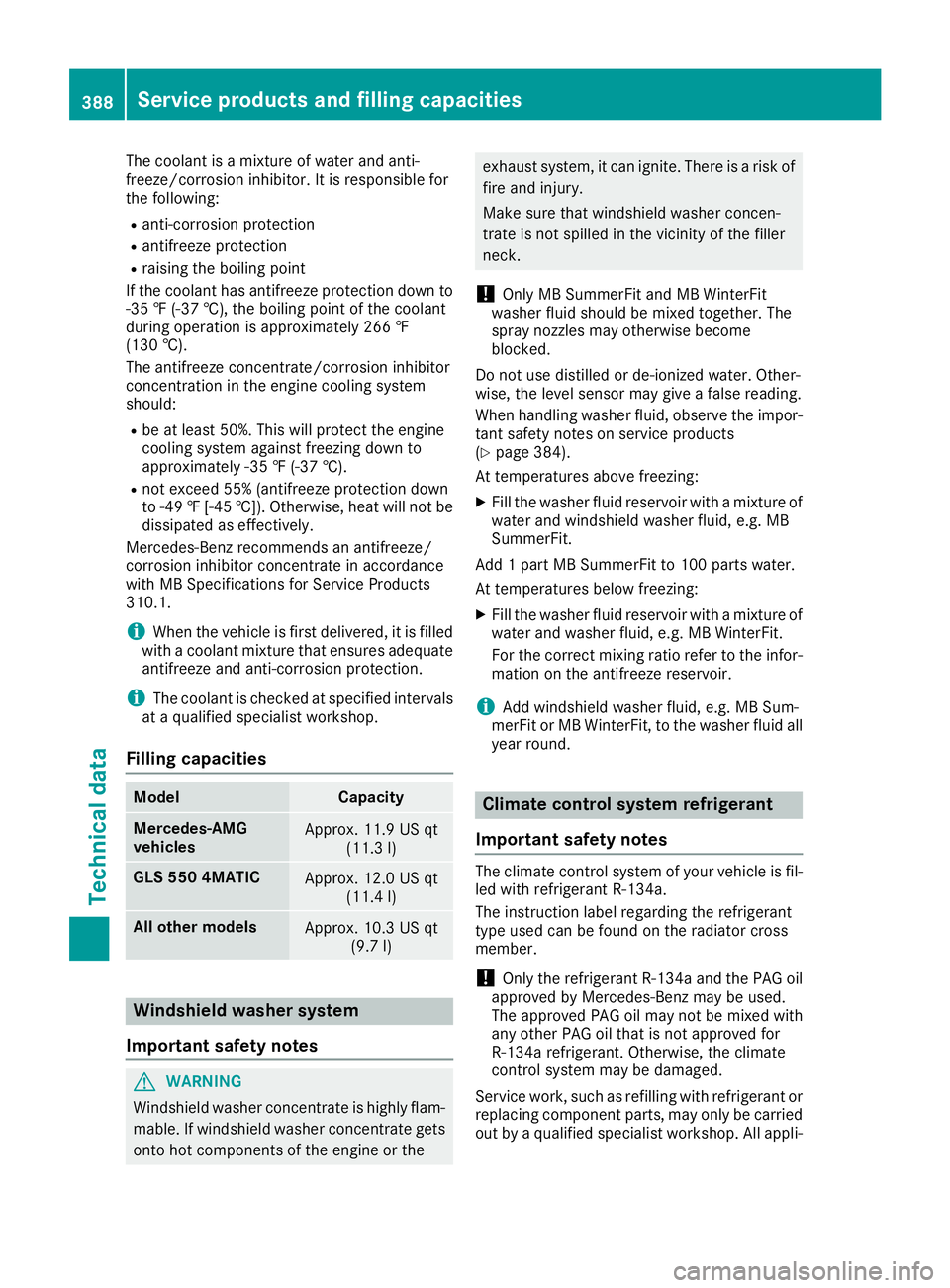
The coolant is a mixture of water and anti-
freeze/corrosion inhibitor. It is responsible for
the following:
R anti-corrosion protection
R antifreeze protection
R raising the boiling point
If the coolant has antifreeze protection down to -35 ‡ (-37 †), the boiling point of the coolant
during operation is approximately 266 ‡
(130 †).
The antifreeze concentrate/corrosion inhibitor
concentration in the engine cooling system
should:
R be at least 50%. This will protect the engine
cooling system against freezing down to
approximately -35 ‡ (-37 †).
R not exceed 55% (antifreeze protection down
to -49 ‡[-45 †]). Otherwise, heat will not be
dissipated as effectively.
Mercedes-Benz recommends an antifreeze/
corrosion inhibitor concentrate in accordance
with MB Specifications for Service Products
310.1.
i When the vehicle is first delivered, it is filled
with a coolant mixture that ensures adequate
antifreeze and anti-corrosion protection.
i The coolant is checked at specified intervals
at a qualified specialist workshop.
Filling capacities Model Capacity
Mercedes
‑AMG
vehicles Approx. 11.9 US qt
(11.3 l) GLS 550 4MATIC
Approx. 12.0 US qt
(11.4 l) All other models
Approx. 10.3 US qt
(9.7 l) Windshield washer system
Important safety notes G
WARNING
Windshield washer concentrate is highly flam- mable. If windshield washer concentrate getsonto hot components of the engine or the exhaust system, it can ignite. There is a risk of
fire and injury.
Make sure that windshield washer concen-
trate is not spilled in the vicinity of the filler
neck.
! Only MB SummerFit and MB WinterFit
washer fluid should be mixed together. The
spray nozzles may otherwise become
blocked.
Do not use distilled or de-ionized water. Other-
wise, the level sensor may give a false reading.
When handling washer fluid, observe the impor- tant safety notes on service products
(Y page 384).
At temperatures above freezing:
X Fill the washer fluid reservoir with a mixture of
water and windshield washer fluid, e.g. MB
SummerFit.
Add 1 part MB SummerFit to 100 parts water.
At temperatures below freezing:
X Fill the washer fluid reservoir with a mixture of
water and washer fluid, e.g. MB WinterFit.
For the correct mixing ratio refer to the infor- mation on the antifreeze reservoir.
i Add windshield washer fluid, e.g. MB Sum-
merFit or MB WinterFit, to the washer fluid all
year round. Climate control syste
m refrigerant
Important safety notes The climate control system of your vehicle is fil-
led with refrigerant R‑134a.
The instruction label regarding the refrigerant
type used can be found on the radiator cross
member.
! Only the refrigerant R‑134a and the PAG oil
approved by Mercedes-Benz may be used.
The approved PAG oil may not be mixed with
any other PAG oil that is not approved for
R-134a refrigerant. Otherwise, the climate
control system may be damaged.
Service work, such as refilling with refrigerant or
replacing component parts, may only be carried out by a qualified specialist workshop. All appli- 388
Service products and filling capacitiesTechni
cal data