2019 MERCEDES-BENZ GLS Ball mount
[x] Cancel search: Ball mountPage 24 of 398
Display message ............................ 268
Distribution of the vehicle occu-
pants (definition) ............................ 372
DOT (Department of Transporta-
tion) (definition) ............................. 370
DOT, Tire Identification Number
(TIN) ............................................... 370
GAWR (Gross Axle Weight Rating)
(definition) .................................... .371
GTW (Gross Trailer Weight) (defi-
nition) ............................................ 371
GVW (Gross Vehicle Weight) (def-
inition) .......................................... .371
GVWR (Gross Vehicle Weight Rat-
ing) (definition) .............................. 371
Important safety notes .................. 352
Increased vehicle weight due to
optional equipment (definition) ...... 371
Information on driving .................... 352
Kilopascal (kPa) (definition) ........... 371
Labeling (overview )........................ 367
Load bearing index (definition) ...... 372
Load index ..................................... 369
Load index (definition) ................... 371
M+S tire s....................................... 354
Maximum load on a tire (defini-
tion) ............................................... 371
Maximum loaded vehicle weight
(definition) ..................................... 371
Maximum permissible tire pres-
sure (definition) ............................. 371
Maximum tire load ......................... 369
Maximum tire load (definition) ....... 371
MOExtended tire s.......................... 353
Optional equipment weight (defi-
nition) ............................................ 372
PSI (pounds per square inch) (def-
inition) ........................................... 372
Replacing ....................................... 372
Service life ..................................... 353
Sidewall (definition) ....................... 372
Snow chains .................................. 354
Speed rating (definition) ................ 371
Storing ........................................... 373
Structure and characteristics
(definition) ..................................... 370
Summer tires in winter .................. 354
Temperature .................................. 366 TIN (Tire Identification Number)
(definition) ..................................... 372
Tire bead (definition) ...................... 372
Tire pressure (definition) ................ 372
Tire pressures (recommended) ...... 371
Tire size (data) ............................... 377
Tire size designation, load-bearing
capacity, speed rating .................... 367
Tire tread ....................................... 353
Tire tread (definition) ..................... 372
Total load limit (definition) ............. 372
Traction ......................................... 366
Traction (definition) ....................... 372
Tread wear ..................................... 366
TWR (permissible trailer drawbar
noseweight) (definition) ................. 372
Uniform Tire Quality Grading
Standards ...................................... 366
Uniform Tire Quality Grading
Standards (definition) .................... 370
Wear indicator (definition) ............. 372
Wheel and tire combination ........... 377
Wheel rim (definition) .................... 371
see Flat tire
Tool
see Vehicle tool kit
Top Tether ............................................ 63
Tow-starting
Emergency engine starting ............ 349
Important safety notes .................. 346
Towing
Permitted towing methods ............ 347
Towing a trailer
Axle load, permissibl e.................... 392
Cleaning the trailer tow hitch ......... 331
Coupling up a traile r...................... 224
Decoupling a trailer ....................... 226
Driving tip s.................................... 222
Important safety notes .................. 221
Installing the ball coupling ............. 223
Lights display message .................. 257
Mounting dimensions .................... 392
Parking Assist PARKTRONIC .......... 189
Power supply ................................. 227
Pulling away with a traile r.............. 143
Removing the ball coupling ............ 226
Trailer load s................................... 392 22
Index
Page 225 of 398
R
Maintain a greater distance from the vehicle
in front than when driving without a trailer.
R Avoid braking abruptly. If possible, brake gen-
tly at first to allow the trailer to run on. Then,
increase the braking force rapidly.
R The values given for gradient-climbing capa-
bilities from a standstill refer to sea level.
When driving in mountainous areas, note that
the power output of the engine and, conse-
quently, the vehicle's gradient-climbing capa- bility, decreases with increasing altitude. Installing the ball coupling
G
WARNING
If the ball coupling is not correctly installed
and secured, it can come loose during the
journey and endanger other road users. There is a risk of an accident and injury.
Always install and secure the ball coupling as
described. Before every journey, ensure that
the ball coupling is secured with the bolt and
the corresponding spring cotter. G
WARNING
If the ball coupling is not installed correctly or not secured with the bolt provided and the
corresponding spring cotter, the trailer may
come loose. There is a risk of an accident.
Always install and secure the ball coupling as
described. Before every journey, ensure that
the ball coupling is secured with the bolt and
the corresponding spring cotter. G
WARNING
If the ball coupling is not installed and secured
correctly the trailer may come loose. There is
a risk of an accident.
Install and secure the ball coupling as descri-
bed in the ball coupling installation instruc-
tions. Make sure that the ball coupling is
installed and secured correctly before every
journey. X
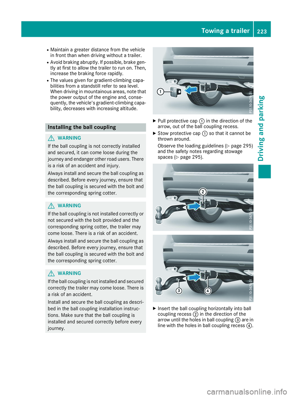
Pull protective cap 0043in the direction of the
arrow, out of the ball coupling recess.
X Stow protective cap 0043so that it cannot be
thrown around.
Observe the loading guidelines (Y page 295)
and the safety notes regarding stowage
spaces (Y page 295). X
Insert the ball coupling horizontally into ball
coupling recess 0044in the direction of the
arrow until the holes in ball coupling 0087are in
line with the holes in ball coupling recess 0085. Towing a trailer
223Driving and parking Z
Page 226 of 398
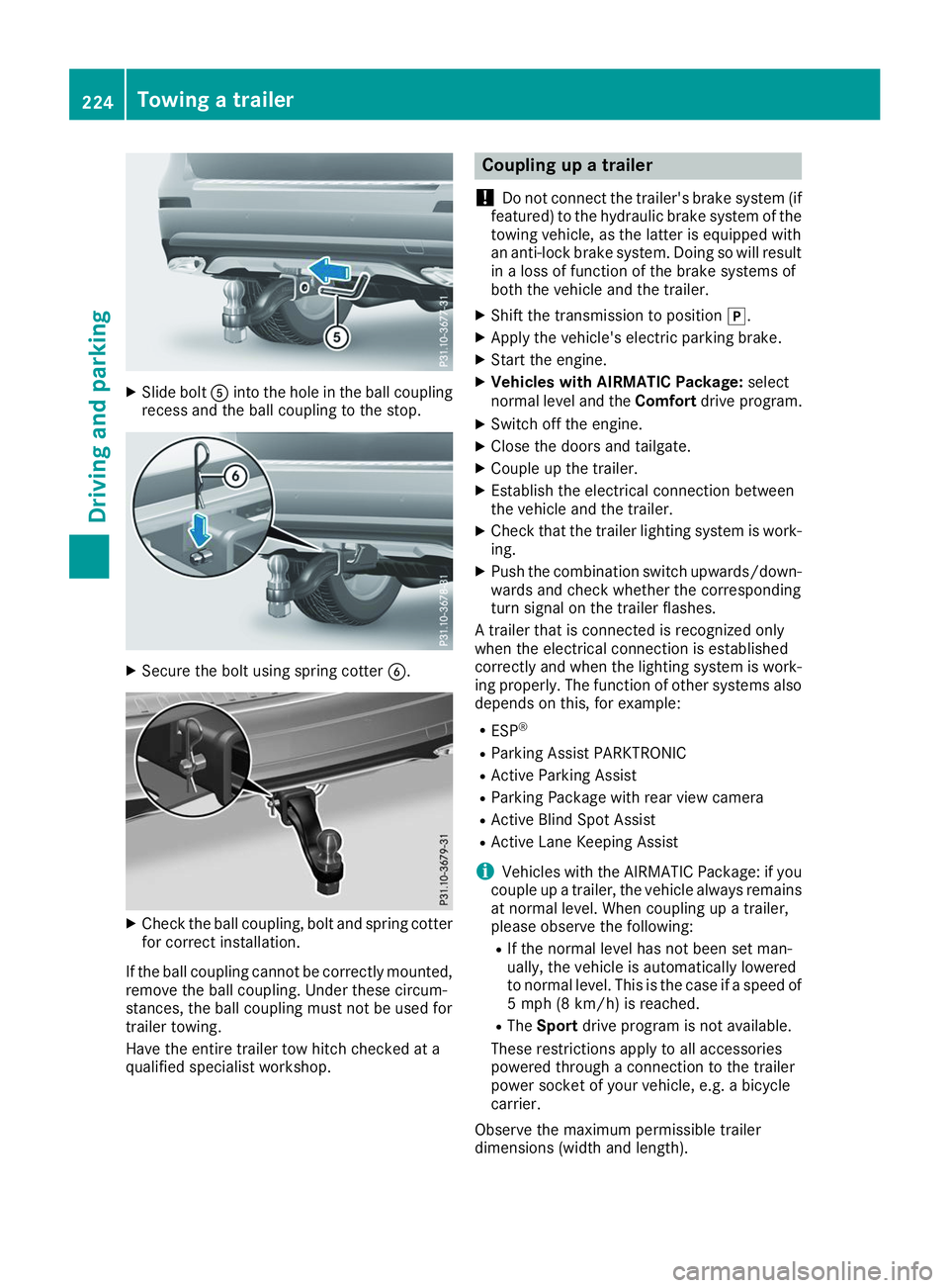
X
Slide bolt 0083into the hole in the ball coupling
recess and the ball coupling to the stop. X
Secure the bolt using spring cotter 0084.X
Check the ball coupling, bolt and spring cotter
for correct installation.
If the ball coupling cannot be correctly mounted,
remove the ball coupling. Under these circum-
stances, the ball coupling must not be used for
trailer towing.
Have the entire trailer tow hitch checked at a
qualified specialist workshop. Coupling up a trailer
! Do not connect the trailer's brake system (if
featured) to the hydraulic brake system of the towing vehicle, as the latter is equipped with
an anti-lock brake system. Doing so will result
in a loss of function of the brake systems of
both the vehicle and the trailer.
X Shift the transmission to position 005D.
X Apply the vehicle's electric parking brake.
X Start the engine.
X Vehicles with AIRMATIC Package: select
normal level and the Comfortdrive program.
X Switch off the engine.
X Close the doors and tailgate.
X Couple up the trailer.
X Establish the electrical connection between
the vehicle and the trailer.
X Check that the trailer lighting system is work-
ing.
X Push the combination switch upwards/down-
wards and check whether the corresponding
turn signal on the trailer flashes.
A trailer that is connected is recognized only
when the electrical connection is established
correctly and when the lighting system is work-
ing properly. The function of other systems also depends on this, for example:
R ESP ®
R Parking Assist PARKTRONIC
R Active Parking Assist
R Parking Package with rear view camera
R Active Blind Spot Assist
R Active Lane Keeping Assist
i Vehicles with the AIRMATIC Package: if you
couple up a trailer, the vehicle always remains
at normal level. When coupling up a trailer,
please observe the following:
R If the normal level has not been set man-
ually, the vehicle is automatically lowered
to normal level. This is the case if a speed of
5 mph (8 km/h) is reached.
R The Sport drive program is not available.
These restrictions apply to all accessories
powered through a connection to the trailer
power socket of your vehicle, e.g. a bicycle
carrier.
Observe the maximum permissible trailer
dimensions (width and length). 224
Towing a trailerDriving and parking
Page 374 of 398
PSI (pounds per square inch)
A standard unit of measure for tire pressure.
Aspect ratio
Relationship between tire height and tire width
in percent.
Tire pressure
This is pressure inside the tire applying an out-
ward force to each square inch of the tire's sur-
face. The tire pressure is specified in pounds per
square inch (psi), in kilopascal (kPa) or in bar.
The tire pressure should only be corrected when
the tires are cold.
Cold tire pressure
The tires are cold:
R if the vehicle has been parked with the tires
out of direct sunlight for at least three hours
and
R if the vehicle has not been driven further than
1 mile (1.6 km)
Tread
The part of the tire that comes into contact with
the road.
BeadThe tire bead ensures that the tire sits securely
on the wheel. There are several steel wires in the
bead to prevent the tire from coming loose from the wheel rim.
Sidewall The part of the tire between the tread and the
bead.
Weight of optional extras The combined weight of those optional extras
that weigh more than the replaced standard
parts and more than 2.3 kg (5 lbs). These
optional extras, such as high-performance
brakes, level control, a roof rack or a high-per-
formance battery, are not included in the curb
weight and the weight of the accessories.
TIN (Tire Identification Number) This is a unique identifier which can be used by
a tire manufacturer to identify tires, for example for a product recall, and thus identify the pur-
chasers. The TIN is made up of the manufactur-
er's identity code, tire size, tire type code and
the manufacturing date. Load bearing index
The load bearing index (also load index) is a code that contains the maximum load bearing capa-
city of a tire.
Traction
Traction is the result of friction between the tires and the road surface.
TWR (Tongue Weight Rating)
The TWR specifies the maximum permissible
weight that the ball coupling of the trailer tow
hitch can support.
Treadwear indicators Narrow bars (tread wear bars) that are distrib-
uted over the tire tread. If the tire tread is level
with the bars, the wear limit of 00CDin (1.6 mm)
has been reached.
Occupant distribution
The distribution of occupants in a vehicle at their designated seating positions.
Total load limit Nominal load and luggage load plus 68 kg
(150 lbs) multiplied by the number of seats in
the vehicle. Changing a wheel
Flat tire
The "Breakdown assistance" section
(Y page 335) contains information and notes on
how to deal with a flat tire. Information on driv-
ing with MOExtended tires in the event of a flat
tire can be found under "MOExtended tires (tires with run-flat characteristics" (Y page 336).
Vehicles with an emergency spare wheel: in
the event of a flat tire, mount the emergency
spare wheel according to the description under "Mounting a wheel" (Y page 373). Rotating the wheels
G
WARNING
Rotating the front and rear wheels if the
wheels or tires have different dimensions may severely impair the driving characteristics.
The service brake or wheel suspension com- 372
Changing a wheelWheels and tires