2019 MERCEDES-BENZ GLS air suspension
[x] Cancel search: air suspensionPage 357 of 398
To avoid hazardous situations:
R never install snow chains to the front
wheels
R always install snow chains in pairs to the
rear wheels.
! Check the snow chains for damage before
mounting them. Damaged or worn snow
chains may snap and damage the following
components:
R wheel
R wheel housing
R wheel suspension
For this reason, you must use only snow
chains that are free of defects. Observe the
manufacturer's mounting instructions.
! You must drive at raised vehicle level (height
1) if snow chains have been installed. The
vehicle may otherwise be damaged.
! Vehicles with ADS (Adaptive Damping
System): do not use the sport mode when
driving with snow chains mounted. The vehi-
cle may otherwise be damaged.
For safety reasons, Mercedes-Benz recom-
mends that you only use snow chains that have been specially approved for your vehicle by
Mercedes-Benz, or are of a corresponding
standard of quality. For more information,
please contact a qualified specialist workshop.
Install the snow chains on all driven wheels for
maximum tractive power and driving stability. If
you own snow chains for two driven wheels only, install the snow chains to the wheels on the rear
axle. The vehicle then remains more stable
under braking.
If you intend to mount snow chains, please bear
the following points in mind:
R Snow chains may not be mounted on all
wheel/tire combinations. Permissible
wheel/tire combinations (Y page 377).
R Only use snow chains when driving on roads
completely covered by snow. Remove the
snow chains as soon as possible when you
come to a road that is not snow-covered.
R Local regulations may restrict the use of snow
chains. Observe the appropriate regulations if
you wish to mount snow chains. R
Do not exceed the maximum permissible
speed of 30 mph (50 km/h).
R When snow chains are installed, never use
Active Parking Assist (Y page 192) or the
Parking Package with rear view camera.
You may wish to deactivate ESP ®
(Y page 71)
when pulling away with snow chains mounted.
You can thereby allow the wheels to spin in a
controlled manner, achieving an increased driv-
ing force (cutting action).
Information about driving with an emergency
spare wheel (Y page 378). Tire pressure
Tire pressure specifications
Important safety notes G
WARNING
Underinflated or overinflated tires pose the
following risks:
R the tires may burst, especially as the load
and vehicle speed increase.
R the tires may wear excessively and/or
unevenly, which may greatly impair tire
traction.
R the driving characteristics, as well as steer-
ing and braking, may be greatly impaired.
There is a risk of an accident.
Follow recommended tire inflation pressures
and check the pressure of all the tires includ-
ing the spare wheel:
R monthly, at least
R if the load changes
R before beginning a long journey
R under different operating conditions, e.g.
off-road driving
If necessary, correct the tire pressure.
Details on tire pressure can be found at the fol-
lowing positions in the vehicle:
R Tire and Loading Information placard on the
B-pillar on the driver's side
R Table for tire pressure on the inside of the fuel
filler flap
The tire pressure monitor does not warn you of: Tire pressure
355Wheels and tires Z
Page 374 of 398
PSI (pounds per square inch)
A standard unit of measure for tire pressure.
Aspect ratio
Relationship between tire height and tire width
in percent.
Tire pressure
This is pressure inside the tire applying an out-
ward force to each square inch of the tire's sur-
face. The tire pressure is specified in pounds per
square inch (psi), in kilopascal (kPa) or in bar.
The tire pressure should only be corrected when
the tires are cold.
Cold tire pressure
The tires are cold:
R if the vehicle has been parked with the tires
out of direct sunlight for at least three hours
and
R if the vehicle has not been driven further than
1 mile (1.6 km)
Tread
The part of the tire that comes into contact with
the road.
BeadThe tire bead ensures that the tire sits securely
on the wheel. There are several steel wires in the
bead to prevent the tire from coming loose from the wheel rim.
Sidewall The part of the tire between the tread and the
bead.
Weight of optional extras The combined weight of those optional extras
that weigh more than the replaced standard
parts and more than 2.3 kg (5 lbs). These
optional extras, such as high-performance
brakes, level control, a roof rack or a high-per-
formance battery, are not included in the curb
weight and the weight of the accessories.
TIN (Tire Identification Number) This is a unique identifier which can be used by
a tire manufacturer to identify tires, for example for a product recall, and thus identify the pur-
chasers. The TIN is made up of the manufactur-
er's identity code, tire size, tire type code and
the manufacturing date. Load bearing index
The load bearing index (also load index) is a code that contains the maximum load bearing capa-
city of a tire.
Traction
Traction is the result of friction between the tires and the road surface.
TWR (Tongue Weight Rating)
The TWR specifies the maximum permissible
weight that the ball coupling of the trailer tow
hitch can support.
Treadwear indicators Narrow bars (tread wear bars) that are distrib-
uted over the tire tread. If the tire tread is level
with the bars, the wear limit of 00CDin (1.6 mm)
has been reached.
Occupant distribution
The distribution of occupants in a vehicle at their designated seating positions.
Total load limit Nominal load and luggage load plus 68 kg
(150 lbs) multiplied by the number of seats in
the vehicle. Changing a wheel
Flat tire
The "Breakdown assistance" section
(Y page 335) contains information and notes on
how to deal with a flat tire. Information on driv-
ing with MOExtended tires in the event of a flat
tire can be found under "MOExtended tires (tires with run-flat characteristics" (Y page 336).
Vehicles with an emergency spare wheel: in
the event of a flat tire, mount the emergency
spare wheel according to the description under "Mounting a wheel" (Y page 373). Rotating the wheels
G
WARNING
Rotating the front and rear wheels if the
wheels or tires have different dimensions may severely impair the driving characteristics.
The service brake or wheel suspension com- 372
Changing a wheelWheels and tires
Page 391 of 398
cable regulations, as well as SAE standard J639,
must be adhered to.
Always have work on the climate control system
carried out at a qualified specialist workshop.
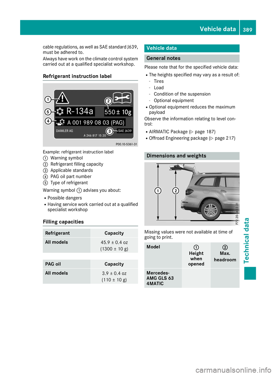
Refrigerant instruction label Example: refrigerant instruction label
0043 Warning symbol
0044 Refrigerant filling capacity
0087 Applicable standards
0085 PAG oil part number
0083 Type of refrigerant
Warning symbol 0043advises you about:
R Possible dangers
R Having service work carried out at a qualified
specialist workshop
Filling capacities Refrigerant Capacity
All models
45.9 ± 0.4 oz
(1300 ± 10 g) PAG oil Capacity
All models
3.9 ± 0.4 oz
(110 ± 10 g) Vehicle data
General notes
Please note that for the specified vehicle data: R The heights specified may vary as a result of:
- Tires
- Load
- Condition of the suspension
- Optional equipment
R Optional equipment reduces the maximum
payload
Observe the information relating to level con-
trol:
R AIRMATIC Package (Y page 187)
R Offroad Engineering package (Y page 217) Dimensions and weights
Missing values were not available at time of
going to print.
Model
0043 0043
Height when
opened 0044
0044
Max.
headroom Mercedes-
AMG GLS 63
4MATIC Vehicle data
389Technical data Z
Page 393 of 398
maximum permissible load have no influence on
the maximum water depth.
Missing values were not available at time of
going to print. Model Maximum
water
depth Vehicles with the AIRMATIC
package 19.7 in
(50 cm) Vehicles with the Off-Road
Engineering package
Off-road levels 1 and 2
19.7 in
(50 cm) Vehicles with the Off-Road
Engineering package
Off-road level 3
23.6 in
(60 cm) Mercedes-AMG vehicles
For more information about off-road fording, see
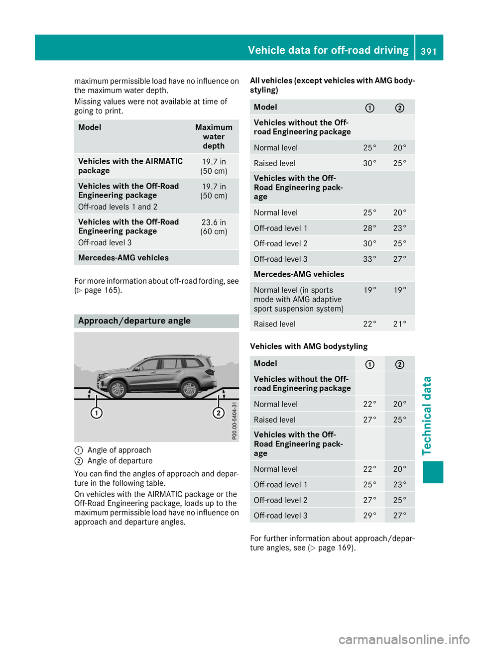
(Y page 165). Approach/departure angle
0043
Angle of approach
0044 Angle of departure
You can find the angles of approach and depar-
ture in the following table.
On vehicles with the AIRMATIC package or the
Off-Road Engineering package, loads up to the
maximum permissible load have no influence on approach and departure angles. All vehicles (except vehicles with AMG body-
styling) Model
0043 0043 0044
0044
Vehicles without the Off-
road Engineering package
Normal level 25° 20°
Raised level 30° 25°
Vehicles with the Off-
Road Engineering pack-
age
Normal level 25° 20°
Off-road level 1 28° 23°
Off-road level 2 30° 25°
Off-road level 3 33° 27°
Mercedes-AMG vehicles
Normal level (in sports
mode with AMG adaptive
sport suspension system) 19° 19°
Raised level 22° 21°
Vehicles with AMG bodystyling
Model
0043 0043 0044
0044
Vehicles without the Off-
road Engineering package
Normal level 22° 20°
Raised level 27° 25°
Vehicles with the Off-
Road Engineering pack-
age
Normal level 22° 20°
Off-road level 1 25° 23°
Off-road level 2 27° 25°
Off-road level 3 29° 27°
For further information about approach/depar-
ture angles, see (Y
page 169). Vehicle data for off-road driving
391Technical data Z