2019 MERCEDES-BENZ GLE SUV rear view mirror
[x] Cancel search: rear view mirrorPage 202 of 398
The cameras cover the immediate surroundings
of the vehicle. The 360° camera assists you, for
instance when parking or at exits with reduced
visibility.
You can show pictures from the 360° camera in full-screen mode or in seven different split-
screen views on the multimedia system display.
A split-screen view also includes a top view of
the vehicle. This view is calculated from the data supplied by the installed cameras (virtual cam-
era).
The six split-screen views are:
R Top view and picture from the rear view cam-
era (130° viewing angle)
R Top view and image from the front camera
(130° viewing angle without displaying the
maximum steering wheel angle)
R Top view and enlarged rear view
R Top view and enlarged front view
R Top view and trailer view (vehicles with trailer
tow hitch)
R Top view and rear-view images from the exte-
rior mirror cameras (rear wheel view)
R Top view and forward-view images from the
exterior mirror cameras (front wheel view)
When the function is active and you shift the
transmission from 005Bor005E to005C, the dynamic
guide lines are hidden.
When you shift between transmission positions 005B and 005E, you see the previously selected front
or rear view.
Distances measured by Parking Assist
PARKTRONIC will also be optically displayed:
R in split screen view as red or yellow brackets
around the vehicle icon in the top view, or
R at the bottom right as red or yellow brackets
around the vehicle symbol in full-screen mode
The line thickness and color of the brackets
show how far the vehicle is away from an object:
R yellow brackets with thin lines: Parking Assist
PARKTRONIC is active
R yellow brackets with normal lines: an object is
present in close range of the vehicle
R red line: an object is present in the immediate
close range of the vehicle
i The camera in the rear area is protected
from raindrops and dust by means of a flap.
When the camera is activated, this flap opens. The flap closes again in the following situa-
tions:
R you have finished the maneuvering process
R you switch the engine off
R you open the cargo compartment
Observe the notes on cleaning (Y page 331).
For technical reasons, the flap may remain
open briefly after the camera has been deac-
tivated.
Important safety notes The 360°camera is only an aid and may show a
distorted view of obstacles, show them incor-
rectly or not at all. The 360°camera is not a
substitute for attentive driving.
You are always responsible for safe maneuver-
ing and parking. Make sure that there are no
persons, animals or objects in the maneuvering
area while maneuvering and parking in parking
spaces.
You are always responsible for safety and must
continue to pay attention to your immediate
surroundings when parking and maneuvering.
This applies to the areas behind, in front of and beside the vehicle. You could otherwise endan-
ger yourself and others.
The 360° camera will not function or will func-
tion in a limited manner in the following situa-
tions:
R the doors are open
R the exterior mirrors are folded in
R the tailgate is open
R in heavy rain, snow or fog
R at night or in very dark places
R the cameras are exposed to very bright light
R the area is lit by fluorescent bulbs or LED
lighting (the display may flicker)
R there is a sudden change in temperature,
such as when driving into a heated garage in
winter
R the camera lenses are dirty or covered
R the vehicle components in which the cameras
are installed are damaged In this event, have
the camera position and setting checked at a qualified specialist workshop
Do not use the 360° camera under such cir-
cumstances. You can otherwise injure others or cause damage to objects or the vehicle. 200
Driving systemsDriving and parking
Page 203 of 398
Guide lines are always shown at road level. In
trailer mode, the guide lines are shown at the
level of the trailer coupling.
The field of vision and other functions of the
camera system may be restricted due to addi-
tional accessories on the rear of the vehicle (e.g.
license plate holder, bicycle rack).
On vehicles with height-adjustable chassis,
depending on technical conditions, leaving the
standard height can result in:
R inaccuracies in the guide lines
R inaccuracies in the display of generated
images (top view)
Activation conditions The 360° camera image can be displayed in the
following situations:
R your vehicle is equipped with a 360° camera
R the SmartKey is in key position 0048in the igni-
tion lock
R the multimedia system is switched on
Switching on the 360° camera X
Press the 00D4button in the center console
for longer than two seconds.
Depending on whether transmission position
005B or005E is selected, the following appears:
R a split screen with top view and the image
from the front camera or
R a split screen with top view and the image
from the rear view camera
or
X Press the 00D4button in the center console.
The vehicle menu is displayed.
X Select 360°
360° Camera Camera and press 7to confirm.
Depending on whether transmission position
005B or005E is selected, the following appears:
R a split screen with top view and the image
from the front camera or
R a split screen with top view and the image
from the rear view camera
Activating the 360° camera using
reverse gear The 360° camera images can be automatically
displayed by engaging reverse gear. X
Make sure that the SmartKey is in position 0048
in the ignition lock.
X Make sure that the Activation by R gear Activation by R gear
function is selected on the multimedia system (see the Digital Operator's Manual).
X To show the 360° camera image: engage
reverse gear.
The multimedia system shows the area
behind the vehicle in split-screen mode. You
see the top view of the vehicle and the image from the rear view camera.
Selecting the split-screens or 180° view Selecting split-screen view
X To switch to the line with the vehicle icons:
slide 5the controller.
X To select one of the vehicle icons: turn 3
the controller.
X To switch to 180° View 180° View:turn 3 the con-
troller to select 180° View
180° Viewand press7to
confirm.
i The
180°
180° View
Viewoption is only available in the
following views:
R Top view with picture from the rear view
camera
R Top view with picture from the front camera
Displays in the multimedia system Important safety notes
The camera system may show a distorted view
of obstacles, show them incorrectly or not at all. Obstacles are not shown by the system in the
following locations:
R under the front and rear bumpers
R very close to the front and rear bumpers
R in the area immediately above the tailgate
handle
R very close to the exterior mirrors
R in the transitional areas between the various
cameras in the virtual top view
! Objects not at ground level may appear to
be further away than they actually are, e.g.:
R the bumper of a parked vehicle
R the drawbar of a trailer
R the ball coupling of a trailer tow hitch Driving systems
201Driving and parking Z
Page 204 of 398
R
the rear section of an HGV
R a slanted post
Use the guidelines only for orientation.
Approach objects no further than the bottom- most guideline.
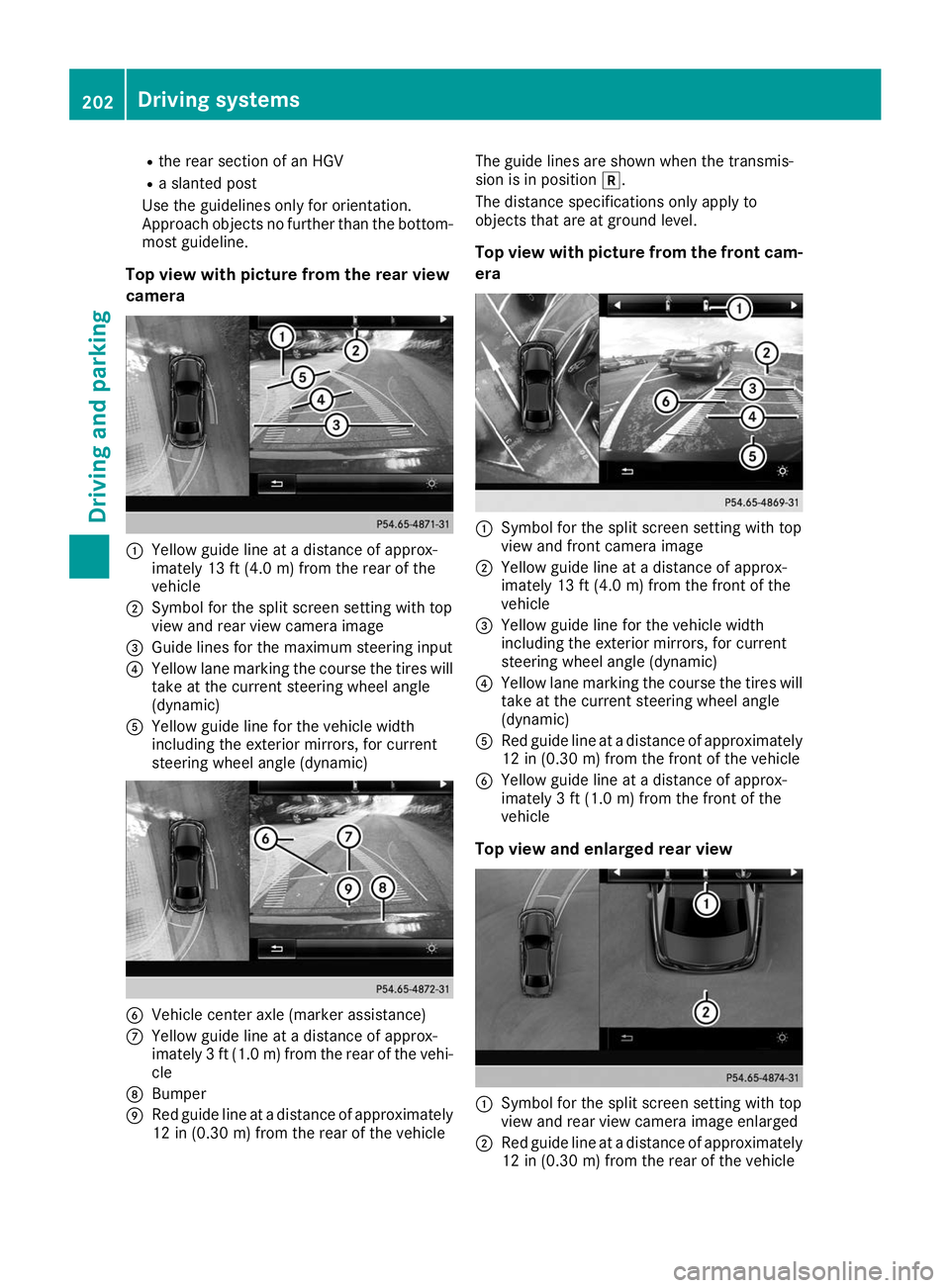
Top view with picture from the rear view
camera 0043
Yellow guide line at a distance of approx-
imately 13 ft (4.0 m) fromthe rear of the
vehicle
0044 Symbol for the split screen setting with top
view and rear view camera image
0087 Guide lines for the maximum steering input
0085 Yellow lane marking the course the tires will
take at the current steering wheel angle
(dynamic)
0083 Yellow guide line for the vehicle width
including the exterior mirrors, for current
steering wheel angle (dynamic) 0084
Vehicle center axle (marker assistance)
006B Yellow guide line at a distance of approx-
imately 3 ft (1.0 m) fromthe rear of the vehi-
cle
006C Bumper
006D Red guide line at a distance of approximately
12 in (0.30 m) fromthe rear of the vehicle The guide lines are shown when the transmis-
sion is in position
005E.
The distance specifications only apply to
objects that are at ground level.
Top view with picture from the front cam-
era 0043
Symbol for the split screen setting with top
view and front camera image
0044 Yellow guide line at a distance of approx-
imately 13 ft (4.0 m) fromthe front of the
vehicle
0087 Yellow guide line for the vehicle width
including the exterior mirrors, for current
steering wheel angle (dynamic)
0085 Yellow lane marking the course the tires will
take at the current steering wheel angle
(dynamic)
0083 Red guide line at a distance of approximately
12 in (0.30 m) fromthe front of the vehicle
0084 Yellow guide line at a distance of approx-
imately 3 ft (1.0 m) fromthe front of the
vehicle
Top view and enlarged rear view 0043
Symbol for the split screen setting with top
view and rear view camera image enlarged
0044 Red guide line at a distance of approximately
12 in (0.30 m)from the rear of the vehicle 202
Driving systemsDriving and parking
Page 205 of 398
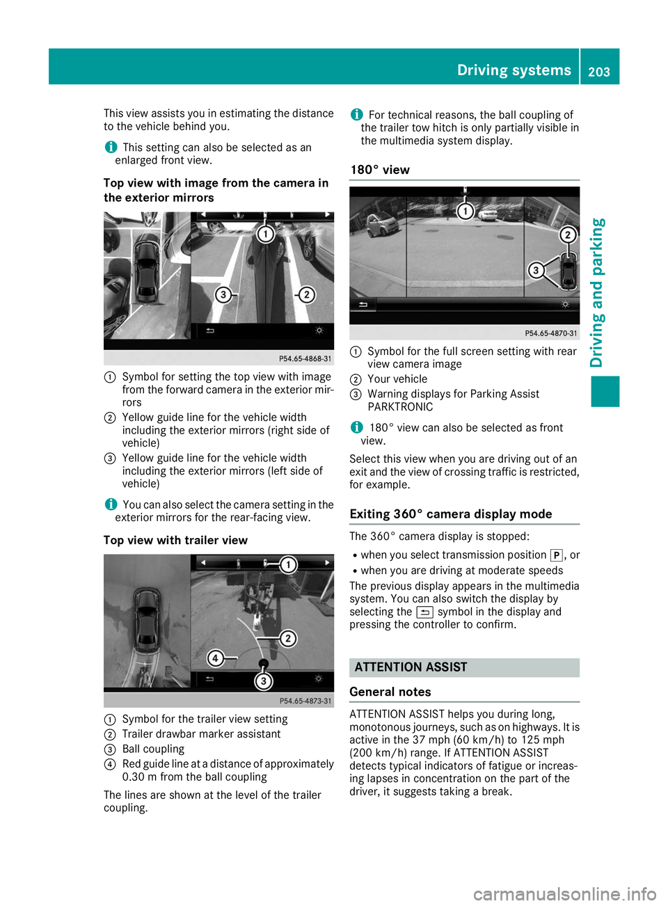
This view assists you in estimating the distance
to the vehicle behind you.
i This setting can also be selected as an
enlarged front view.
Top view with image from the camera in
the exterior mirrors 0043
Symbol for setting the top view with image
from the forward camera in the exterior mir-
rors
0044 Yellow guide line for the vehicle width
including the exterior mirrors (right side of
vehicle)
0087 Yellow guide line for the vehicle width
including the exterior mirrors (left side of
vehicle)
i You can also select the camera setting in the
exterior mirrors for the rear-facing view.
Top view with trailer view 0043
Symbol for the trailer view setting
0044 Trailer drawbar marker assistant
0087 Ball coupling
0085 Red guide line at a distance of approximately
0.30 m from the ball coupling
The lines are shown at the level of the trailer
coupling. i
For technical reasons, the ball coupling of
the trailer tow hitch is only partially visible in
the multimedia system display.
180° view 0043
Symbol for the full screen setting with rear
view camera image
0044 Your vehicle
0087 Warning displays for Parking Assist
PARKTRONIC
i 180° view can also be selected as front
view.
Select this view when you are driving out of an
exit and the view of crossing traffic is restricted,
for example.
Exiting 360° camera display mode The 360° camera display is stopped:
R
when you select transmission position 005D, or
R when you are driving at moderate speeds
The previous display appears in the multimedia
system. You can also switch the display by
selecting the 0039symbol in the display and
pressing the controller to confirm. ATTENTION ASSIST
General notes ATTENTION ASSIST helps you during long,
monotonous journeys, such as on highways. It is
active in the 37 mph (60 km/h) to 125 mph
(200 km/h) range. If ATTENTION ASSIST
detects typical indicators of fatigue or increas-
ing lapses in concentration on the part of the
driver, it suggests taking a break. Driving systems
203Driving and parking Z
Page 226 of 398

Most U.S. states and all Canadian provinces
require by law:
R Safety chains between the towing vehicle and
the trailer. The chains should be cross-woundunder the trailer drawbar. They must be fas-
tened to the vehicle's trailer coupling, not to
the bumper or the axle.
Leave enough play in the chains to make tight
cornering possible.
R A separate brake system for certain types of
trailer.
R Safety switch for braked trailers. Check the
specific legal requirements applicable to your
state.
If the trailer becomes detached from the tow-
ing vehicle, the safety feature triggers the
trailer brakes. Towing a trailer
There are numerous legal requirements con-
cerning the towing of a trailer, e.g. speed restric-
tions. Make sure that your car/trailer combina- tion complies with the local regulations:
R in your place of residence
R in the location to which you are driving
The police and local authorities can provide reli-
able information.
Observe the following when towing a trailer:
R To gain driving experience and to become
accustomed to the new handling characteris-
tics, you should practice the following in a
traffic-free location:
- cornering
- stopping
- backing up
R Before driving, check:
- trailer tow hitch
- safety switch for braked trailers
- safety chains
- electrical connections
- lights
- wheels
R Adjust the exterior mirrors to provide an
unobstructed view of the rear section of the
trailer.
R If the trailer has electronically controlled
brakes, pull away carefully. Brake manually using the brake controller and check whether
the brakes function correctly.
R Secure any objects on the trailer to prevent
the cargo from slipping when the vehicle is in
motion.
R When you couple up a trailer, check at regular
intervals that the load is firmly secured. If the trailer is equipped with trailer lights and
brakes, check the trailer to ensure that these
are working.
R Bear in mind that the handling will be less
stable when towing a trailer than when driving
without one. Avoid sudden steering move-
ments.
R The vehicle/trailer combination is heavier,
accelerates more slowly, has a decreased
gradient climbing capability and a longer
braking distance.
It is more susceptible to side winds and
requires more careful steering.
R If possible, do not brake suddenly, but instead
depress the brake pedal moderately at first sothat the trailer can activate its brakes. Then
increase the pressure on the brake pedal.
R If the automatic transmission repeatedly
shifts between gears on uphill or downhill gra-
dients, shift to a lower gear using the left-hand
steering wheel paddle shifter.
A lower gear and lower speed reduce the risk of engine failure.
R When driving downhill, shift to a lower gear to
utilize the engine's braking effect.
Avoid continuous brake application as this
may overheat the vehicle brakes and, if instal- led, the trailer brakes.
R If the coolant temperature increases dramat-
ically while the air-conditioning system is
switched on, switch off the air-conditioning
system.
Coolant heat can also be dissipated by open-
ing the windows and switching the ventilation blower and the interior temperature to the
highest level.
R When overtaking, pay particular attention to
the extended length of your vehicle/trailer
combination.
Due to the length of the vehicle/trailer com-
bination, you require additional road space in
relation to the vehicle you are overtaking
before you can change back to the original
lane. 224
Towing a trailerDriving and parking
Page 307 of 398
The stowage compartments in the doors provide
space for bottles with a capacity of up to
34 fl. oz. (1.0 l).
The bottles are not secured or prevented from
tipping over. Therefore, do not place any open
drink containers in the stowage compartments.
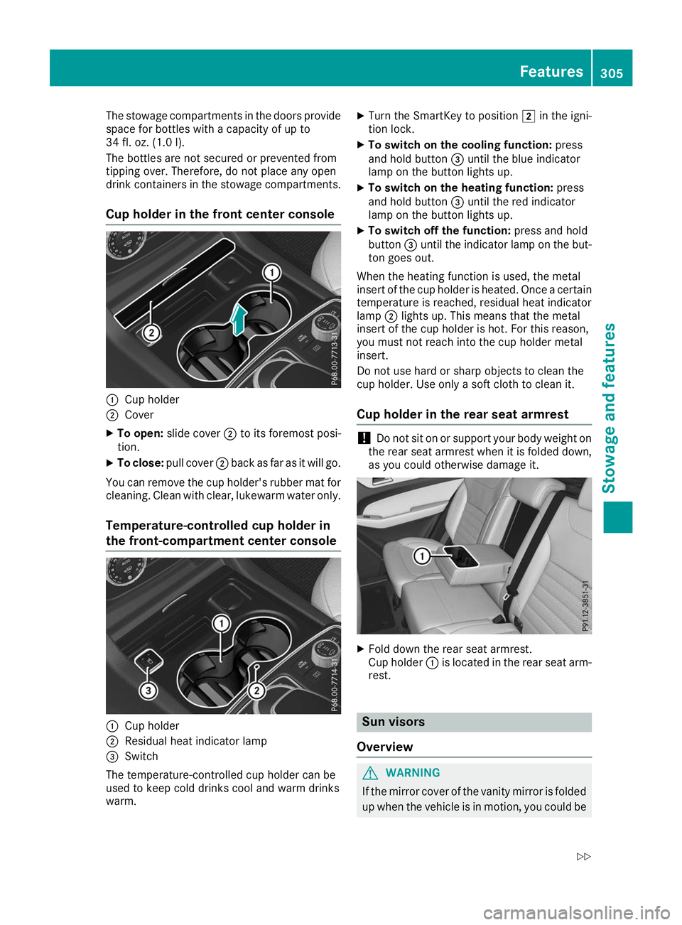
Cup holder in the front center console 0043
Cup holder
0044 Cover
X To open: slide cover 0044to its foremost posi-
tion.
X To close: pull cover 0044back as far as it will go.
You can remove the cup holder's rubber mat for
cleaning. Clean with clear, lukewarm water only.
Temperature-controlled cup holder in
the front-compartment center console 0043
Cup holder
0044 Residual heat indicator lamp
0087 Switch
The temperature-controlled cup holder can be
used to keep cold drinks cool and warm drinks
warm. X
Turn the SmartKey to position 0048in the igni-
tion lock.
X To switch on the cooling function: press
and hold button 0087until the blue indicator
lamp on the button lights up.
X To switch on the heating function: press
and hold button 0087until the red indicator
lamp on the button lights up.
X To switch off the function: press and hold
button 0087until the indicator lamp on the but-
ton goes out.
When the heating function is used, the metal
insert of the cup holder is heated. Once a certain temperature is reached, residual heat indicator
lamp 0044lights up. This means that the metal
insert of the cup holder is hot. For this reason,
you must not reach into the cup holder metal
insert.
Do not use hard or sharp objects to clean the
cup holder. Use only a soft cloth to clean it.
Cup holder in the rear seat armrest !
Do not sit on or support your body weight on
the rear seat armrest when it is folded down,
as you could otherwise damage it. X
Fold down the rear seat armrest.
Cup holder 0043is located in the rear seat arm-
rest. Sun visors
Overview G
WARNING
If the mirror cover of the vanity mirror is folded up when the vehicle is in motion, you could be Features
305Stowage and features
Z
Page 318 of 398

Information on Roadside Assistance
(Y
page 29).
Downloading routes Downloading routes allows you to transfer and
save predefined routes in the navigation sys-
tem.
A route can be prepared and sent either by a
customer service representative or under "Own- ers Online" at http://www.mbusa.com.
Each route can include up to four way points.
Once a route has been received by the naviga-
tion system, you will see the Do
Do you you want
want to
to
start route guidance? Destination
start route guidance? Destination
Received destination has been saved Received destination has been saved
in "Previous destinations". in "Previous destinations". message on
the multimedia system display.
The route is saved.
X To start route guidance: selectYes
Yes.
An overview of the route is shown in the dis-
play.
If you select No No, the saved route can be called
up later in the navigation menu.
X Select Start
Start.
Route guidance starts.
Downloaded and saved routes can be called up again.
Speed alert You can define the upper speed limit, which
must not be exceeded by the vehicle.
If the vehicle exceeds the set speed, a message
is sent to the Customer Assistance Center. The
Customer Assistance Center then forwards this
information to you.
You can select the way in which you receive this information beforehand. Possible options
include text message, e-mail or an automated
call.
The data you receive contains the following
information:
R the location where the speed limit was excee-
ded
R the time at which the speed limit was excee-
ded
R the selected speed limit which was exceeded Geo fencing Geo fencing allows you to select areas which the
vehicle should not enter or leave. You will be
informed if the vehicle crosses the boundaries
of the selected areas. You can select the way in
which you receive this information beforehand.
Possible options include text message, e-mail or an automated call.
The area can be determined as either a circle or
a polygon with a maximum of ten corners. You
can specify up to ten areas simultaneously. Dif- ferent settings are possible for each area.
These settings can be called up under "Owners
Online" at http://www.mbusa.com.
Alternatively, you can also trigger an Info call
and notify the customer service representative
that you wish to activate geo-fencing.
Currently inactive areas can be activated by text message.
Triggering the vehicle alarm With this function, you can trigger the vehicle's
panic alarm via text message. An alarm sounds
and the exterior lighting flashes. Depending on
the setting, the panic alarm lasts five or ten sec-
onds. Afterwards, the alarm switches off. Garage door opener
General notes The HomeLink
®
garage door opener integrated
in the rear-view mirror allows you to operate up
to three different door and gate systems.
Use the integrated garage door opener only on
garage doors that:
R have safety stop and reverse features and
R meet current U.S. federal safety standards
Once programmed, the integrated garage door
opener in the rear-view mirror will assume the
function of the garage door system's remote
control. Please also read the operating instruc-
tions for the garage door system.
When programming a garage door opener, park
the vehicle outside the garage. Do not run the
engine while programming.
Certain garage door drives are incompatible
with the integrated garage door opener. If you
have difficulty programming the integrated 316
FeaturesStowage and features
Page 319 of 398

garage door opener, contact a Mercedes-Benz
Service Center.
Alternatively, you can call the following tele-
phone assistance services:
R USA: Mercedes-Benz Customer Assistance
Center at 1-800-FOR-MERCedes
R Canada: Customer Service at
1-800-387-0100
R HomeLink ®
hotline 1-800-355-3515 (free of
charge)
More information on HomeLink ®
and/or com-
patible products is also available on the Internet
at http://www.homelink.com .
Notes on the declaration of conformity
(Y page 30).
USA: FCC ID: CB2HMIHL4
Canada: IC: 279B-HMIHL4
Important safety notes G
WARNING
When you operate or program the door with
the integrated garage door opener, persons in the range of movement of the door may
become trapped or be struck by the door.
There is a risk of injury.
When using the integrated garage door
opener, always make sure that nobody is
within the range of movement of the door. G
WARNING
Combustion engines emit poisonous exhaust
gases such as carbon monoxide. Inhaling
these exhaust gases leads to poisoning. There is a risk of fatal injury. Therefore never leave
the engine running in enclosed spaces with-
out sufficient ventilation.
Programming Programming the buttons
Pay attention to the "Important safety notes"
(Y page 317). Garage door remote control
0083is not included
with the integrated garage door opener.
X Turn the SmartKey to position 0048in the igni-
tion lock (Y page 135).
X Select one of buttons 0044to0085 to use to con-
trol the garage door drive.
X To start programming mode: press and
hold one of buttons 0044to0085 on the integrated
garage door opener.
The garage door opener is now in program-
ming mode. After a short time, indicator
lamp 0043lights up yellow.
Indicator lamp 0043lights up yellow as soon as
button 0044,0087or0085 is stored for the first time.
If the selected button has already been pro-
gramed, indicator lamp 0043will only light up
yellow after ten seconds have elapsed.
X Release button 0044,0087or0085. Indicator
lamp 0043flashes yellow.
X To program the remote control: point
garage door remote control 0083towards but-
tons 0044to0085 on the rear-view mirror at a dis-
tance of 2 to 8 in (5 to 20 cm).
X Press and hold button 0084on remote control
0083 until indicator lamp 0043lights up green.
When indicator lamp 0043lights up green: pro-
gramming is finished.
When indicator lamp 0043flashes green: pro-
gramming was successful. The next step is to synchronize the rolling code (Y page 318).
X Release button 0084on remote control 0083for
the garage door drive system.
If indicator lamp 0043lights up red: repeat the
programing procedure for the corresponding
button on the rear-view mirror. When doing
so, vary the distance between remote control 0083 and the rear-view mirror.
The required distance between remote con-
trol 0083and the integrated garage door opener
depends on the garage door drive system. Features
317Stowage and features Z