2019 MERCEDES-BENZ GLE seats
[x] Cancel search: seatsPage 321 of 398
operate in the frequency range of 280 to
433 MHz.
R Replace the batteries in garage door remote
control 0083. This increases the likelihood that
garage door remote control 0083will transmit a
strong and precise signal to the integrated
garage door opener.
R When programming, hold remote control 0083
at varying distances and angles from but-
tons 0044to0085 which you are programming. Try
various angles at a distance between 2and
8 inches (5to 20 cm) or at the same angle but at varying distances.
R If a further remote control 0083is available for
the same garage door drive, repeat the same programming steps with this remote control
0083. Before performing these steps, make sure
that new batteries have been installed in
garage door drive remote control 0083.
R Note that some remote controls only transmit
for a limited amount of time (the indicator
lamp on the remote control goes out). Press
button 0084on remote control 0083again before
transmission ends.
R Align the antenna cable of the garage door
opener unit. This can improve signal recep-
tion/transmission.
Opening/closing the garage door After it has been programmed, the integrated
garage door opener performs the function of the
garage door system remote control. Please also read the operating instructions for the garage
door system.
X Turn the SmartKey to position 0048in the igni-
tion lock (Y page 135).
X Press button 0044,0087or0085 which you pro-
grammed to operate the garage door.
Garage door system with a fixed code: indi-
cator lamp 0043lights up green.
Garage door system with a rolling code: indi-
cator lamp 0043flashes green.
The transmitter will transmit a signal as long
as the button is pressed. The transmission is
halted after a maximum of ten seconds and
indicator lamp 0043lights up yellow.
X Press button 0044,0087or0085 again if necessary. Clearing the memory Make sure that you clear the memory of the
integrated garage door opener before selling the
vehicle.
X Turn the SmartKey to position 0048in the igni-
tion lock (Y page 135).
X Press and hold buttons 0044and 0085.
Indicator lamp 0043initially lights up yellow and
then green.
X Release buttons 0044and 0085.
The memory of the integrated garage door
opener in the rear-view mirror is cleared. Floormats
G
WARNING
Objects in the driver's footwell can restrict the pedal travel or obstruct a depressed pedal.
The operating and road safety of the vehicle is
jeopardized. There is a risk of an accident.
Make sure that all objects in the vehicle are
stowed correctly, and that they cannot enter
the driver's footwell. Install the floormats
securely and as specified in order to ensure
sufficient clearance for the pedals. Do not use loose floormats and do not place floormats on
top of one another. X
Driver's seat/front-passenger seat: slide
the respective seat back.
X Rear seats: slide the corresponding front
seat forwards.
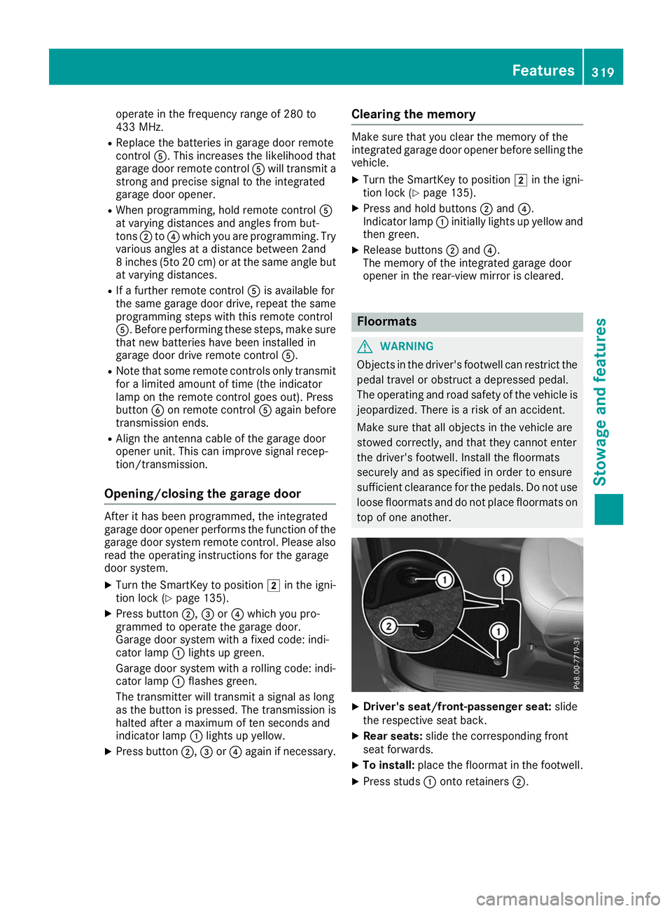
X To install: place the floormat in the footwell.
X Press studs 0043onto retainers 0044. Features
319Stowage and features Z
Page 342 of 398
X
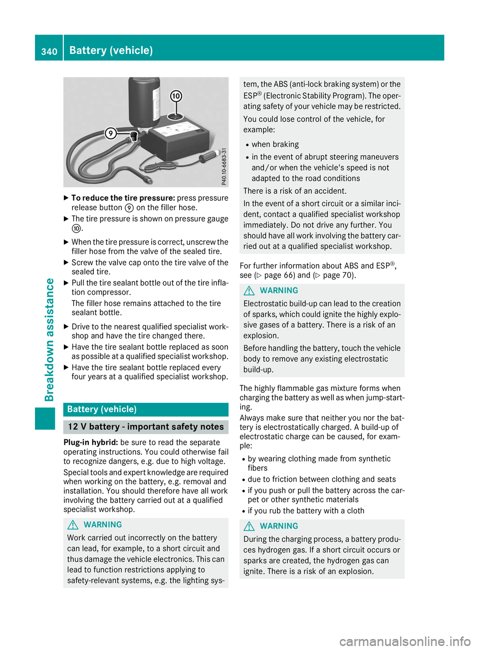
To reduce the tire pressure: press pressure
release button 006Don the filler hose.
X The tire pressure is shown on pressure gauge
006E.
X When the tire pressure is correct, unscrew the
filler hose from the valve of the sealed tire.
X Screw the valve cap onto the tire valve of the
sealed tire.
X Pull the tire sealant bottle out of the tire infla-
tion compressor.
The filler hose remains attached to the tire
sealant bottle.
X Drive to the nearest qualified specialist work-
shop and have the tire changed there.
X Have the tire sealant bottle replaced as soon
as possible at a qualified specialist workshop.
X Have the tire sealant bottle replaced every
four years at a qualified specialist workshop. Battery (vehicle)
12 V battery - important safety notes
Plug-in hybrid: be sure to read the separate
operating instructions. You could otherwise fail
to recognize dangers, e.g. due to high voltage.
Special tools and expert knowledge are required
when working on the battery, e.g. removal and
installation. You should therefore have all work
involving the battery carried out at a qualified
specialist workshop. G
WARNING
Work carried out incorrectly on the battery
can lead, for example, to a short circuit and
thus damage the vehicle electronics. This can lead to function restrictions applying to
safety-relevant systems, e.g. the lighting sys- tem, the ABS (anti-lock braking system) or the
ESP ®
(Electronic Stability Program). The oper-
ating safety of your vehicle may be restricted.
You could lose control of the vehicle, for
example:
R when braking
R in the event of abrupt steering maneuvers
and/or when the vehicle's speed is not
adapted to the road conditions
There is a risk of an accident.
In the event of a short circuit or a similar inci-
dent, contact a qualified specialist workshop
immediately. Do not drive any further. You
should have all work involving the battery car- ried out at a qualified specialist workshop.
For further information about ABS and ESP ®
,
see (Y page 66) and (Y page 70). G
WARNING
Electrostatic build-up can lead to the creation of sparks, which could ignite the highly explo-
sive gases of a battery. There is a risk of an
explosion.
Before handling the battery, touch the vehicle body to remove any existing electrostatic
build-up.
The highly flammable gas mixture forms when
charging the battery as well as when jump-start- ing.
Always make sure that neither you nor the bat-
tery is electrostatically charged. A build-up of
electrostatic charge can be caused, for exam-
ple:
R by wearing clothing made from synthetic
fibers
R due to friction between clothing and seats
R if you push or pull the battery across the car-
pet or other synthetic materials
R if you rub the battery with a cloth G
WARNING
During the charging process, a battery produ- ces hydrogen gas. If a short circuit occurs or
sparks are created, the hydrogen gas can
ignite. There is a risk of an explosion. 340
Battery (vehicle)Breakdo
wn assis tance
Page 357 of 398
R
incorrectly set tire pressure
R sudden loss of tire pressure, e.g. from a for-
eign object that has penetrated the tire
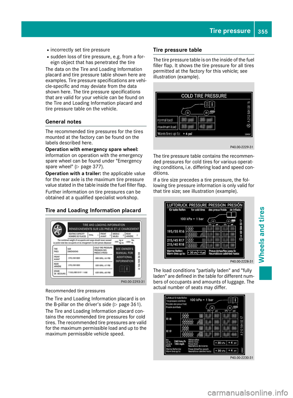
The data on the Tire and Loading Information
placard and tire pressure table shown here are
examples. Tire pressure specifications are vehi- cle-specific and may deviate from the data
shown here. The tire pressure specifications
that are valid for your vehicle can be found on
the Tire and Loading Information placard and
tire pressure table on the vehicle.
General notes The recommended tire pressures for the tires
mounted at the factory can be found on the
labels described here.
Operation with emergency spare wheel:
information on operation with the emergency
spare wheel can be found under "Emergency
spare wheel" (Y page 377).
Operation with a trailer: the applicable value
for the rear axle is the maximum tire pressure
value stated in the table inside the fuel filler flap.
Further information on tire pressures can be
obtained at a qualified specialist workshop.
Tire and Loading Information placard Recommended tire pressures
The Tire and Loading Information placard is on
the B-pillar on the driver's side (Y page 361).
The Tire and Loading Information placard con-
tains the recommended tire pressures for cold
tires. The recommended tire pressures are valid for the maximum permissible load and up to the
maximum permissible vehicle speed. Tire pressure table The tire pressure table is on the inside of the fuel
filler flap. It shows the tire pressure for all tires
permitted at the factory for this vehicle; see
illustration (example). The tire pressure table contains the recommen-
ded pressures for cold tires for various operat-
ing conditions, i.e. differing load and speed con-
ditions.
If a tire size precedes a tire pressure, the fol-
lowing tire pressure information is only valid for that tire size; see illustration (example). The load conditions "partially laden" and "fully
laden" are defined in the table for different num- bers of occupants and amounts of luggage. The
actual number of seats may differ. Tire pressure
355Wheels and tires Z
Page 364 of 398
0043
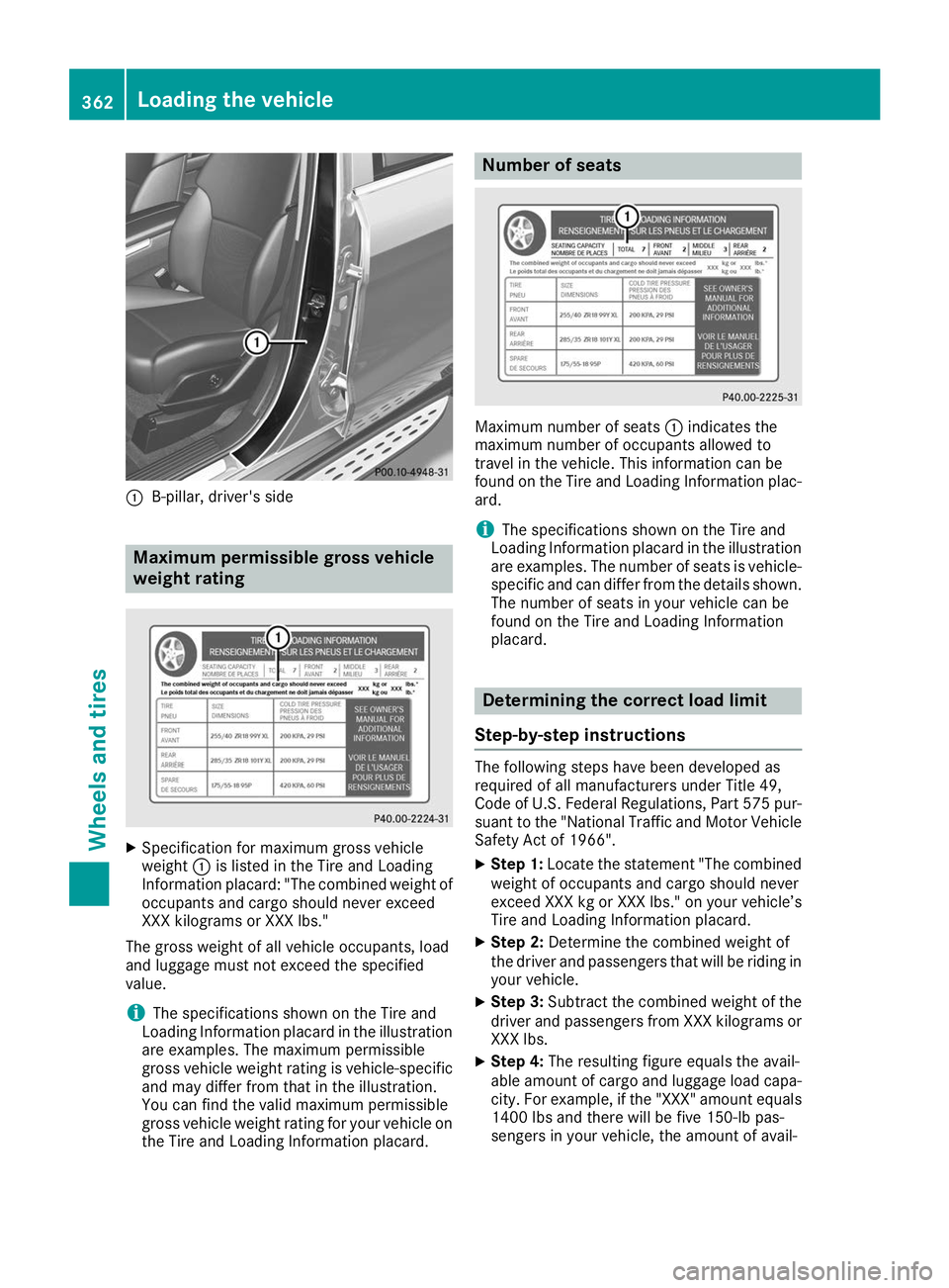
B-pillar, driver's side Maximum permissible gross vehicle
weight rating X
Specification for maximum gross vehicle
weight 0043is listed in the Tire and Loading
Information placard: "The combined weight of occupants and cargo should never exceed
XXX kilograms or XXX lbs."
The gross weight of all vehicle occupants, load
and luggage must not exceed the specified
value.
i The specifications shown on the Tire and
Loading Information placard in the illustration are examples. The maximum permissible
gross vehicle weight rating is vehicle-specific
and may differ from that in the illustration.
You can find the valid maximum permissible
gross vehicle weight rating for your vehicle on
the Tire and Loading Information placard. Number of seats
Maximum number of seats
0043indicates the
maximum number of occupants allowed to
travel in the vehicle. This information can be
found on the Tire and Loading Information plac-
ard.
i The specifications shown on the Tire and
Loading Information placard in the illustration
are examples. The number of seats is vehicle- specific and can differ from the details shown.
The number of seats in your vehicle can be
found on the Tire and Loading Information
placard. Determining the correct load limit
Step-by-step instructions The following steps have been developed as
required of all manufacturers under Title 49,
Code of U.S. Federal Regulations, Part 575 pur-
suant to the "National Traffic and Motor Vehicle
Safety Act of 1966".
X Step 1: Locate the statement "The combined
weight of occupants and cargo should never
exceed XXX kg or XXX lbs." on your vehicle’s
Tire and Loading Information placard.
X Step 2: Determine the combined weight of
the driver and passengers that will be riding in your vehicle.
X Step 3: Subtract the combined weight of the
driver and passengers from XXX kilograms or
XXX lbs.
X Step 4: The resulting figure equals the avail-
able amount of cargo and luggage load capa-
city. For example, if the "XXX" amount equals 1400 lb s andthere will be five 150-lb pas-
sengers in your vehicle, the amount of avail- 362
Loading the vehicleWheels and tires
Page 373 of 398
Sidewall
The part of the tire between the tread and the
bead.
Weight of optional extras The combined weight of those optional extras
that weigh more than the replaced standard
parts and more than 2.3 kg (5 lbs). These
optional extras, such as high-performance
brakes, level control, a roof rack or a high-per-
formance battery, are not included in the curb
weight and the weight of the accessories.
TIN (Tire Identification Number) This is a unique identifier which can be used by
a tire manufacturer to identify tires, for example for a product recall, and thus identify the pur-
chasers. The TIN is made up of the manufactur-
er's identity code, tire size, tire type code and
the manufacturing date.
Load bearing index
The load bearing index (also load index) is a code that contains the maximum load bearing capa-
city of a tire.
Traction
Traction is the result of friction between the tires and the road surface.
TWR (Tongue Weight Rating)
The TWR specifies the maximum permissible
weight that the ball coupling of the trailer tow
hitch can support.
Treadwear indicators Narrow bars (tread wear bars) that are distrib-
uted over the tire tread. If the tire tread is level
with the bars, the wear limit of 00CDin (1.6 mm)
has been reached.
Occupant distribution
The distribution of occupants in a vehicle at their designated seating positions.
Total load limit Nominal load and luggage load plus 68 kg
(150 lbs) multiplied by the number of seats in
the vehicle. Changing a wheel
Flat tire
The "Breakdown assistance" section
(Y page 335) contains information and notes on
how to deal with a flat tire. Information on driv-
ing with MOExtended tires in the event of a flat
tire can be found under "MOExtended tires (tires with run-flat characteristics" (Y page 336).
Vehicles with an emergency spare wheel: in
the event of a flat tire, mount the emergency
spare wheel according to the description under "Mounting a wheel" (Y page 372). Rotating the wheels
G
WARNING
Interchanging the front and rear wheels may
severely impair the driving characteristics if
the wheels or tires have different dimensions. The wheel brakes or suspension components
may also be damaged. There is a risk of acci-
dent.
Rotate front and rear wheels only if the wheels and tires are of the same dimensions.
! On vehicles equipped with a tire pressure
monitor, electronic components are located
in the wheel.
Tire-mounting tools should not be used near
the valve. This could damage the electronic
components.
Only have tires changed at a qualified spe-
cialist workshop.
Always observe the instructions and safety
notes in the "Mounting a wheel" section
(Y page 372).
The wear patterns on the front and rear tires
differ, depending on the operating conditions.
Rotate the wheels before a clear wear pattern
has formed on the tires. Front tires typically
wear more on the shoulders and the rear tires in
the center.
On vehicles that have the same size front and
rear wheels, you can rotate the wheels accord-
ing to the intervals in the tire manufacturer's
warranty book in your vehicle documents. If no
warranty book is available, the tires should be
rotated every 3,000 to 6,000 miles (5,000 to
10,000 km). Depending on tire wear, this may Changing a wheel
371Wheels and tires Z