2019 MERCEDES-BENZ GLE roof
[x] Cancel search: roofPage 373 of 398

Sidewall
The part of the tire between the tread and the
bead.
Weight of optional extras The combined weight of those optional extras
that weigh more than the replaced standard
parts and more than 2.3 kg (5 lbs). These
optional extras, such as high-performance
brakes, level control, a roof rack or a high-per-
formance battery, are not included in the curb
weight and the weight of the accessories.
TIN (Tire Identification Number) This is a unique identifier which can be used by
a tire manufacturer to identify tires, for example for a product recall, and thus identify the pur-
chasers. The TIN is made up of the manufactur-
er's identity code, tire size, tire type code and
the manufacturing date.
Load bearing index
The load bearing index (also load index) is a code that contains the maximum load bearing capa-
city of a tire.
Traction
Traction is the result of friction between the tires and the road surface.
TWR (Tongue Weight Rating)
The TWR specifies the maximum permissible
weight that the ball coupling of the trailer tow
hitch can support.
Treadwear indicators Narrow bars (tread wear bars) that are distrib-
uted over the tire tread. If the tire tread is level
with the bars, the wear limit of 00CDin (1.6 mm)
has been reached.
Occupant distribution
The distribution of occupants in a vehicle at their designated seating positions.
Total load limit Nominal load and luggage load plus 68 kg
(150 lbs) multiplied by the number of seats in
the vehicle. Changing a wheel
Flat tire
The "Breakdown assistance" section
(Y page 335) contains information and notes on
how to deal with a flat tire. Information on driv-
ing with MOExtended tires in the event of a flat
tire can be found under "MOExtended tires (tires with run-flat characteristics" (Y page 336).
Vehicles with an emergency spare wheel: in
the event of a flat tire, mount the emergency
spare wheel according to the description under "Mounting a wheel" (Y page 372). Rotating the wheels
G
WARNING
Interchanging the front and rear wheels may
severely impair the driving characteristics if
the wheels or tires have different dimensions. The wheel brakes or suspension components
may also be damaged. There is a risk of acci-
dent.
Rotate front and rear wheels only if the wheels and tires are of the same dimensions.
! On vehicles equipped with a tire pressure
monitor, electronic components are located
in the wheel.
Tire-mounting tools should not be used near
the valve. This could damage the electronic
components.
Only have tires changed at a qualified spe-
cialist workshop.
Always observe the instructions and safety
notes in the "Mounting a wheel" section
(Y page 372).
The wear patterns on the front and rear tires
differ, depending on the operating conditions.
Rotate the wheels before a clear wear pattern
has formed on the tires. Front tires typically
wear more on the shoulders and the rear tires in
the center.
On vehicles that have the same size front and
rear wheels, you can rotate the wheels accord-
ing to the intervals in the tire manufacturer's
warranty book in your vehicle documents. If no
warranty book is available, the tires should be
rotated every 3,000 to 6,000 miles (5,000 to
10,000 km). Depending on tire wear, this may Changing a wheel
371Wheels and tires Z
Page 383 of 398

Information regarding technical data
Plug-in hybrid: be sure to read the separate
Operator's Manual. Otherwise, you may not rec- ognize dangers.
i The data stated here specifically refers to a
vehicle with standard equipment. Consult an
authorized Mercedes-Benz Center for the
data for all vehicle variants and trim levels. Vehicle electronics
Installing two-way radios and mobile
phones (RF transmitters)
G
WARNING
The electromagnetic radiation from two-way
radios can interfere with the vehicle electron-
ics if two-way radios are manipulated or ret-
rofitted incorrectly. This could jeopardize the
operating safety of the vehicle. There is a risk of an accident.
You should have all work on electrical and
electronic components carried out at a quali-
fied specialist workshop. G
WARNING
If you incorrectly operate two-way radios in
the vehicle, the electromagnetic radiation
may interfere with the vehicle electronics, for example if:
R the two-way radio is not connected to an
exterior antenna
R the exterior antenna is not correctly moun-
ted or is not low-reflection
This could jeopardize the operating safety of
the vehicle. There is a risk of an accident.
Have the low-reflection exterior antenna
installed at a qualified specialist workshop.
Always connect two-way radios to the low-
reflection exterior antenna when operating in the vehicle.
! The operating permit may be invalidated if
the instructions for installation and use of
two-way radios are not observed. In particular, the following conditions must be
complied with:
R only approved wavebands may be used
R observe the maximum permissible output
in these wavebands
R only approved antenna positions may be
used
Excessive levels of electromagnetic radiation
may cause damage to your health and the health of others. Using an exterior antenna takes into
account current scientific discussions relating
to the possible health hazards that may result
from electromagnetic fields.
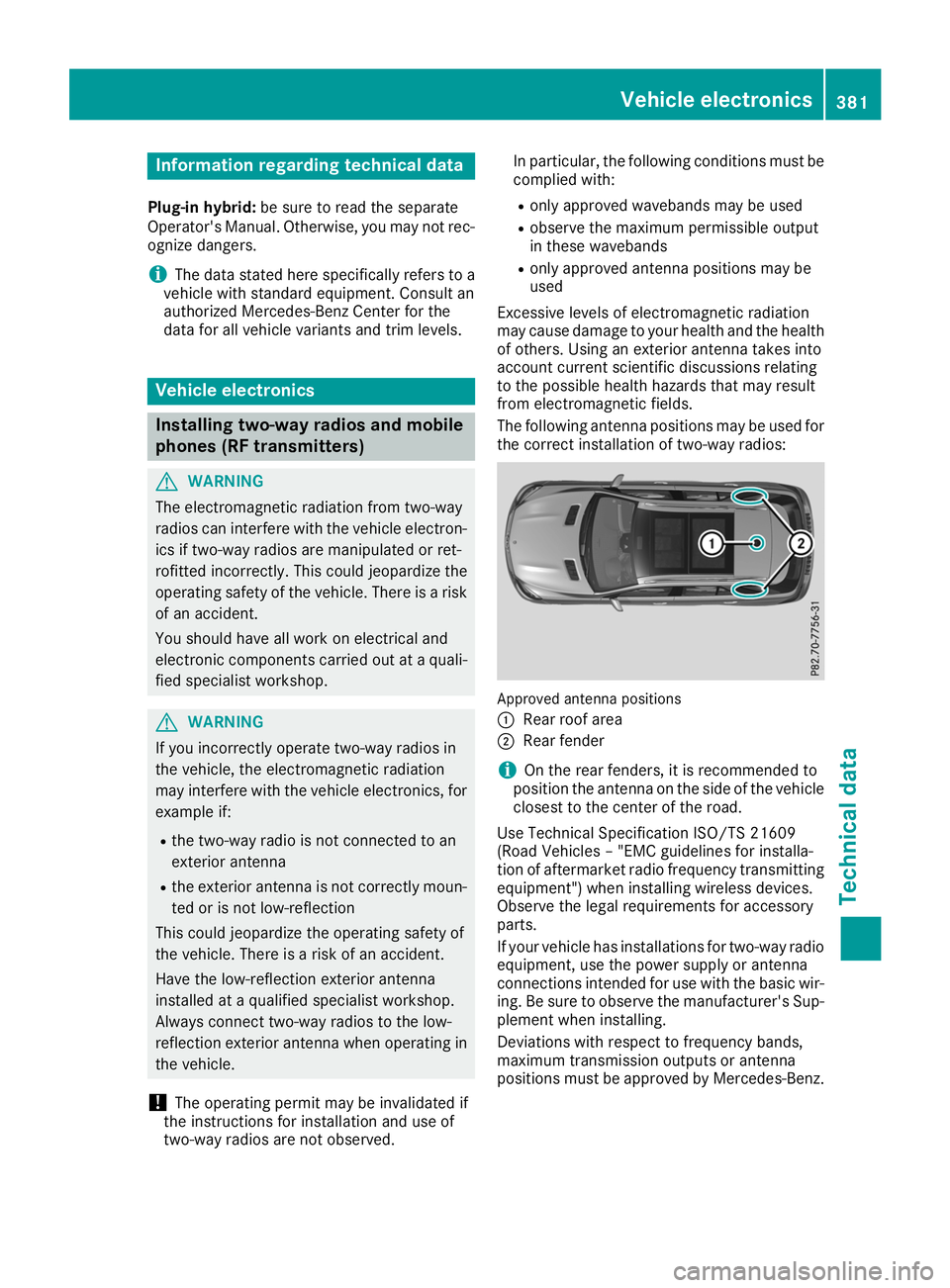
The following antenna positions may be used for
the correct installation of two-way radios: Approved antenna positions
0043
Rear roof area
0044 Rear fender
i On the rear fenders, it is recommended to
position the antenna on the side of the vehicle
closest to the center of the road.
Use Technical Specification ISO/TS 21609
(Road Vehicles – "EMC guidelines for installa-
tion of aftermarket radio frequency transmitting
equipment") when installing wireless devices.
Observe the legal requirements for accessory
parts.
If your vehicle has installations for two-way radio
equipment, use the power supply or antenna
connections intended for use with the basic wir-
ing. Be sure to observe the manufacturer's Sup- plement when installing.
Deviations with respect to frequency bands,
maximum transmission outputs or antenna
positions must be approved by Mercedes-Benz. Vehicle electronics
381Technical data Z
Page 393 of 398

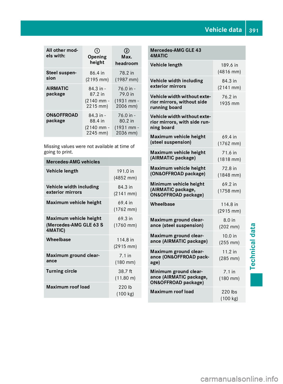
All other mod-
els with:
0043 0043
Opening height 0044
0044
Max.
headroom Steel suspen-
sion
86.4 in
(2195 mm) 78.2 in
(1987 mm) AIRMATIC
package
84.3 in -
87.2 in
(2140 mm - 2215 mm) 76.0 in -
79.0 in
(1931 mm - 2006 mm) ON&O
FFROAD
package 84.3 in -
88.4 in
(2140 mm - 2245 mm) 76.0 in -
80.2 in
(1931 mm - 2036 mm) Missing values
were not available at time of
going to print. Mercedes
‑AMG vehicles Vehicle length
191.0 in
(4852 mm) Vehicle width including
exterior mirrors
84.3 in
(2141 mm) Maximum vehicle height
69.4 in
(1762 mm) Maximum vehicle height
(Mercedes-AMG GLE 63 S
4MATIC)
69.3 in
(1760 mm) Wheelbase
114.8 in
(2915 mm) Maximum ground clear-
ance
7.1 in
(180 mm) Turning circle
38.7 ft
(11.80 m) Maximum roof load
220 lb
(100 kg) Mercedes-AMG GLE 43
4MATIC
Vehicle length
189.6 in
(4816 mm) Vehicle width including
exterior mirrors
84.3 in
(2141 mm) Vehicle width without exte-
rior mirrors, without side
running board 76.2 in
1935 mm Vehicle width without exte-
rior mirrors, with side run-
ning board Maximum vehicle height
(steel suspension)
69.4 in
(1762 mm) Maximum vehicle height
(AIRMATIC package)
71.6 in
(1818 mm) Maximum vehicle height
(ON&OFFROAD package)
72.8 in
(1848 mm) Minimum vehicle height
(AIRMATIC package,
ON&OFFROAD package)
69.2 in
(1758 mm) Wheelbase
114.8 in
(2915 mm) Maximum ground clear-
ance (steel suspension)
8.0 in
(202 mm) Maximum ground clear-
ance (AIRMATIC package)
10.0 in
(255 mm) Maximum ground clear-
ance (ON&OFFROAD pack-
age)
11.2 in
(285 mm) Minimum ground clear-
ance (AIRMATIC package,
ON&OFFROAD package)
7.1 in
(180 mm) Maximum roof load
220 lbs
(100 kg) Vehicle data
391Technical data Z
Page 394 of 398

All other models
Vehicle width including
exterior mirrors 84.3 in
(2141 mm) Maximum vehicle height
(steel suspension)
70.7 in
(1796 mm) Maximum vehicle height
(AIRMATIC package)
71.6 in
(1818 mm) Maximum vehicle height
(ON&OFFROAD package)
72.8 in
(1848 mm) Minimum vehicle height
69.2 in
(1758 mm) Wheelbase
114.8 in
(2915 mm) Maximum ground clear-
ance (steel suspension)
8.0 in
(202 mm) Maximum ground clear-
ance (AIRMATIC package)
10.0 in
(255 mm) Maximum ground clear-
ance (ON&OFFROAD pack-
age)
11.2 in
(285 mm) Minimum ground clear-
ance
7.1 in
(180 mm) Turning circle
38.7 ft
(11.80 m) Maximum roof load
220 lb
(100 kg) Model Vehicle
length GLE 400 4MATIC
GLE 550 4MATIC
189.5 in
(4813 mm) All other models
189.7 in
(4819 mm) Vehicle data for off-road driving
Fording depth
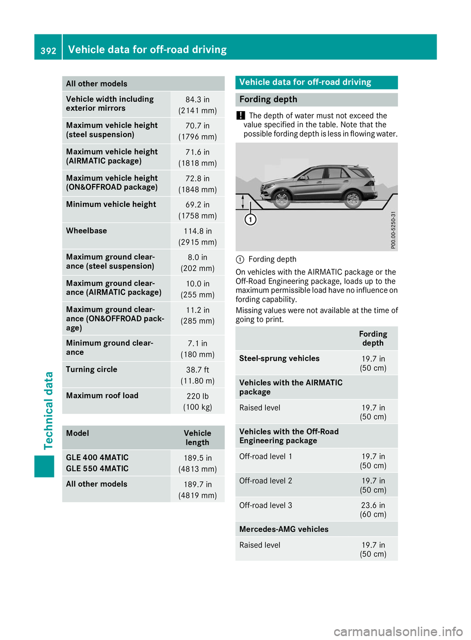
! The depth of water must not exceed the
value specified in the table. Note that the
possible fording depth is less in flowing water. 0043
Fording depth
On vehicles with the AIRMATIC package or the
Off-Road Engineering package, loads up to the
maximum permissible load have no influence on fording capability.
Missing values were not available at the time of
going to print. Fording
depth Steel-sprung vehicles
19.7 in
(50 cm) Vehicles with the AIRMATIC
package Raised level 19.7 in
(50 cm) Vehicles with the Off-Road
Engineering package
Off-road level 1 19.7 in
(50 cm) Off-road level 2 19.7 in
(50 cm) Off-road level 3 23.6 in
(60 cm) Mercedes-AMG vehicles
Raised level 19.7 in
(50 cm) 392
Vehicle data for off-road drivingTechnical data